2014 SUBARU TRIBECA battery
[x] Cancel search: batteryPage 116 of 426
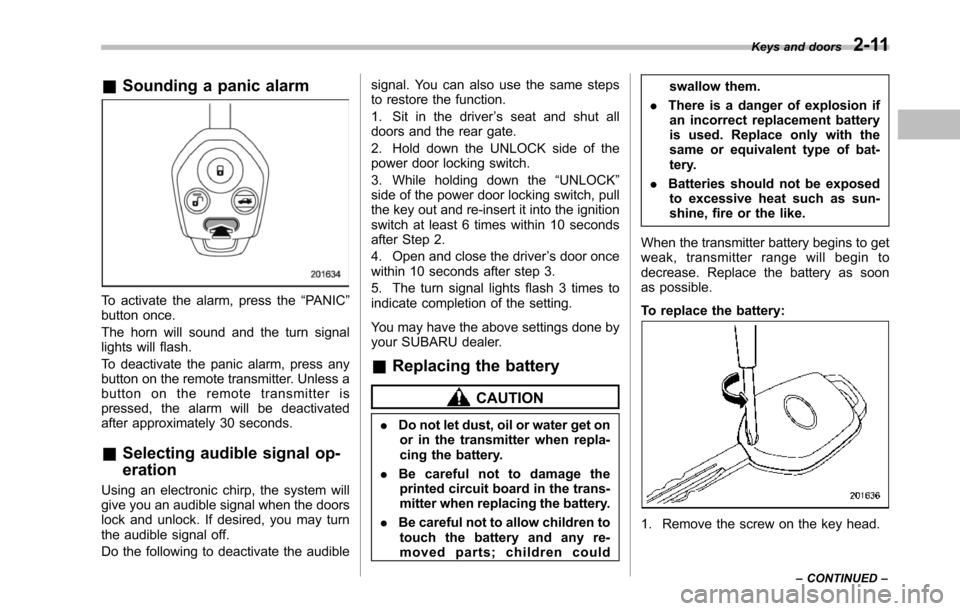
&Sounding a panic alarm
To activate the alarm, press the“PANIC”button once.
The horn will sound and the turn signallights will flash.
To deactivate the panic alarm, press anybuttonon the remote transmitter. Unless abutton on the remote transmitter ispressed, the alarm will be deactivatedafter approximately 30 seconds.
&Selecting audible signal op-
eration
Using an electronic chirp, the system willgive you an audible signal when the doorslock and unlock. If desired, you may turnthe audible signal off.
Do the following to deactivate the audible
signal. You can also use the same stepsto restore the function.
1. Sit in the driver’s seat and shut alldoors and the rear gate.
2. Hold down the UNLOCK side of thepower door locking switch.
3. While holding down the“UNLOCK”sideof the power door locking switch, pullthe key out and re-insert it into the ignitionswitch at least 6 times within 10 secondsafter Step 2.
4. Open and close the driver’s door oncewithin 10 seconds after step 3.
5. The turn signal lights flash 3 times toindicate completion of the setting.
You may have the above settings done byyour SUBARU dealer.
&Replacing the battery
CAUTION
.Do not let dust, oil or water get onor in the transmitter when repla-cing the battery.
.Be careful not to damage theprinted circuit board in the trans-mitter when replacing the battery.
.Be careful not to allow children totouch the battery and any re-moved parts; children could
swallow them.
.There is a danger of explosion ifan incorrect replacement batteryis used. Replace only with thesame or equivalent type of bat-tery.
.Batteries should not be exposedto excessive heat such as sun-shine, fire or the like.
When the transmitter battery begins to getweak, transmitter range will begin todecrease. Replace the battery as soonas possible.
To replace the battery:
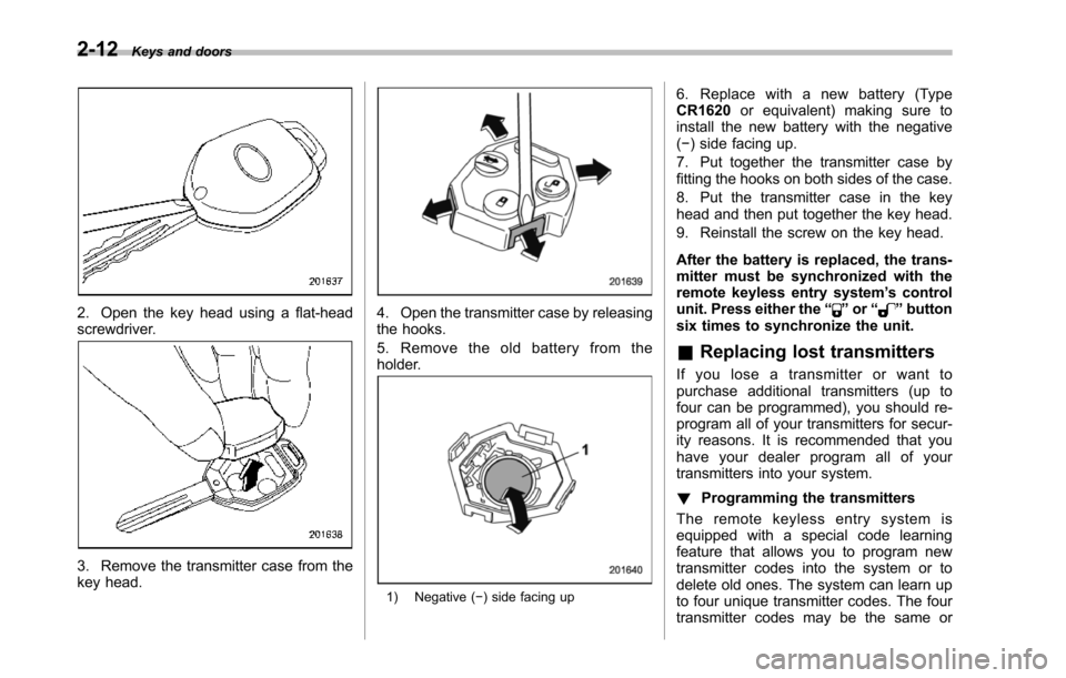
1. Remove the screw on the key head.
Keys and doors2-11
–CONTINUED–
Page 117 of 426
2-12Keys and doors
2. Open the key head using a flat-headscrewdriver.
3. Remove the transmitter case from thekey head.
4. Open the transmitter case by releasingthe hooks.
5. Remove the old battery from theholder.
1) Negative (!) side facing up
6. Replace with a new battery (TypeCR1620or equivalent) making sure toinstall the new battery with the negative(!) side facing up.
7. Put together the transmitter case byfitting thehooks on both sides of the case.
8. Put the transmitter case in the keyhead and then put together the key head.
9. Reinstall the screw on the key head.
After the battery is replaced, the trans-mitter must be synchronized with theremote keyless entry system’s controlunit. Press either the“”or“”buttonsix times to synchronize the unit.
&Replacing lost transmitters
If you lose a transmitter or want topurchase additional transmitters (up tofour can be programmed), you should re-program all of your transmitters for secur-ity reasons. It is recommended that youhave your dealer program all of yourtransmittersinto your system.
!Programming the transmitters
The remote keyless entry system isequipped witha special code learningfeature that allows you to program newtransmitter codes into the system or todelete old ones. The system can learn upto four unique transmitter codes. The fourtransmitter codes may be the same or
Page 123 of 426
2-18Keys and doors
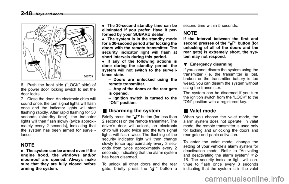
6. Push the front side (“LOCK”side) ofthe power door locking switch to set thedoor locks.
7. Close the door. An electronic chirp willsound once,the turn signal lights will flashonce and the indicator lights will startflashing rapidly. After rapid flashing for 30seconds (standby time), the indicatorlights will then flash slowly (twice approxi-mately every 2 seconds), indicating thatthe system has been armed for surveil-lance.
NOTE
.The system can be armed even if theengine hood, the windows and/ormoonroof are opened. Always makesure that they are fully closed beforearming the system.
.The 30-second standby time can beeliminated if you prefer. Have it per-formed by your SUBARU dealer..The system is in the standby modefor a 30-second period after locking thedoors with the remote transmitter. Thesecurity indicator light will flash atshort intervals during this period..If any of the following actions isdoneduring the standby period, thesystem will not switch to the surveil-lance state.–Doors are unlocked using theremote transmitter.–Any of the doors or the rear gateis opened.–Ignition switch is turned to the“ON”position.
&Disarming the system
Briefly press the“”button (for less than2 seconds) on the remote transmitter. Thedriver’s door will unlock, an electronicchirp will sound twice and the turn signallights willflash twice. The flashing of thesecurity indicator light will then changeslowly (once approximately every 3 sec-onds from twice approximately every 2seconds), indicating that the alarm systemhas been disarmed.
To unlock all other doors and the reargate, briefly press the“”button a
second time within 5 seconds.
NOTE
If the interval between the first andsecond presses of the“”button (forunlocking of all of the doors and therear gate) is extremely short, the sys-tem may not respond.
!Emergency disarming
If you cannot disarm the system using thetransmitter (i.e. the transmitter is lost,broken or the transmitter battery is tooweak), you can disarm the system withoutusing the transmitter.
The system can be disarmed if you turnthe ignition switch from the“LOCK”to the“ON”position with a registered key.
&Valet mode
When you choose the valet mode, thealarm system does not operate. In valetmode, the remote transmitter is used onlyfor locking and unlocking the doors andrear gate and panic activation.
To enter the valet mode, change thesetting of your vehicle’s alarm system fordeactivation mode. Refer to“Activatingand deactivatingthe alarm system”F2-16. The security indicator light will con-tinue to flash once every 3 secondsindicating that the system is in the valet
Page 130 of 426
NOTE
If the rear gate cannot be unlocked dueto a discharged vehicle battery, amalfunction in the door locking/unlock-ing system or other causes, you canunlock it by manually operating therear gate lock release lever. For theprocedure, refer to“Rear gate–if therear gate cannot be unlocked”F9-18.
Moonroof (if equipped)
WARNING
Never let anyone’shands,arms,head or any objects protrude fromthe moonroof. A person could beseriously injured if the vehicle stopssuddenly or turns sharply or if thevehicle is involved in an accident.
To a v o i d s e r i o u s p e r s o n a l i n j u r ycaused by entrapment, always con-form to the following instructionswithoutexception.
.Before closing the moonroof,make sure that no one’s hands,arms, head or other objects willbe accidentally caught in themoonroof.
.Before leaving the vehicle, al-ways remove the key from theignition switch for safety andnever allow an unattended childto remain in the vehicle. Failureto follow this procedure couldresult in injury to a child operat-ingthe moonroof.
.Never try to check the anti-en-trapment function by deliberatelyplacing part of your body in themoonroof.
CAUTION
.Do not sit on the edge of the openmoonroof.
.Do not operate the moonroof iffalling snow or extremely coldconditions have caused it tofreeze shut.
.The anti-entrapment functiondoes not operate when the moon-roof is being tilted down. Be sureto confirm that it is safe to do sobeforetilting the moonroof down.
The moonroofhas both tilting and slidingfunctions.
The moonroof operates only when theignition switch is in the“ON”position.
Keys and doors2-25
–CONTINUED–
Page 136 of 426
Ignition switch
WARNING
.Never turn the ignition switch to“LOCK”while the vehicle isbeing driven or towed becausethat will lock the steering wheel,preventing steering control. Andwhen the engine is turned off, ittakes a much greater effort thanusual to steer.
.Before leaving the vehicle, al-ways removethe key from theignition switch for safety andnever allow an unattended childto remain in the vehicle. Failureto follow this procedure couldresult in injury to a child orothers. Children could operatethe power windows, the moon-roof or other controls or evenmake the vehicle move.
CAUTION
Do not attach a large key holder orkey case to either key. If it bangedagainst your knees or hands whileyou were driving, it could turn theignition switch from the“ON”posi-
tion to the“Acc”or“LOCK”posi-tion, thereby stopping the engine.Also, if the key is attached to akeyholder or to a large bunch ofother keys, centrifugal force may acton it as the vehicle moves, resultingin unwanted turning of the ignitionswitch.
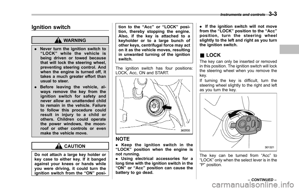
The ignition switch has four positions:LOCK, Acc, ON and START.
NOTE
.Keep the ignition switch in the“LOCK”position when the engine isnot running..Using electrical accessories for along time with the ignition switch in the“ON”or“Acc”position can cause thebattery to go dead.
.If the ignition switch will not movefrom the“LOCK”position to the“Acc”position, turn the steering wheelslightly to the left and right as you turnthe ignition switch.
&LOCK
The key can only be inserted or removedin this position. The ignition switch will lockthe steering wheel when you remove thekey.
If turning the key is difficult, turn thesteering wheel slightly to the right and leftas you turn the key.
The key can be turned from“Acc”to“LOCK”only when the select lever is in the“P”position.
Instruments and controls3-3
–CONTINUED–
Page 140 of 426
The odometer/trip meter will also turn off ifyou open and close the driver’sdoorwithin 10 seconds of illumination of theodometer/trip meter.
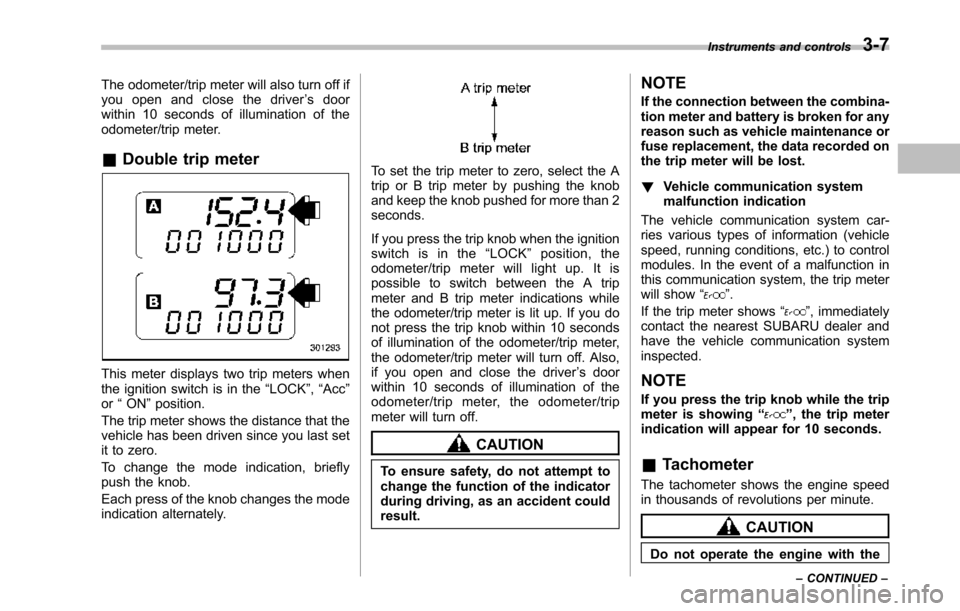
&Double trip meter
This meter displays two trip meters whenthe ignition switch is in the“LOCK”,“Acc”or“ON”position.
The trip metershows the distance that thevehicle has been driven since you last setit to zero.
To change the mode indication, brieflypush the knob.
Each press of the knob changes the modeindication alternately.
To set the trip meter to zero, select the Atrip or B trip meter by pushing the knoband keep the knob pushed for more than 2seconds.
If you press the trip knob when the ignitionswitch is in the“LOCK”position, theodometer/trip meter will light up. It ispossible to switch between the A tripmeter and B trip meter indications whilethe odometer/trip meter is lit up. If you donot press the trip knob within 10 secondsof illumination of the odometer/trip meter,the odometer/trip meter will turn off. Also,if you open and close the driver’s doorwithin 10 seconds of illumination of theodometer/trip meter, the odometer/tripmeter will turn off.
CAUTION
To ensure safety, do not attempt tochange thefunction of the indicatorduring driving, as an accident couldresult.
NOTE
If the connection between the combina-tion meter and battery is broken for anyreason such as vehicle maintenance orfuse replacement, the data recorded onthe trip meter will be lost.
!Vehicle communication systemmalfunction indication
The vehicle communication system car-ries various types of information (vehiclespeed, running conditions, etc.) to controlmodules. In the event of a malfunction inthis communication system, the trip meterwill show“”.
If the trip meter shows“”, immediatelycontact the nearest SUBARU dealer andhavethe vehicle communication systeminspected.
NOTE
If you press the trip knob while the tripmeter is showing“”, the trip meterindication will appear for 10 seconds.
&Tachometer
The tachometer shows the engine speedin thousands of revolutions per minute.
CAUTION
Do not operate the engine with the
Instruments and controls3-7
–CONTINUED–
Page 149 of 426
3-16Instruments and controls
gether with the brake system warning lightif the EBD system becomes malfunction-ing. For further details of the EBD systemmalfunction warning, refer to“Brake sys-tem warning light”F3-16.
NOTE
If the warning light behavior is asdescribed in the following, the ABSsystem may be considered normal.
.The warning light illuminates rightafter the engine is started but turns offimmediately, remaining off..The warning light remains illumi-nated after the engine has been started,but it turns off when the vehicle speedreaches approximately 8 mph (12km/h)..The warning light illuminates duringdriving, but it turns off immediately andremains off.
When driving with an insufficient batteryvoltage such as when the engine is jumpstarted, the ABS warning light may illumi-nate. This is due to the low battery voltageand does not indicate a malfunction.When the battery becomes fully charged,the light will turn off.
&Brake system
warning light
WARNING
.Driving with the brake systemwarning light illuminated is dan-gerous. This indicates your brakesystem may not be workingproperly. If the light remainsilluminated, have the brakes in-spected by a SUBARU dealerimmediately.
.If at all in doubt about whetherthe brakes are operating prop-erly, do not drive the vehicle.Have your vehicle towed to thenearest SUBARU dealer for re-pair.
This light has the following three functions.
!Parking brake warning
The light illuminates with the parkingbrakeapplied while the ignition switch isin the“ON”position. It turns off when theparking brake is fully released.
!Brake fluid level warning
This light illuminateswhen the brake fluidlevel has dropped to near the“MIN”levelof the brake fluid reservoir with the ignitionswitch in the“ON”position and with the
parking brake fully released.
If the brake system warning light shouldilluminate while driving (with the parkingbrake fully released and with the ignitionswitch positioned in“ON”), it could be anindication of leaking of brake fluid or wornbrake pads. If this occurs, immediatelystop the vehicle at the nearest safe placeand check the brake fluid level. If the fluidlevel is below the“MIN”mark in thereservoir, do not drive the vehicle. Havethe vehicle towed to the nearest SUBARUdealer for repair.
!Electronic Brake Force Distribution(EBD) system warning
The brake system warning light alsoilluminates if a malfunction occurs in theEBD system. In that event, it illuminatestogether with the ABS warning light.
The EBD system may be malfunctioning ifthe brakesystem warning light and ABSwarning light illuminate simultaneouslyduring driving.
Even if the EBD system fails, the conven-tional braking system will still function.However, the rear wheels will be moreprone to locking when the brakes areapplied harder than usual and the vehi-cle’s motion may therefore become some-what harder to control.
If the brake system warning light and ABS
Page 160 of 426
&Journey time
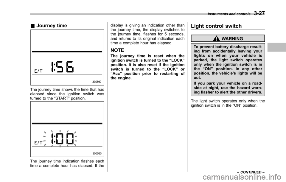
The journey time shows the time that haselapsed since the ignition switch wasturned to the“START”position.
The journey time indication flashes eachtime a complete hour has elapsed. If the
display is giving an indication other thanthe journey time, the display switches tothe journey time, flashes for 5 seconds,and returns to its original indication eachtime a complete hour has elapsed.
NOTE
The journey time is reset when theignition switch is turned to the“LOCK”position. It is also reset if the ignitionswitch is turned to the“LOCK”or“Acc”position prior to restarting ofthe engine.
Light control switch
WARNING
To prevent battery discharge result-ing from accidentally leaving yourlights on when your vehicle isparked, the light switch operatesonly when the ignition switch is inthe“ON”position. In any otherposition, the vehicle’s lights will beout.
If you park your vehicle on a road-side at night, use the hazard warn-ing flasher to alert the other drivers.
The light switch operates only when theignition switch is in the“ON”position.
Instruments and controls3-27
–CONTINUED–