Page 105 of 248
 must be")
Class N1 vehiclesRead and observe
and on page 96 first.
On class N1 vehicles, which are not fitted with a protective grille, a lashing set
which complies with the standard EN 12195 (1 - 4) must be used for fastening
the load.
Proper functioning of the electrical installation is essential for safe vehicle op-
eration. It is important to ensure that the electrical installation is not damaged
during the adjustment process or when the storage area is being loaded and
unloaded.
Variable loading floor in the luggage compartment (Estate)
Introduction
This chapter contains information on the following subjects:
Removing and inserting the variable loading floor
102
Securing the loading floor in the raised position
102
Removing and refitting carrier rails
103
Using the variable loading floor with a spare wheel
103
The variable loading floor makes it easier to handle bulky goods and creates an
even boot floor when the rear seat backrests are folded forward.
CAUTION
The maximum permissible load of the variable loading floor is 75 kg.
Note
The room under the variable loading floor can be used to stow objects.Removing and inserting the variable loading floorFig. 105
Fold up / removal variable loading floor
Read and observe
on page 102 first.
›
Fold the variable loading floor together using the handle
A
and fold in the
direction of
1
» Fig. 105 .
›
Fold up the variable loading floor in direction of arrow
2
.
›
Pull on both sides of the locking levers in direction of arrow
3
.
›
Remove the variable loading floor in direction of arrow
4
.
Insertion takes place in reverse order.
Securing the loading floor in the raised position
Fig. 106
Secured loading floor in the
raised position
Read and observe on page 102 first.
›
Fold up the hooks on the fastening strip in direction of arrow
1
» Fig. 98 on
page 98 .
›
Fold up the variable loading floor behind the rear back backrests.
102Using the system
Page 106 of 248

›Fold down the hooks in direction of arrow 3
» Fig. 98 on page 98 as far as
the stop.›
Support the variable loading floor on the hooks folded downwards » Fig. 106.
Removing and refitting carrier rails
Fig. 107
Slacken check points/remove carrier rails
Read and observe
on page 102 first.
Removing
›
Undo the securing points
B
» Fig. 107 on the carrier rails using the vehicle
key or a flat screwdriver.
›
Hold the carrier rail
A
in the front area and remove by pulling in the direction
of arrow
1
.
›
Hold the carrier rail
A
in the rear area and loosen and remove by pulling in
the direction of arrow
2
.
Fitting
›
Position the carrier rails on the sides of the boot.
›
Press the two securing points
B
» Fig. 107 on each carrier rail to the stop.
›
Check the attachment of the carrier rails by pulling it.
WARNINGPay attention when installing the variable loading floor that the carrier rails
and the variable loading floor are correctly fixed, otherwise the occupants
are at risk.Using the variable loading floor with a spare wheelFig. 108
Fold up the side panels of the variable loading floor / space un-
der the variable loading floor
Read and observe
on page 102 first.
The sides of the variable loading floor can be folded in the direction of ar-
row » Fig. 108 -
.
The room under the variable loading floor » Fig. 108 -
can be used to stow
objects.
Roof rack
Introduction
This chapter contains information on the following subjects:
Roof load
104WARNING■ The transported items on the roof rack must be securely attached – risk
of accident!■
Always secure the load with appropriate and undamaged lashing straps
or tensioning straps.
■
Distribute the load evenly over the roof rack system.
■
When transporting heavy objects or objects which take up a large area on
the roof rack system, the handling of the car may change as a result of the
displacement of the centre of gravity. The style of driving and speed must
therefore be adapted to the current circumstances.
103Transporting and practical equipment
Page 107 of 248
■Avoid abrupt and sudden driving/braking manoeuvres.■The permissible roof load, permissible axle loads and permissible total ve-
hicle weight must not be exceeded under any circ")
WARNING (Continued)■Avoid abrupt and sudden driving/braking manoeuvres.■The permissible roof load, permissible axle loads and permissible total ve-
hicle weight must not be exceeded under any circumstances – risk of acci-
dent!
CAUTION
■ Only roof racks from the ŠKODA Original Accessories range should be used.■When dealing with roof rack systems, the installation instructions supplied
with the roof luggage rack system must be observed.■
On vehicles with a panoramic sunroof, make sure that the tilted panorama
roof does not strike any items which are transported.
■
Ensure that the boot lid does not hit the roof load when opened.
For the sake of the environment
The increased aerodynamic drag results in a higher fuel consumption.
Roof load
Read and observe
and on page 103 first.
The maximum permissible roof load (including roof rack system) of 100 kg and
the maximum permissible total weight of the vehicle should not be exceeded.
The full permissible roof load cannot be used if a roof rack system with a lower
load carrying capacity is used. In this case, the roof rack system must only be
loaded up to the maximum weight limit specified in the fitting instructions.
Heating and air conditioning
Heating, ventilation, cooling
Introduction
This chapter contains information on the following subjects:
Air outlet vents
105
Air distribution control
106
Heating
107
Air conditioning (manual air conditioning)
107
Climatronic (automatic air conditioning)
108
Efficient handling of the cooling system
109
malfunctions
109
The heating and air conditioning ventilate and heat the vehicle interior. The air
conditioning system also cools and dehumidifies the vehicle interior.
The heating effect is dependent upon the coolant temperature, thus full heat
output only occurs when the engine has reached its operating temperature.
The cooling system only operates if the following conditions are met: The cooling system is switched on.
The engine is running.
The outside temperature is above approx. +2 °C.
The blower is switched on.
If the cooling system is switched on, the temperature and air humidity drops in
the vehicle. The cooling system prevents the windows from misting up during
the cold season of the year.
It is possible to briefly activate recirculated air mode to enhance the cooling
effect » page 106 .
WARNING■
For your own safety and that of other road users, ensure that all the win-
dows are free of ice, snow and misting.■
The blower should always be on to prevent the windows from misting up.
104Using the system
Page 108 of 248
■Under certain circumstances, air at a temperature of about 5 °C can flow
out of the vents when the cooling system is switched on.■
To reduce health risks (e.g. common colds),")
WARNING (Continued)■Under certain circumstances, air at a temperature of about 5 °C can flow
out of the vents when the cooling system is switched on.■
To reduce health risks (e.g. common colds), the following instructions for
the use of the cooling system are to be observed. ■The difference between the indoor temperature and the outdoor air
temperature should not be greater than about 5 ° C.
■ The cooling system is to be turned off about 10 minutes before the end
of the journey.
■ Once a year, a disinfection of the air conditioner or the Climatronic is to
be carried out by a specialist company.
CAUTION
■ The air inlet in front of the windscreen must be free of e.g. ice, snow or
leaves to ensure that the heating and cooling system operates properly.■
After switching on the cooling Condensation from the evaporator of the air
conditioning may drip down and form a puddle below the vehicle. This is not a
leak!
■
If the coolant temperature is too high, the cooling system is switched off to
ensure that the engine cools down.
Note
The used air streams out through the vents in the luggage compartment.
Air outlet vents
Fig. 109
Air vents at the front
Fig. 110
Air vents at the rear
Read and observe
and on page 104 first.
Warmed, not warmed fresh or cooled air will flow out of the opened air outlet vents according to the setting of the control dial and the outside atmospheric
conditions.
The direction of airflow can be adjusted using the air outlet vents 3,
4 » Fig. 109 and 6 » Fig. 110 - the outlets can be opened and closed individually.
Open the air outlet vents 3 and 4
›
Turn the knob
B
to the position
» Fig. 109 .
Close air outlet vents 3 and 4
›
Turn the knob
B
to the 0 » Fig. 109 .
Open the air outlet vents 6
›
Turn the knob
C
between the end positions » Fig. 110.
Close air outlet vents 6
›
Turn the knob
C
to the end position » Fig. 110.
Change air flow of air outlet vents 3 and 4
›
To change the height of the air flow, swivel the horizontal fins with the mov-
able adjuster
A
upward or downward » Fig. 109.
›
To adjust the lateral direction of the air flow, turn the vertical fins with the
movable adjuster
A
to the left or to the right.
Change air flow of air outlet vents 6
›
To change the height of the air flow, swivel the horizontal fins with the mov-
able adjuster
A
upward or downward » Fig. 110.
›
To adjust the lateral direction of the air flow, turn the vertical fins with the
movable adjuster
A
to the left or to the right.
105Heating and air conditioning
Page 109 of 248

An overview of the available settings for adjusting the direction of the air
outletSet the direction of the air outletActive air outlet nozzles » Fig. 109
and » Fig. 110 1, 2 , 41, 2 , 4 , 5 , 7 3, 4 , 64 , 5 , 7
Note
■
To ensure that the heating and air conditioning systems work properly, do
not block the air outlet vents.■
The air outlet vents 6 » Fig. 110 are only fitted on vehicles with the higher
centre console.
Air distribution control
Read and observe
and on page 104 first.
Recirculated air mode prevents polluted air outside the vehicle from getting in-to the vehicle, e.g. when driving through a tunnel or in a traffic jam.
In recirculated air mode air is sucked out of the interior of the vehicle and then
fed back into the interior.
Heating and air conditioning (manual air conditioning)
To turn the recirculation mode on or off, press the Symbol key
.
The air recirculation mode is automatically turned off by turning the air distri-
bution control
C
to position
» Fig. 111 on page 107 or » Fig. 112 on
page 107 .
Recirculated air mode can be switched on again from this position by repeat-
edly pressing the symbol button .
Climatronic (automatic air conditioning)
To turn the recirculation mode on, press the Symbol key
repeatedly until
the indicator light is lit on the left side of the button.
To activate the automatic recirculation mode, press the Symbol key re-
peatedly until the indicator light is lit on the right side of the button.
Climatronic has an air quality sensor for the detection of the pollutant concen-
tration in the sucked-in air.
If a considerable increase in concentration of pollutants is recognised by the
air quality sensor, recirculated air mode will temporarily be switched on.
If the concentration of pollutants decreases to the normal level, the air distri-
bution control is automatically switched off so that fresh air can be guided into
the vehicle interior.
If the air quality sensor does not automatically switch on the recirculated air
mode in the event of an unpleasant odour, you can switch it on yourself by
pressing the button . The indicator light lights up in the button on the left
side.
To turn off the air recirculation or to deactivate the automatic air recircula-
tions , press the
button of press the
symbol button repeatedly until
the warning lights in the button go out.WARNINGThe recirculation system cannot be switched on for a longer period of time,
because there is no supply of fresh air from the outside. “Stale air” may re-
sult in fatigue in the driver and occupants, reduce attention levels and also
cause the windows to mist up. The risk of having an accident increases.
Switch off recirculated air mode as soon as the windows start to mist up.
CAUTION
We recommend not smoking in the vehicle when the recirculating air operation
is switched on. The smoke sucked from inside the vehicle is deposited on the
evaporator of the air conditioner. This produces a permanent odour when the
air conditioning system is operating which can only be eliminated through con-
siderable effort and expense (replacement of compressor).
Note
The automatic air distribution control operates only if the outside temperature
is higher than approx. 2 °C.106Using the system
Page 110 of 248

HeatingFig. 111
Heating Controls
Read and observe
and on page 104 first.
Individual functions can be switched on or off by turning the knob or pressing the respective button. If the function is switched on, the warning light lights
up.
Functions of the individual controls » Fig. 111
Setting temperature ›
Lower temperature
›
Increase temperature
Set the blower level (level 0: blower, level 4: the highest blower speed)
Set the direction of the air outlet » page 105
›
Air flow to the windows
›
Air flow to the upper body
›
Air flow in the footwell
›
Airflow to the windows and into the footwell
Switching the rear window heater on/off » page 71
Switching on / off aux. heater (parking heater) on / off » page 111
Switch recirculation on/off » page 106
ABCAir conditioning (manual air conditioning)Fig. 112
Controls of the air conditioning
Read and observe
and on page 104 first.
Individual functions can be switched on or off by turning the knob or pressing the respective button. If the function in the button illuminates the warning
light.
Functions of the individual controls » Fig. 112
Setting temperature ›
Lower temperature
›
Increase temperature
Set the blower level (level 0: Blowers, level 4: the highest blower speed)
Set the direction of the air outlet » page 105
›
Air flow to the windows
›
Air flow to the upper body
›
Air flow in the footwell
›
Airflow to the windows and into the footwell
Switching the cooling system on/off
Switching the rear window heater on/off » page 71
Switching on/off aux. heater (parking heater) on/off » page 111
Switch recirculation on/off » page 106
Operation of the seat heater on the front left seat » page 80
Operation of the seat heater on the front right seat » page 80
ABC107Heating and air conditioning
Page 111 of 248

Note■The warning light in the button lights after activation, even if not all of
the conditions for the function of the cooling system have been met. By light-
ing up of the indicator light in the button, the operational readiness of the
cooling system is signalled.■
During operation of the air conditioning, an increase in engine idle speed may
occur under certain circumstances in order to ensure sufficient heating com-
fort.
Climatronic (automatic air conditioning)
Fig. 113
Controls the Climatronic
Read and observe
and on page 104 first.
The Climatronic in automatic mode ensures the best-possible setting of the
temperature of the outflowing air, the blower stage and air distribution.
The system also takes sunlight into account, which eliminates the need to al-
ter the settings manually.
Individual functions can be switched on or off by turning the knob or pressing
the respective button. If the function in the button illuminates the warning
light.
Functions of the individual controls » Fig. 113
Adjust the temperature for the left side or for both sides
›
Lower temperature
›
Increase temperature
Interior temperature sensor
ABDepending on equipment fitted:
›
Switching the windscreen heater on/off » page 71
›
Switching on/off aux. heating (standard heating) on/off » page 111
Adjust the temperature for the right side ›
Lower temperature
›
Increase temperature
Operation of the seat heater on the front left seat » page 80
Operation of the seat heater on the front right seat » page 80
Adjust the blower speed › + Increase speed
› - Reduce speed
Switch the intensive windscreen heater on/off
Air flow to the windows
Air flow to the upper body
Air flow in the footwell Automatic recirculation, switch on or off » page 106
Switching the rear window heater on/off » page 71
Switching automatic mode on
Switching Climatronic system off »
Switching the cooling system on/off
Switch the temperature setting in Dual mode on/off
After the cooling system is switched off, only the ventilation function remains active whereby the minimum temperature that can be reached is the outside
temperature.
Setting temperature
The interior temperature for the left and right side can be set separately or to-
gether.
The temperature for both sides, is set by turning the knob
A
» Fig. 113 (the
indicator light in the button is not illuminated).
The temperature for the right side is adjusted by turning the knob
D
(the in-
dicator light in the button is lit).
The temperature for the left side is adjusted by turning the knob
A
(the indi-
cator light in the button is lit).
The interior temperature can be set between +18 °C and +26 ℃. The interior
temperature is regulated automatically within this range.
CD108Using the system
Page 112 of 248

If a temperature lower than +18 °C is selected, a blue symbol lights up at the
start of the numerical scale.
If a temperature higher than +26 °C is selected, the
symbol lights up at the
start of the numerical scale.
At both end positions, Climatronic runs at maximum cooling/heating output
and the temperature is automatically not regulated.
Controlling blower
The Climatronic system controls the blower stages automatically in line with the interior temperature. However, the blower stages can be manually adap-
ted to suit your particular needs.
If the blower speed is reduced to a minimum, Climatronic is switched off.
The set blower speed is displayed above the symbol button when the re-
spective number of indicator lights come on.
Automatic mode
The automatic mode is used in order to maintain a constant temperature and to demist the windows in the interior of the car.
If the warning light in the top right corner of the button lights up, the Cli-
matronic operates in “HIGH”-mode. The “HIGH” mode is the standard setting of
the Climatronic.
Upon pressing the button again, the Climatronic switches to “LOW”-mode
and the indicator light in the top left corner lights up. The Climatronic uses on-
ly in this mode the lower blower speed. However taking into account the noise
level, this is more comfortable, yet be aware that the effectiveness of the air
conditioning system is reduced particularly if the vehicle is fully occupied.
By pressing the button again, it is changed to “HIGH”-mode.
Automatic mode is switched off by pressing one of the buttons for the air dis- tribution or by increasing/decreasing the blower speed. The temperature is
nevertheless regulated.WARNING■ Do not switch off the Climatronic system for longer than necessary.■Switch on the Climatronic system as soon as the windows mist up.Note■ Do not stick anything onto or cover the interior temperature sensorB » Fig. 113 as this could impair the functioning of the Climatronic.■
If the windscreen mists up, press the symbol button
. Press the button
once the windscreen has demisted.
■
During operation of the Climatronic, an increase in engine idle speed can oc-
cur under certain circumstances in order to ensure adequate heating comfort.
■
For vehicles with factory-fitted radio the Climatronic information also ap-
pears on its display. This function can be switched off, see » Radio manual .
Efficient handling of the cooling system
Read and observe
and on page 104 first.
The air conditioning system compressor uses power from the engine when incooling mode, which will affect the fuel consumption.
It recommended to open the windows or the doors of a vehicle for which the
interior has been strongly heated through the effect of direct sunlight in order
to allow the heated air to escape.
The cooling system should not be on if the windows are open.
For the sake of the environment
Pollutant emissions are also lower when fuel is being saved » page 140.
malfunctions
Read and observe
and on page 104 first.
If the cooling system does not operate at outside temperatures higher than +5°C, there is a problem in the system. The reasons for this may be.
› One of the fuses has blown. Check the fuse and replace if necessa-
ry » page 214 .
› The cooling system has switched off automatically for a short time because
the coolant temperature of the engine is too hot » page 31.
If you are not able to resolve the operational problem yourself, or if the cooler
output has reduced, switch off the cooling system and seek assistance from a
specialist garage.
109Heating and air conditioning
 1
1 2
2 3
3 4
4 5
5 6
6 7
7 8
8 9
9 10
10 11
11 12
12 13
13 14
14 15
15 16
16 17
17 18
18 19
19 20
20 21
21 22
22 23
23 24
24 25
25 26
26 27
27 28
28 29
29 30
30 31
31 32
32 33
33 34
34 35
35 36
36 37
37 38
38 39
39 40
40 41
41 42
42 43
43 44
44 45
45 46
46 47
47 48
48 49
49 50
50 51
51 52
52 53
53 54
54 55
55 56
56 57
57 58
58 59
59 60
60 61
61 62
62 63
63 64
64 65
65 66
66 67
67 68
68 69
69 70
70 71
71 72
72 73
73 74
74 75
75 76
76 77
77 78
78 79
79 80
80 81
81 82
82 83
83 84
84 85
85 86
86 87
87 88
88 89
89 90
90 91
91 92
92 93
93 94
94 95
95 96
96 97
97 98
98 99
99 100
100 101
101 102
102 103
103 104
104 105
105 106
106 107
107 108
108 109
109 110
110 111
111 112
112 113
113 114
114 115
115 116
116 117
117 118
118 119
119 120
120 121
121 122
122 123
123 124
124 125
125 126
126 127
127 128
128 129
129 130
130 131
131 132
132 133
133 134
134 135
135 136
136 137
137 138
138 139
139 140
140 141
141 142
142 143
143 144
144 145
145 146
146 147
147 148
148 149
149 150
150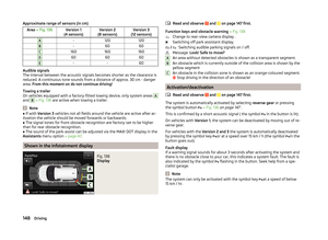 151
151 152
152 153
153 154
154 155
155 156
156 157
157 158
158 159
159 160
160 161
161 162
162 163
163 164
164 165
165 166
166 167
167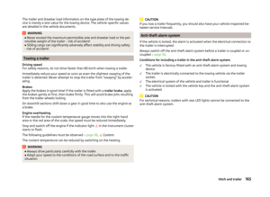 168
168 169
169 170
170 171
171 172
172 173
173 174
174 175
175 176
176 177
177 178
178 179
179 180
180 181
181 182
182 183
183 184
184 185
185 186
186 187
187 188
188 189
189 190
190 191
191 192
192 193
193 194
194 195
195 196
196 197
197 198
198 199
199 200
200 201
201 202
202 203
203 204
204 205
205 206
206 207
207 208
208 209
209 210
210 211
211 212
212 213
213 214
214 215
215 216
216 217
217 218
218 219
219 220
220 221
221 222
222 223
223 224
224 225
225 226
226 227
227 228
228 229
229 230
230 231
231 232
232 233
233 234
234 235
235 236
236 237
237 238
238 239
239 240
240 241
241 242
242 243
243 244
244 245
245 246
246 247
247