Page 177 of 204

CAUTION■Do not tow start the engine – there is a risk of damaging the engine and the
catalytic converter. The battery from another vehicle can be used as a jump-
start aid » page 172 , Jump-starting .■
If the gearbox no longer contains any oil, your vehicle must only be towed
with the front axle raised clear of the ground or on a breakdown vehicle or
trailer.
■
To protect both vehicles when tow-starting or towing, the tow rope should
be elastic. Thus one should only use plastic fibre rope or a rope made out of a
similarly elastic material.
■
There is always a risk of excessive stresses and damage resulting at the
points to which you attach the tow rope or tow bar when you attempt to tow a
vehicle which is not standing on a paved road.
■
Attach the tow rope or the tow bar to the towing eyes » page 174 , Front
towing eye or » page 174 , Rear towing eye to the detachable ball head of the
towing equipment » page 126 .
Note
We recommend using a tow rope from ŠKODA Original Accessories, which is
available from a ŠKODA Partner.
Front towing eye
Fig. 155
Removing the cap / installing the towing eye
Read and observe
and on page 173 first.
›
Press the cover in the arrow area » Fig. 155 -
.
The cover comes loose.
›
Remove the cap from the front bumper and leave it hanging on the vehicle.
› Screw in the towing eye by hand up to the stop
» Fig. 155 - .
For tightening purposes, we recommend, for example, using the wheel
wrench, towing eye from another vehicle or a similar object that can be pushed
through the eye.›
After unscrewing the cap of the towing eye, insert the cap in the lower area
and then press the opposite side of the cap.
The cap must engage firmly.
WARNINGThe towing eye must always be screwed in fully and firmly tightened, oth-
erwise the towing eye can tear when towing in or tow-starting.
Rear towing eye
Fig. 156
Rear towing eye
Read and observe and on page 173 first.
The rear towing eye is located below the rear bumper on the right » Fig. 156.
Vehicles with a tow hitch
Read and observe
and on page 173 first.
The removable towing ball may be fitted and used for towing on vehicles with
a factory fitted tow hitch » page 126, Hitch and trailer .
Towing the vehicle using the towing device is a viable alternative solution to
using the towing eye.
CAUTION
The detachable ball rod and/or the vehicle can be damaged if an unsuitable
tow bar is used. 174Do-it-yourself
Page 178 of 204

NoteThe detachable ball rod must always be in the vehicle so that it can be used for
towing, if necessary.Fuses and light bulbs
Fuses
Introduction
This chapter contains information on the following subjects:
Fuses in the dash panel
176
Fuses in the engine compartment
177
Individual electrical circuits are protected by fuses.
› Before replacing a fuse, switch off the ignition and the appropriate consumer
› Find out which fuse belongs to the component that is not operat-
ing » page 176 , Fuses in the dash panel or » page 177 , Fuses in the engine
compartment .
› Take the plastic clip out of its fixture in the cover of the fuse box, place it on
the relevant fuse and pull it out.
Fuse colourMaximum amperagelight brown5dark brown7.5red10blue15yellow20white25green30WARNINGAlways read and observe the warnings before completing any work in the
engine compartment » page 145.
CAUTION
■
“Never repair” fuses or replace them with a fuse of a higher amperage –
there is a risk of fire. This may also cause damage at another part of the elec-
trical system.■
A blown fuses is recognisable by the molten metal strip. Replace the faulty
fuse with a new one of the same amperage.
■
If a newly inserted fuse burns through again, then a specialist should be con-
sulted immediately.
175Fuses and light bulbs
Page 179 of 204

Note■We recommend always carrying replacement fuses in the vehicle. A box of
replacement fuses can be purchased from ŠKODA Original Accessories.■
There can be multiple power consuming devices for one fuse.
■
A single consumer may use several fuses.
Fuses in the dash panel
Fig. 157
Underside of the dash panel: Dis-
tribution board cover.
Fig. 158
Schematic representation of the fuse box for vehicles with left-
hand steering/right-hand steering
Read and observe
and on page 175 first.
The fuses are located on the left side of the dash panel behind a cover.
› Carefully remove the cover in the direction of the arrow
» Fig. 157.
› After the fuse has been replaced, replace the cover in the dash panel in the
opposite direction of the arrow so that the guide lugs are guided into the
openings of the dash panel. Close the cover until it clicks into place.
Fuse assignment in the dash panelNo.Consumer1S-contact2START-STOP, air-conditioning system3Instrument cluster, headlamp beam adjustment4Control unit for ABS, button for START STOP5Petrol engine: Speed regulating system6Reversing light (manual gearbox)7Ignition, engine control unit, automatic gearbox8Brake pedal switch, clutch pedal switch9Operating controls for the heating, control unit for air conditioning
system, parking aid, control unit for cornering lights, radiator fan,
washing nozzles10Windscreen Wiper and Washer System11Mirror adjustment12Control unit for trailer detection13Control unit for automatic gearbox14Motor for halogen projector headlights with cornering light function15PDA navigation system16Electro-hydraulic power steering17Light switch power supply18Mirror heater19S-contact20Alarm21Reversing light, fog lights with the function CORNER
22
Operating controls for the heating, control unit for air conditioning
system, parking aid, mobile phone, instrument cluster, steering an-
gle sender, ESC, vehicle voltage control unit, multifunction steering
wheel23Interior lighting, storage compartment and luggage compartment,
side lights24Central control unit25Seat heaters26Rear window wiper 176Do-it-yourself
Page 180 of 204

No.Consumer27Telephone preinstallation28Petrol engine: AKF valve, Diesel engine: Control flap29Injection, coolant pump30Fuel pump, ignition, Cruise control system, operation of PTC relay31Lambda probe32High pressure fuel pump, pressure valve33Engine control unit34Engine control unit, vacuum pump35Daytime running lights/radio for vehicles with START-STOP36Main beam37Rear fog light, DC/DC converter START-STOP38Fog lights39Air blower for heating40-41Not assigned42Rear window heater43Horn44Windscreen wipers45Central control unit for convenience system46Engine control unit, fuel pump47Cigarette lighter, power socket in the luggage compartment48ABS, START-STOP (DC/DC) converter, ESC49Turn signal lights, brake lights50START-STOP (DC/DC) transformer, radio51Electrical power window (front and rear) - left side52Electrical power window (front and rear) - right side53Parking light = left side, electrical sliding/tilting roof54START-STOP (instrument cluster), alarm55Control unit for automatic gearbox56Headlight cleaning system, parking light - right side57Left low beam, headlight range adjustment58Low beam on the rightFuses in the engine compartmentFig. 159
Vehicle battery: Distribution board cover.
Fig. 160
Schematic representation of fuse
box in engine compartment
Read and observe and on page 175 first.
› Press the securing clips on the fuse box cover together at the same time in
the direction of arrow
A
» Fig. 159 and remove the cover in the direction of
arrow
B
.
› Release the fixtures in the openings
C
using a flat screwdriver and fold the
cover upwards in direction of arrow
D
.
Fuse assignment in engine compartment
No.Consumer1Generator2Not assigned3Interior4Electrical auxiliary heating system5Interior 177Fuses and light bulbs
Page 181 of 204

No.Consumer6Glow plugs, radiator fan7Electro-hydraulic power steering8ABS or TCS or ESC9Radiator fan10Automatic gearbox11ABS or TCS or ESC12Central control unit13Electrical auxiliary heating system
Note
Fuses 1-7 are replaced by a specialist garage.
Replacing bulbs
Introduction
This chapter contains information on the following subjects:
Headlights
179
Changing the low beam and high beam bulb (halogen headlights)
179
Changing the high beam bulb (halogen projector headlights)
179
Changing the high beam bulb (halogen projector headlights)
180
Changing the front turn signal bulb
180
Changing the front parking light bulb
180
Fog lights and daytime running lights
180
Fog light, Roomster Scout
181
Replacing the bulb for the licence plate light
181
Rear Light
181
Some manual skills are required to change a bulb. For this reason, we recom-
mend having bulbs replaced by a specialist garage or seeking other expert help
in the event of any uncertainties.
› Switch off the ignition and all of the lights before replacing a bulb.
› Faulty bulbs must only be replaced with the same type of bulbs. The designa-
tion is located on the light socket or the glass bulb.
› A stowage compartment for replacement bulbs is located in a plastic box in
the spare wheel or underneath the floor covering in the boot.
WARNING■ Always read and observe the warnings before completing any work in the
engine compartment » page 145.■
Accidents can be caused if the road in front of the vehicle is not suffi-
ciently illuminated and the vehicle cannot or can only be seen with difficul-
ty by other road users.
■
Bulbs H7 and H4 are pressurised and may burst when changed - there is a
risk of injury. We therefore recommended wearing gloves and safety
glasses when changing a bulb.
■
Switch off the respective vehicle light when changing the bulb.
CAUTION
■ Do not take hold of the glass bulb with naked fingers (even the smallest
amount of dirt reduces the working life of the light bulb). Use a clean cloth,
napkin, or similar.■
When removing and installing the number plate light and tail light make sure
that the paintwork of the vehicle and the tail light are not damaged.
Note
■ This Owner's Manual only describes the replacement of bulbs where it is pos-
sible to replace the bulbs on your own without any complications arising. Other
bulbs must be replaced by a specialist garage.■
We recommend that a box of replacement bulbs always be carried in the ve-
hicle. Replacement bulbs can be purchased from ŠKODAOriginal Accessories.
■
We recommend having the headlight settings checked by a specialist garage
after replacing a bulb in the main beam, low beam or fog lights.
■
Visit a specialist garage if an LED is faulty.
178Do-it-yourself
Page 182 of 204

HeadlightsFig. 161
Bulb arrangement: Halogen headlights/halogen projector head-
lights
Read and observe
and on page 178 first.
Bulb arrangement in the Halogen headlamp
A
- low beam, main beam and side lights
B
- front turn signal light
Bulb arrangement in the Halogen projector headlights
1
- low beam / low and main beam
2
- parking light / parking and main beam lights
3
- turn signal lights
Changing the low beam and high beam bulb (halogen headlights)
Fig. 162
Removing bulbs for low and
main beam
Read and observe and on page 178 first.
›
Remove the protective cap
A
» Fig. 161 on page 179 .
›Remove the connector from the bulb, unlock the securing clip and remove
the bulb in the direction of the arrow » Fig. 162.›
Insert a new light bulb in such a way that the fixing lugs of the bulb socket fit
in the recesses of the reflector.
›
Lock the circlip and insert the connector in the bulb.
›
Fit the protective cap
A
.
Changing the high beam bulb (halogen projector headlights)
Fig. 163
Removing the bulb for the low
beam
Read and observe and on page 178 first.
›
Remove the protective cap
1
» Fig. 161 on page 179 .
›
Turn the socket with the bulb to the stop in the direction of the ar-
row » Fig. 163 and remove it.
›
Replace the bulb, insert the connector and new bulb and turn to the stop in
the opposite direction to that of the arrow.
›
Fit the protective cover
1
.
179Fuses and light bulbs
Page 183 of 204
Fig. 164
Removing the bulb for the main
beam
Read and observe and on page 178 first.
›
Remove the protective cap
2
» Fig. 161 on pag")
Changing the high beam bulb (halogen projector headlights)Fig. 164
Removing the bulb for the main
beam
Read and observe and on page 178 first.
›
Remove the protective cap
2
» Fig. 161 on page 179 .
›
Turn the socket with the bulb to the stop in the direction of the ar-
row » Fig. 164 and remove it.
›
Replace the bulb, insert the connector and new bulb and turn to the stop in
the opposite direction to that of the arrow.
›
Fit the protective cover
2
.
Changing the front turn signal bulb
Read and observe
and on page 178 first.
›
Remove the bulb holder
B
» Fig. 161 on page 179 or the bulb holder
3
to the
stop in an anti-clockwise direction and remove with the bulb for the turn sig-
nal.
›
Replace the bulb, insert the bulb holder with the new bulb and turn clock-
wise to the stop.
Changing the front parking light bulb
Read and observe
and on page 178 first.
›
Remove the protective cap
A
» Fig. 161 on page 179 or
2
.
›
Grasp the lamp holder and remove it from the bulb housing.
›
Replace the light bulb and insert the lamp holder back into the headlamp
with the bulb.
›
Fit the protective cap.
Fog lights and daytime running lightsFig. 165
Front bumper: Protective grille/removing the fog light
Read and observe
and on page 178 first.
Bulb arrangement » Fig. 165
Light bulb for daytime driving light
Light bulb for fog lights
Removing the cap
›
Grasp the protective grille in the areas marked by the arrows » Fig. 165 -
and remove the cover in the direction of the arrow.
Replacing light bulbs for fog lights/daytime running lights
›
Insert your hand into the opening in the protective grille and press the
catch » Fig. 165 -
in the direction of the arrow.
›
Remove the fog lamp.
›
Turn the connector with the bulb in
counter-clockwise up to the stop and re-
move.
›
Replace the bulb, insert the holder with the new bulb and turn clockwise to
the stop.
›
To re-install the fog light, first of all place the fog light with the lug on the
side opposite the licence plate.
›
Press in the fog lamp on the side closest to the licence plate.
›
Insert the cap, beginning with the lug on the side opposite the license plate.
›
Press in the cap on the side facing the license plate. The cap must engage
firmly.
AB180Do-it-yourself
Page 184 of 204

Fog light, Roomster ScoutFig. 166
Front bumper: Roomster Scout
Fig. 167
Front bumper: Fog lights/fog lights: Replacing the light bulb
Read and observe
and on page 178 first.
Removing the cap and fog light
›
Insert the tool » page 166, Vehicle tool kit into the opening above the fog
light » Fig. 166 and remove the cover.
›
Unscrew the screws » Fig. 167 -
with the screwdriver
» page 166, Vehicle
tool kit .
›
Remove the fog lamp.
Changing light bulbs and installing fog lights
›
Press the locking tab
1
» Fig. 167 on the connector
A
and remove the con-
nector from the bulb holder
B
.
›
Turn the bulb holder
B
and bulb in the direction of the arrow to the stop and
remove.
›
Replace the bulb, insert the bulb holder and new bulb and turn in the oppo-
site direction to that of the arrow to the stop.
›
Insert the plug
A
into the socket
B
.
› Retighten the screws and insert the cap. The cap must engage firmly.
Replacing the bulb for the licence plate light
Fig. 168
Remove the licence plate light
Read and observe and on page 178 first.
›
Open the tailgate and unscrew the glass cover
» Fig. 168.
›
Remove the faulty bulb from the holder and insert a new one.
›
Replace the glass cover and push in until the stop. Make sure that you install
the rubber seal in the right direction.
›
Slightly screw the glass cover.
Rear Light
Fig. 169
Removing the tail light assembly/disconnecting the plug connec-
tion
181Fuses and light bulbs
 1
1 2
2 3
3 4
4 5
5 6
6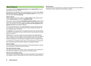 7
7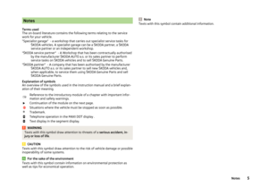 8
8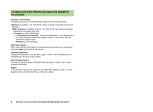 9
9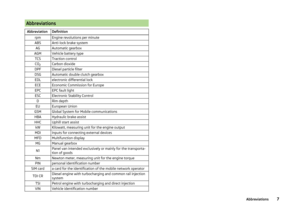 10
10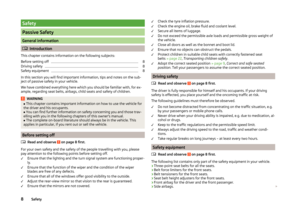 11
11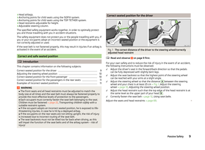 12
12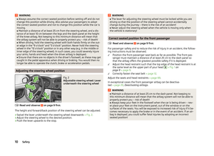 13
13 14
14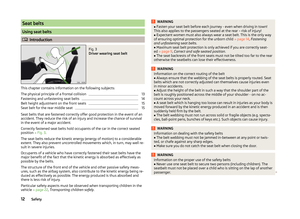 15
15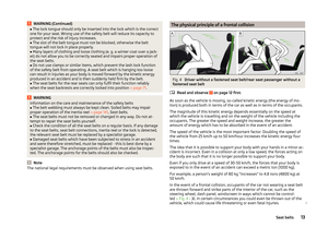 16
16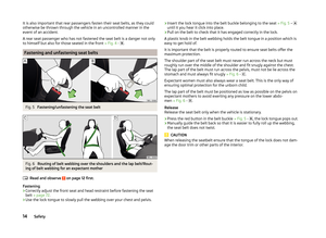 17
17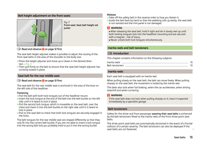 18
18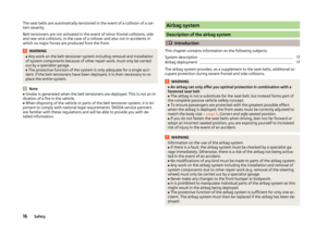 19
19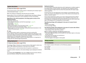 20
20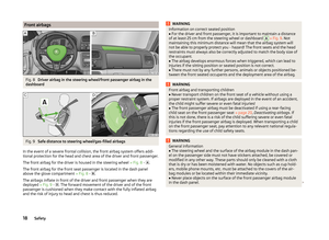 21
21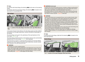 22
22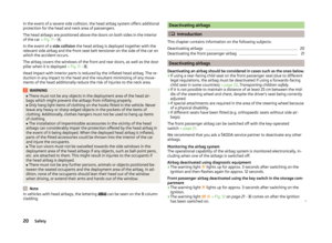 23
23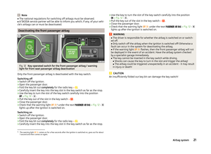 24
24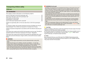 25
25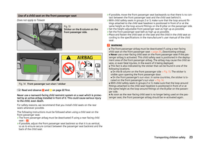 26
26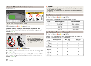 27
27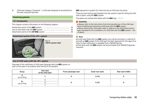 28
28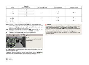 29
29 30
30 31
31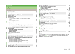 32
32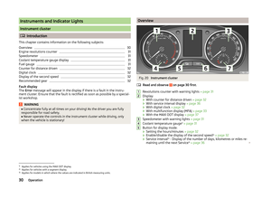 33
33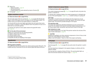 34
34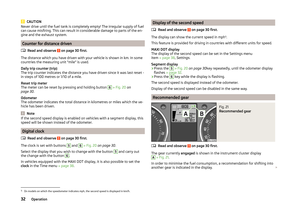 35
35 36
36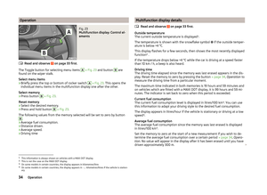 37
37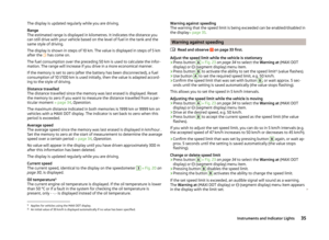 38
38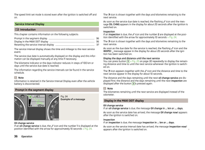 39
39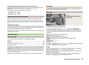 40
40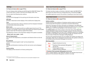 41
41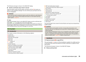 42
42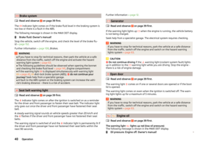 43
43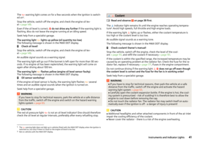 44
44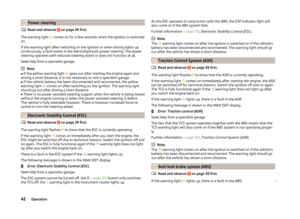 45
45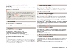 46
46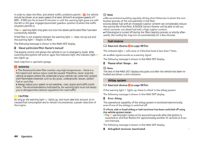 47
47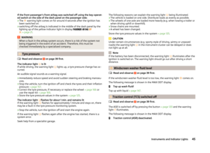 48
48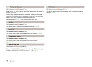 49
49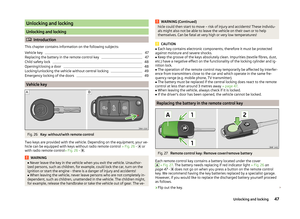 50
50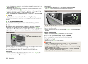 51
51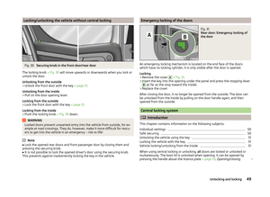 52
52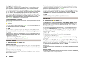 53
53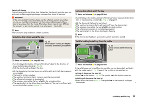 54
54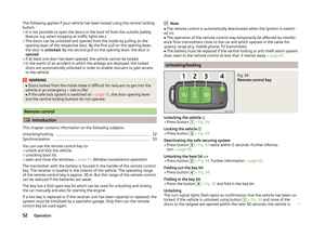 55
55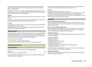 56
56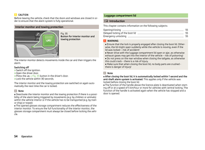 57
57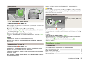 58
58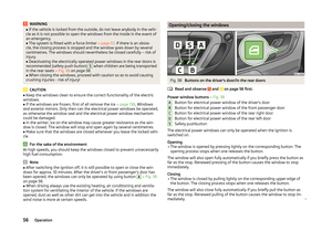 59
59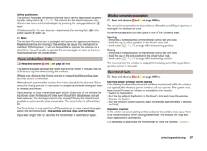 60
60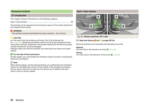 61
61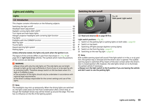 62
62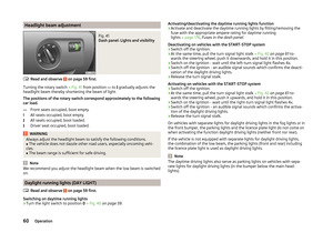 63
63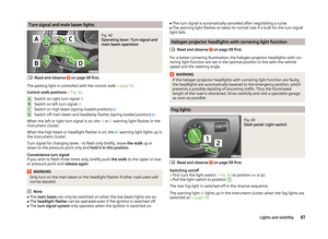 64
64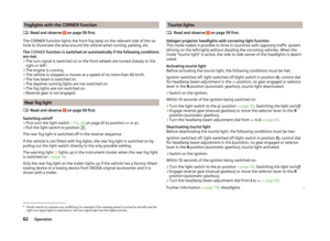 65
65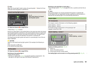 66
66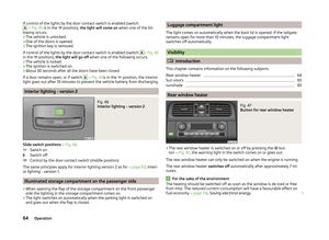 67
67 68
68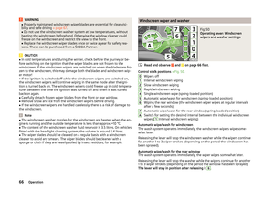 69
69 70
70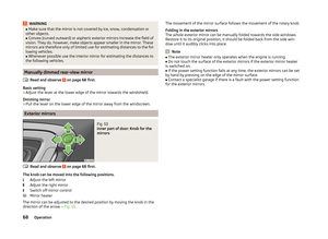 71
71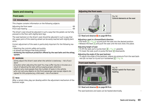 72
72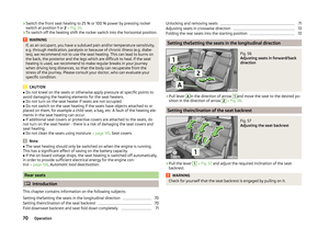 73
73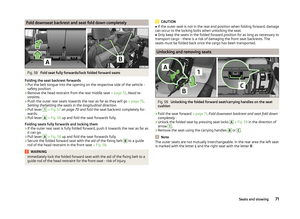 74
74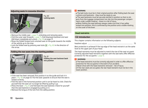 75
75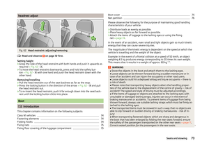 76
76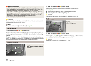 77
77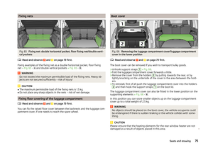 78
78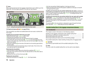 79
79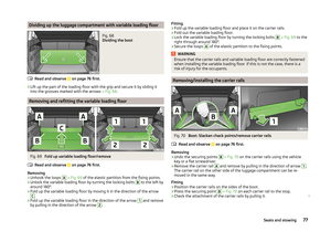 80
80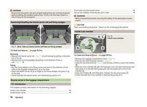 81
81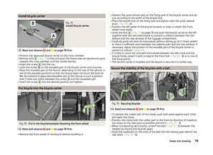 82
82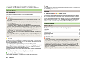 83
83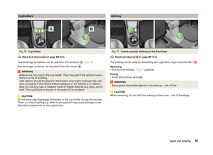 84
84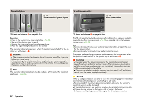 85
85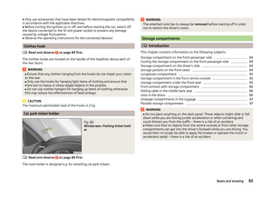 86
86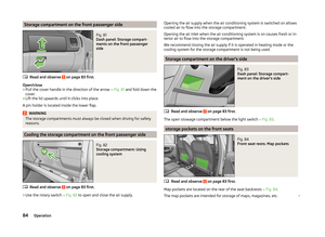 87
87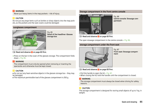 88
88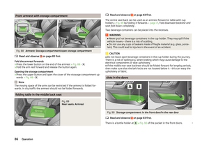 89
89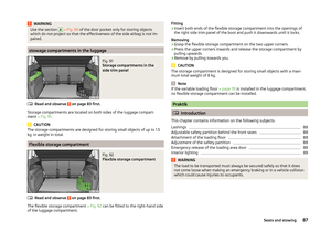 90
90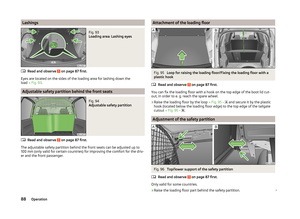 91
91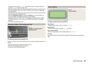 92
92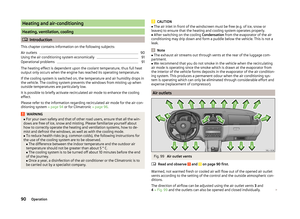 93
93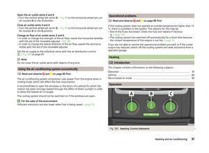 94
94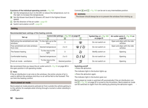 95
95 96
96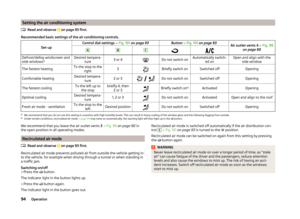 97
97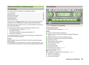 98
98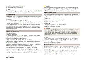 99
99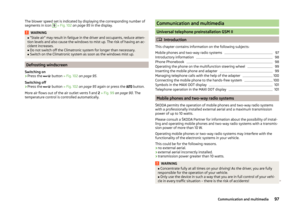 100
100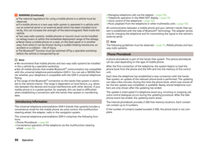 101
101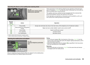 102
102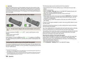 103
103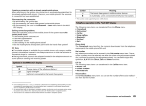 104
104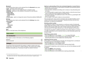 105
105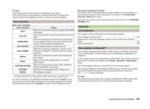 106
106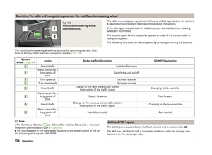 107
107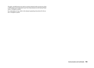 108
108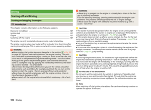 109
109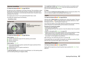 110
110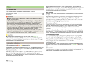 111
111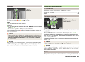 112
112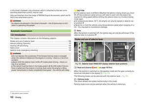 113
113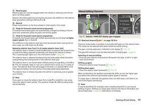 114
114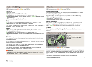 115
115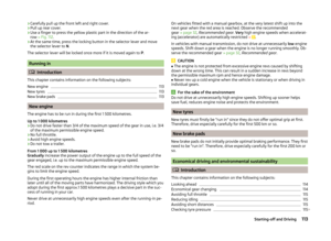 116
116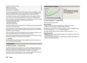 117
117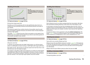 118
118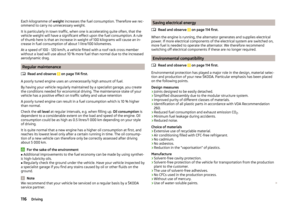 119
119 120
120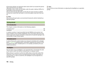 121
121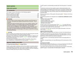 122
122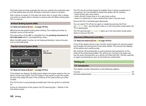 123
123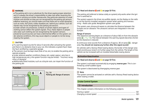 124
124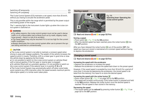 125
125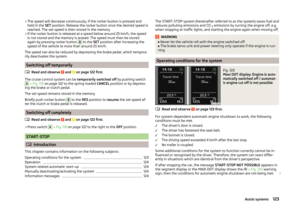 126
126 127
127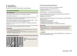 128
128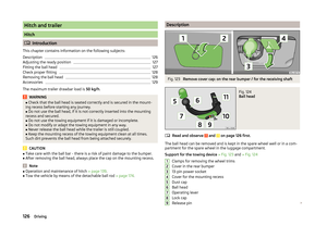 129
129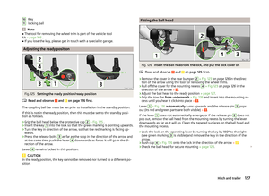 130
130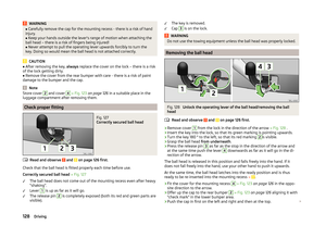 131
131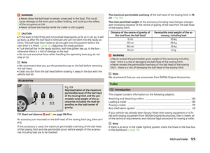 132
132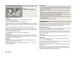 133
133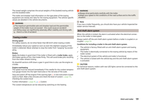 134
134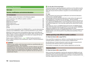 135
135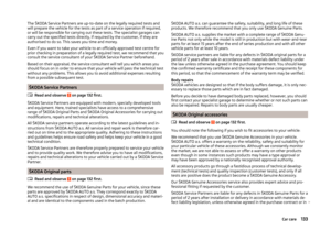 136
136 137
137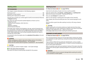 138
138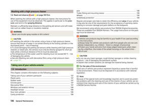 139
139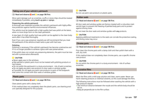 140
140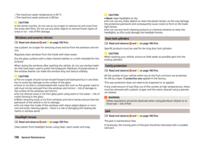 141
141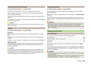 142
142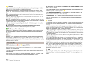 143
143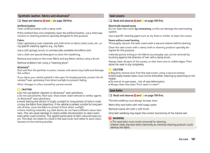 144
144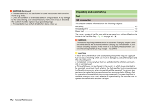 145
145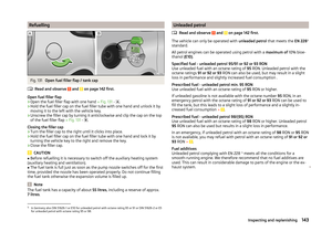 146
146 147
147 148
148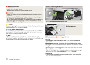 149
149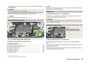 150
150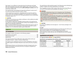 151
151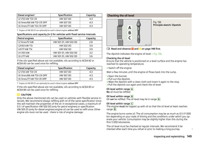 152
152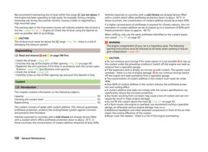 153
153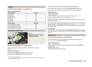 154
154 155
155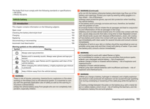 156
156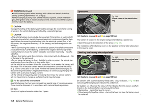 157
157 158
158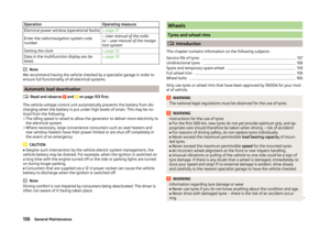 159
159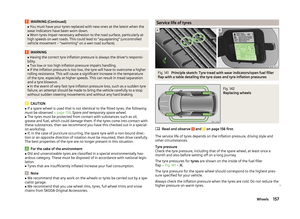 160
160 161
161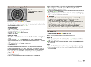 162
162 163
163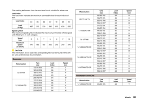 164
164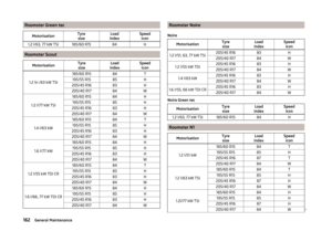 165
165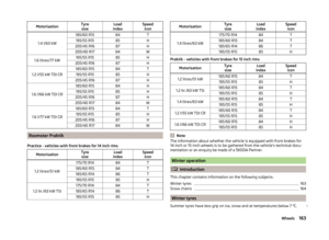 166
166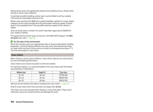 167
167 168
168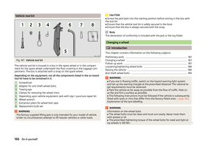 169
169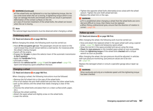 170
170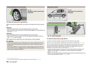 171
171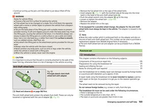 172
172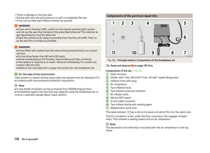 173
173 174
174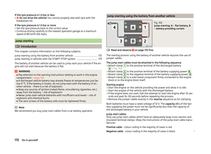 175
175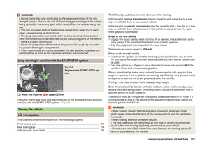 176
176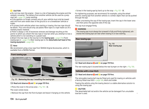 177
177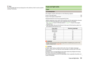 178
178 179
179 180
180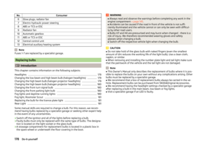 181
181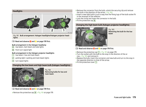 182
182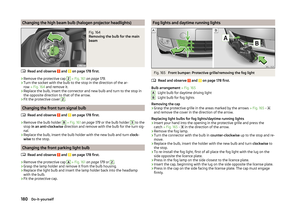 183
183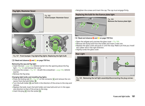 184
184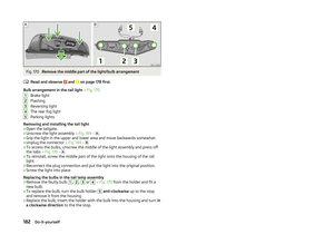 185
185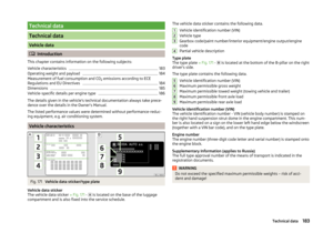 186
186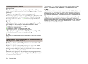 187
187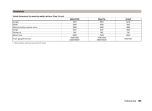 188
188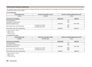 189
189 190
190 191
191 192
192 193
193 194
194 195
195 196
196 197
197 198
198 199
199 200
200 201
201 202
202 203
203