Page 89 of 204

Front armrest with storage compartmentFig. 88
Armrest: Storage compartment/open storage compartment
Read and observe
on page 83 first.
Fold the armrest forwards
›
Press the lower button on the end of the armrest » Fig. 88 -
.
›
Fold the arm rest forward and release the button again.
Opening the storage compartment
›
Press the upper button and open the cover of the stowage compartment up-
wards » Fig. 88 -
.
Note
The moving space of the arms can be restricted if the armrest is folded for-
wards. In city traffic the armrest should not be folded forwards.
folding table in the middle back seat
Fig. 89
Rear seats: Armrest
Read and observe on page 83 first.
The centre seat back can be used as an armrest forward or table with cup
holders » Fig. 89 by folding it forwards » page 71, Fold downseat backrest and
seat fold down completely .
Two beverage containers can be placed into the recesses.
WARNING■ Never put hot beverage containers in the cup holder. They may spill if the
vehicle moves – there is a risk of scalding.■
Do not use any cups or beakers made of fragile material (e.g. glass, porce-
lain). This could lead to injuries in the event of an accident.
CAUTION
■ Do not leave open beverage containers in the cup holder during the journey.
There is a risk of spilling e.g. when braking which may cause damage to the
electrical components or seat upholstery.■
If the middle rear seat backrest should be folded forward for lengthy periods,
then make sure that the belt locks are not located below it - this can warp the
upholstery or fabric.
slots in the doors
Fig. 90
Storage compartment: in the front door/in the rear door
Read and observe
on page 83 first.
There is a bottle holder at
B
» Fig. 90 of the pocket in the front doors.
86Operation
Page 90 of 204

WARNINGUse the section A » Fig. 90 of the door pocket only for storing objects
which do not project so that the effectiveness of the side airbag is not im-
paired.
stowage compartments in the luggage
Fig. 91
Storage compartments in the
side trim panel
Read and observe on page 83 first.
Storage compartments are located on both sides of the luggage compart-
ment » Fig. 91 .
CAUTION
The storage compartments are designed for storing small objects of up to 1.5
kg. in weight in total.
Flexible storage compartment
Fig. 92
Flexible storage compartment
Read and observe on page 83 first.
The flexible storage compartment » Fig. 92 can be fitted to the right-hand side
of the luggage compartment.
Fitting›Insert both ends of the flexible storage compartment into the openings of
the right side trim panel of the boot and push it downwards until it locks.
Removing›
Grasp the flexible storage compartment on the two upper corners.
›
Press the upper corners inwards and release the storage compartment by
pulling upwards.
›
Remove by pulling towards you.
CAUTION
The storage compartment is designed for storing small objects with a maxi-
mum total weight of 8 kg.
Note
If the variable loading floor » page 76 is installed in the luggage compartment,
no flexible storage compartment can be installed.
Praktik
Introduction
This chapter contains information on the following subjects:
Lashings
88
Adjustable safety partition behind the front seats
88
Attachment of the loading floor
88
Adjustment of the safety partition
88
Emergency release of the loading area door
89
Interior lighting
89WARNINGThe load to be transported must always be secured safely so that it does
not come loose when making an emergency braking or in a vehicle collision
which could cause injuries to occupants.87Seats and stowing
Page 91 of 204

LashingsFig. 93
Loading area: Lashing eyes
Read and observe on page 87 first.
Eyes are located on the sides of the loading area for lashing down the
load » Fig. 93 .
Adjustable safety partition behind the front seats
Fig. 94
Adjustable safety partition
Read and observe on page 87 first.
The adjustable safety partition behind the front seats can be adjusted up to
100 mm (only valid for certain countries) for improving the comfort for the driv-
er and the front passenger.
Attachment of the loading floorFig. 95
Loop for raising the loading floor/Fixing the loading floor with a
plastic hook
Read and observe
on page 87 first.
You can fix the loading floor with a hook on the top edge of the boot lid cut-
out, in order to e. g. reach the spare wheel.
›
Raise the loading floor by the loop » Fig. 95 -
and secure it by the plastic
hook (located below the loading floor edge) to the top edge of the tailgate
cutout » Fig. 95 -
.
Adjustment of the safety partition
Fig. 96
Top/lower support of the safety partition
Read and observe
on page 87 first.
Only valid for some countries.
›
Raise the loading floor part behind the safety partition.
88Operation
Page 92 of 204

›Undo and remove a bolt
» Fig. 96 - on either side in the upper body and
one bolt » Fig. 96 - in the lower area.›
Move the safety partition into the required position. Ensure it is always move
the same distance- the same number of holes on both sides both upwards
and downwards.
›
On each side in the upper area of the body, undo and remove a bolt and undo
and remove a bolt in the lower area.
›
Have the tightening torque of the bolts checked with a torque wrench as
soon as possible. The tightening torque must be 20 Nm.
›
Change the position of the cover of the luggage compartment floor behind
the safety partition so that it lines up with the new position of the safety
partition.
›
Fold back the loading floor part.
Emergency release of the loading area door
Fig. 97
Emergency unlocking of the
loading area door
Read and observe on page 87 first.
If there is a fault in the central locking, you can unlock the loading area door as
follows:
›
Pull the control cable towards you and pull on it.
›
Press on the loading area door to open it.
›
Press the control cable back again.
Interior lightingFig. 98
Interior lighting
Read and observe on page 87 first.
Switching on
›
Move the cover glass to the position
» Fig. 98.
Switching off
›
Move the cover glass to the O » Fig. 98 position.
Door contact setting
›
Move the cover glass to the middle position
» Fig. 98 .
Note
We recommend you have the bulb replacement performed by a specialist ga-
rage.89Seats and stowing
Page 93 of 204

Heating and air-conditioning
Heating, ventilation, cooling
Introduction
This chapter contains information on the following subjects:
Air outlets
90
Using the air conditioning system economically
91
Operational problems
91
The heating effect is dependent upon the coolant temperature, thus full heat
output only occurs when the engine has reached its operating temperature.
If the cooling system is switched on, the temperature and air humidity drops in
the vehicle. The cooling system prevents the windows from misting up when
outside temperatures are particularly low.
It is possible to briefly activate recirculated air mode to enhance the cooling
effect.
Please refer to the information regarding recirculated air mode for the air-con-
ditioning system » page 94 or for Climatronic » page 96.
WARNING■
For your own safety and that of other road users, ensure that all the win-
dows are free of ice, snow and misting. Please familiarize yourself about
how to correctly operate the heating and ventilation systems, how to de-
mist and defrost the windows, as well as with the cooling mode.■
To reduce health risks (e.g. common colds), the following instructions for
the use of the cooling system are to be observed. ■The difference between the indoor temperature and the outdoor air
temperature should not be greater than about 5 ° C.
■ The cooling system is to be turned off about 10 minutes before the end
of the journey.
■ Once a year, a disinfection of the air conditioner or the Climatronic is to
be carried out by a specialist company.
CAUTION■ The air inlet in front of the windscreen must be free (e.g. of ice, snow or
leaves) to ensure that the heating and cooling system operates properly.■
After switching on the cooling Condensation from the evaporator of the air
conditioning may drip down and form a puddle below the vehicle. This is not a
leak.
Note
■ The exhaust air streams out through vents at the rear of the luggage com-
partment.■
We recommend that you do not smoke in the vehicle when the recirculating
air mode is operating since the smoke which is drawn at the evaporator from
the interior of the vehicle forms deposits in the evaporator of the air condition-
ing system. This produces a permanent odour when the air conditioning sys-
tem is operating which can only be eliminated through considerable effort and
expense (replacement of compressor).
Air outlets
Fig. 99
Air outlet vents
Read and observe
and on page 90 first.
Warmed, not warmed fresh or cooled air will flow out of the opened air outlet vents according to the setting of the control and the outside atmospheric con-
ditions.
The direction of airflow can be adjusted using the air outlet vents 3 and
4 » Fig. 99 and the outlets can also be opened and closed individually.
90Operation
Page 94 of 204
 » Fig. 99 or the horizontal wheel (air out-
let nozzles 4) to the
position.
Close air outlet vents 3 and 4›
Turn th")
Open the air outlet vents 3 and 4›Turn the vertical wheel (air vents 3) » Fig. 99 or the horizontal wheel (air out-
let nozzles 4) to the
position.
Close air outlet vents 3 and 4›
Turn the vertical wheel (air vents 3) » Fig. 99 or the horizontal wheel (air out-
let nozzles 4) to the 0 position.
Change air flow of air outlet vents 3 and 4
›
In order to change the strength of the air flow, swivel the horizontal lamellas
with the aid of the moveable adjuster » Fig. 99.
›
In order to change the lateral direction of the air flow, swivel the vertical la-
mellas with the aid of the moveable adjuster.
Set the air supply to the individual vents with the air distribution control
C
» Fig. 100 on page 91 .
Note
Do not cover the air outlet vents with objects of any kind.
Using the air conditioning system economically
Read and observe
and on page 90 first.
The air conditioning system compressor uses power from the engine when incooling mode, which will affect the fuel consumption.
It recommended to open the windows or the doors of a vehicle for which the
interior has been strongly heated through the effect of direct sunlight in order
to allow the heated air to escape.
The cooling system should not be switched on if the windows are open.
For the sake of the environment
Pollutant emissions are also lower when fuel is being saved » page 113.Operational problems
Read and observe
and on page 90 first.
If the cooling system does not operate at outside temperatures higher than +5°C, there is a problem in the system. The reasons for this may be.
› One of the fuses has blown. Check the fuse and replace if necessa-
ry » page 175 .
› The cooling system has switched off automatically for a short time because
the coolant temperature of the engine is too hot » page 31.
If you are not able to resolve the operational problem yourself, or if the cooler
output has reduced, switch off the cooling system and seek assistance from a
specialist garage.
Heating
Introduction
This chapter contains information on the following subjects:
Operation
91
Setting
92
Recirculated air mode
92
Operation
Fig. 100
Heating: Control elements
91Heating and air-conditioning
Page 95 of 204

Set the blower level (level")
Functions of the individual operating controls » Fig. 100
Set the temperature (turn to the left: to reduce the temperature, turn to
the right: to increase the temperature)
Set the blower level (level 0: blowers off, level 4: the highest blower
speed)
Set the direction of the air outlet » page 90
Switch recirculation on/off » page 92ABCControls A and C » Fig. 100 can be set to any intermediate position.WARNINGThe blower should always be on to prevent the windows from misting up.
Setting
Recommended basic settings of the heating controls.Set-upControl dial settings » Fig. 100 on page 91Symbol Key » Fig. 100
on page 91Air outlet vents 4 » Fig. 99 on
page 90ABCDefrosting the windshield and side
windowsTo the right up to the stop3Do not switch onOpen and align with the side windowFree windshield and side windows
from mistDesired temperature2 or 3
Do not switch onOpen and align with the side
windowThe fastest heatingTo the stop to theright3Briefly switch onOpeningComfortable heatingDesired temperature2 or 3
Do not switch onOpeningFresh air mode - ventilationTo the stop to the
leftDesired positionDo not switch onOpeningWe recommend that you leave the air outlet vents 3 » Fig. 99 on page 90 in
the open position in all operating modes.
Note
If the air distribution is set only to the windows, the entire volume of air is
used to defrost the windows and thus no air will be fed to the footwell. This
can limit the heating comfort.
Recirculated air mode
Recirculated air mode prevents polluted air from outside the vehicle getting in-
to the vehicle, for example when driving through a tunnel or when standing in
a traffic jam.
Switching on/off›Press the button.
The indicator light in the button lights up.›
Press the
button again.
The indicator light in the button goes out.
Recirculated air mode is switched off automatically if the air distribution con-
trol
C
» Fig. 100 on page 91 is turned to the
position. Recirculated air mode
can be switched on again from this setting by pressing the
button again.
92Operation
Page 96 of 204

WARNINGNever leave recirculated air mode on over a longer period of time, as “stale
air” can cause fatigue of the driver and the passengers, reduce attention
levels and also cause the windows to mist up. The risk of having an acci-
dent increases. Switch off recirculated air mode as soon as the windows
start to mist up.
Air conditioning system (manual air conditioning system)
Introduction
This chapter contains information on the following subjects:
Operation
93
Setting the air conditioning system
94
Recirculated air mode
94
The cooling system operates only if the following conditions are met. The cooling system is switched on » page 93.
The engine is running.
The outside temperature is above approximately +2 °C.
The blower switch is switched on (positions 1-4).
If the desired interior temperature can also be achieved without activating the
cooling system, fresh air mode should be selected.
If the coolant temperature is too high, the cooling system is switched off to
ensure that the engine cools down.
CAUTION
■ Under certain circumstances, air at a temperature of about 5 °C can flow out
of the vents when the cooling system is switched on.■
Lengthy and uneven distribution of the air flow out of the vents (especially
around the feet) and large differences in temperature, for example, when get-
ting out of the vehicle, can cause susceptible individuals to catch a cold.
Note
■ We recommend that you have the air conditioning system cleaned by a spe-
cialist garage once every year.■
During operation of the air conditioning, an increase in engine idle speed may
occur under certain circumstances in order to ensure sufficient heating com-
fort.
OperationFig. 101
The air conditioning system: Control elements
Read and observe
on page 93 first.
Functions of the individual operating controls » Fig. 101
Set the temperature (turn to the left: to reduce the temperature, turn to
the right: to increase the temperature)
Set the blower level (level 0: blowers off, level 4: the highest blower
speed)
Set the direction of the air outlet » page 90
Switch recirculation on/off » page 94
Switch the cooling system on/off
Note
The warning light in the symbol button lights after activation, even if not all
of the conditions for the function of the cooling system are met » page 93. The
operational readiness of the cooling system is indicated by the indicator light
in the button lighting up.ABC93Heating and air-conditioning
 1
1 2
2 3
3 4
4 5
5 6
6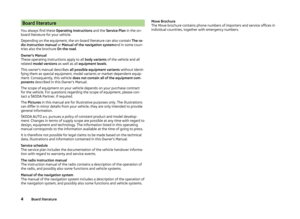 7
7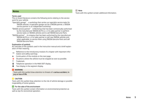 8
8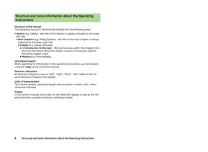 9
9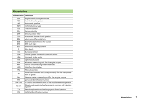 10
10 11
11 12
12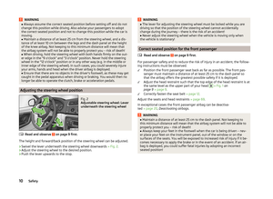 13
13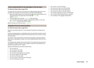 14
14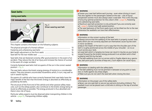 15
15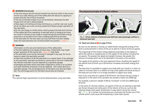 16
16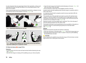 17
17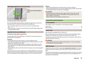 18
18 19
19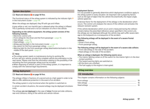 20
20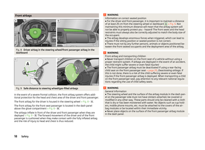 21
21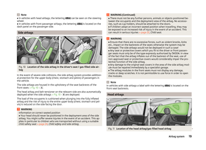 22
22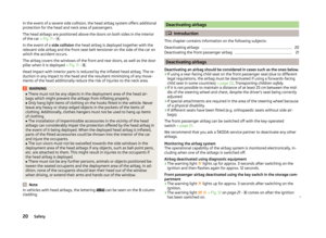 23
23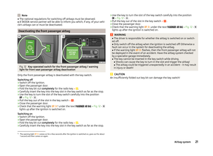 24
24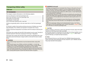 25
25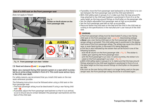 26
26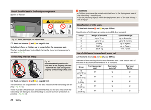 27
27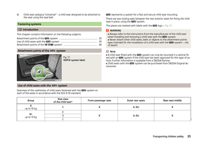 28
28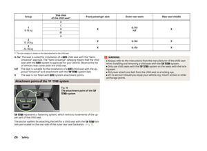 29
29 30
30 31
31 32
32 33
33 34
34 35
35 36
36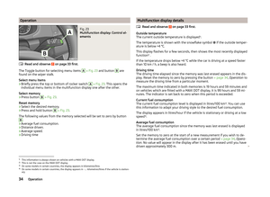 37
37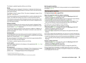 38
38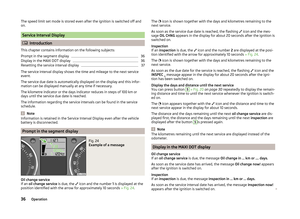 39
39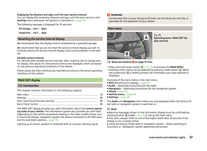 40
40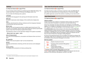 41
41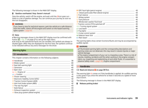 42
42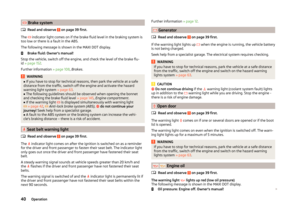 43
43 44
44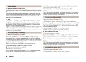 45
45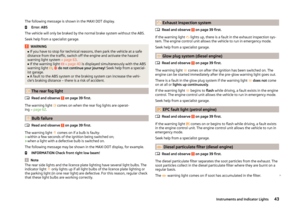 46
46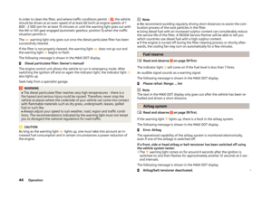 47
47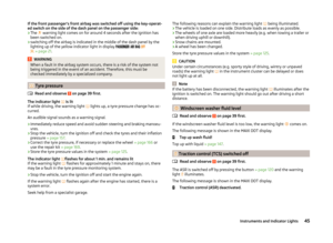 48
48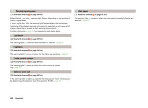 49
49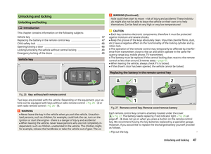 50
50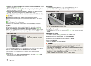 51
51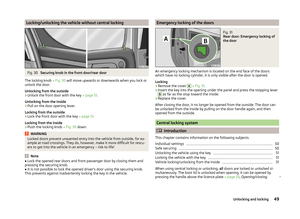 52
52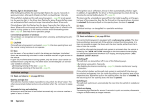 53
53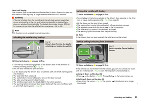 54
54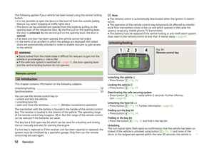 55
55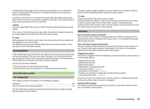 56
56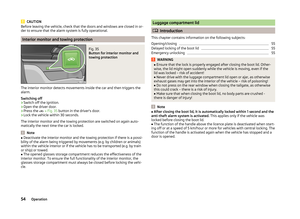 57
57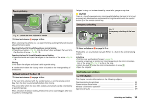 58
58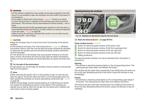 59
59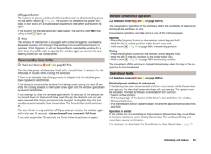 60
60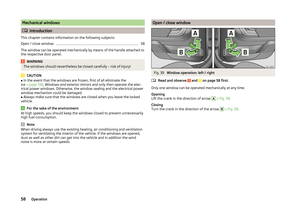 61
61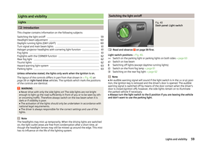 62
62 63
63 64
64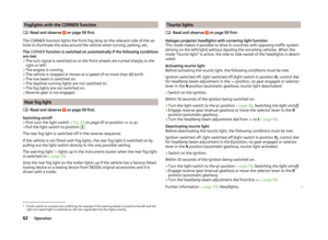 65
65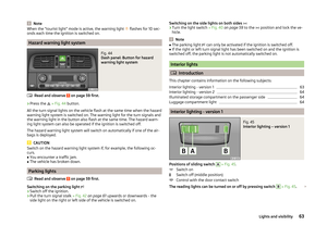 66
66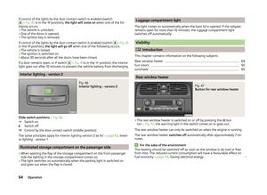 67
67 68
68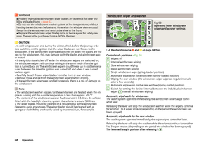 69
69 70
70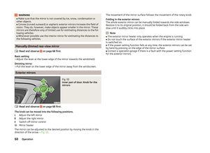 71
71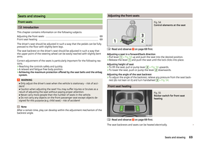 72
72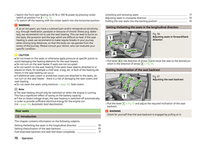 73
73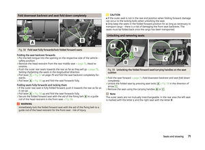 74
74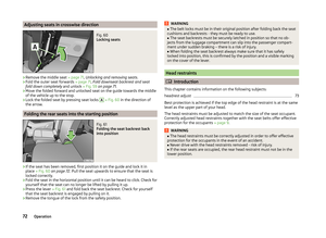 75
75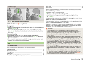 76
76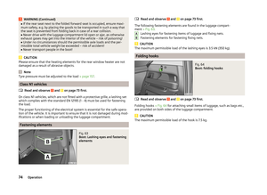 77
77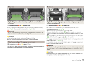 78
78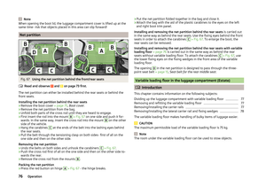 79
79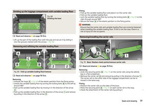 80
80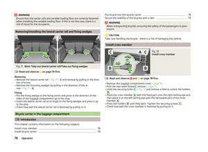 81
81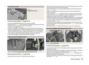 82
82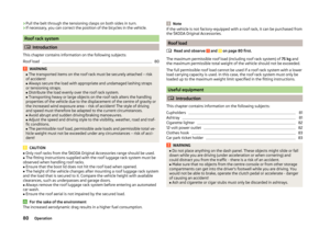 83
83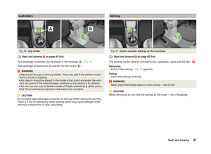 84
84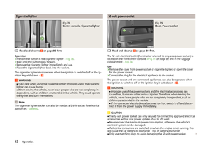 85
85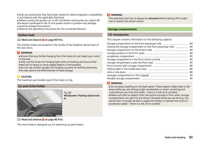 86
86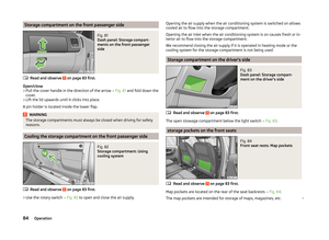 87
87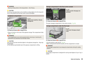 88
88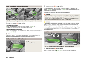 89
89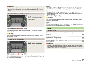 90
90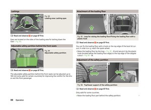 91
91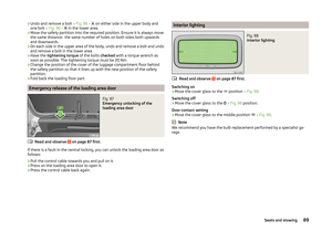 92
92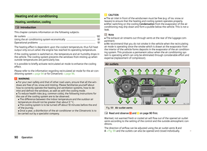 93
93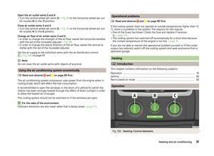 94
94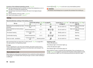 95
95 96
96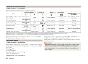 97
97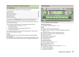 98
98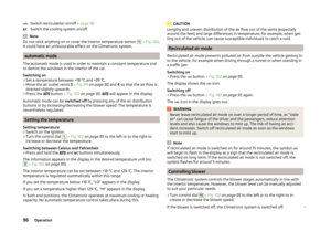 99
99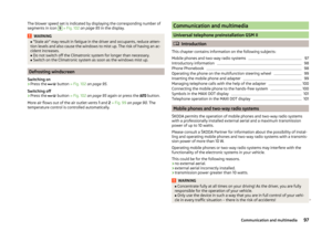 100
100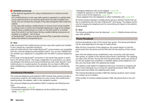 101
101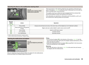 102
102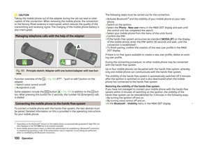 103
103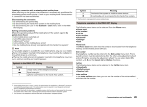 104
104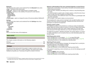 105
105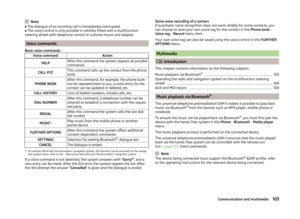 106
106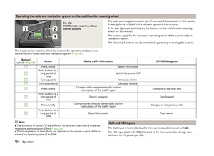 107
107 108
108 109
109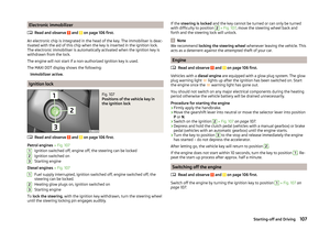 110
110 111
111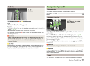 112
112 113
113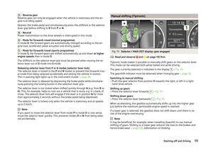 114
114 115
115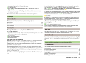 116
116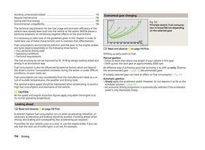 117
117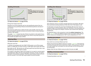 118
118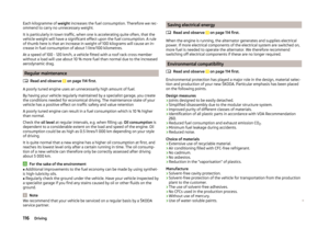 119
119 120
120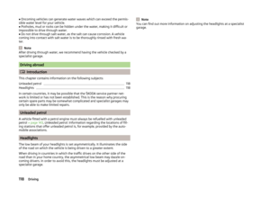 121
121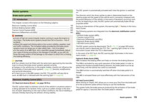 122
122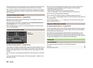 123
123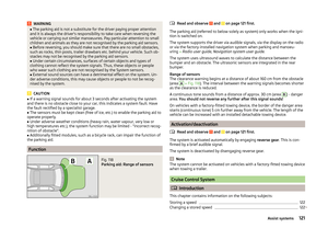 124
124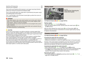 125
125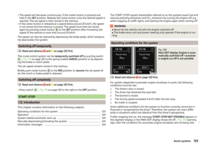 126
126 127
127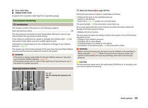 128
128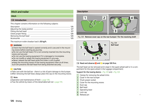 129
129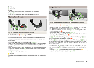 130
130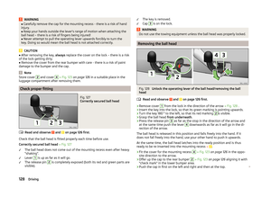 131
131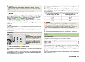 132
132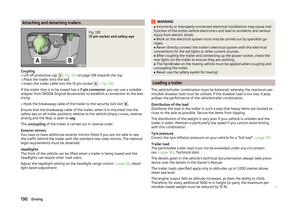 133
133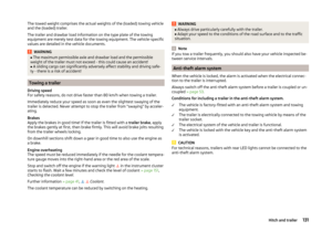 134
134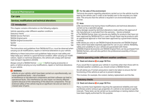 135
135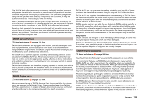 136
136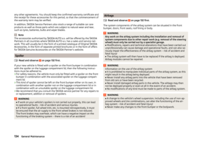 137
137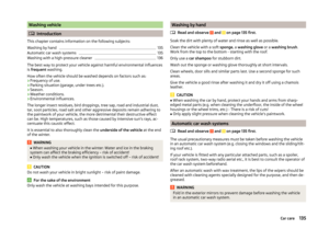 138
138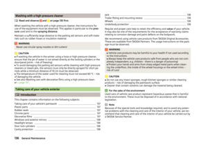 139
139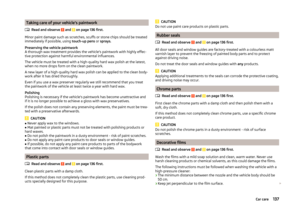 140
140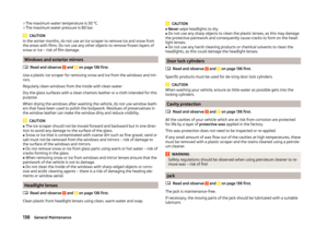 141
141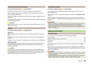 142
142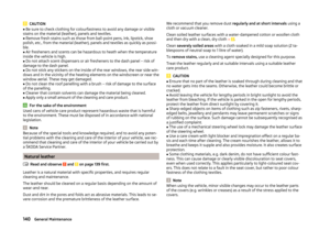 143
143 144
144 145
145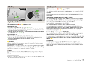 146
146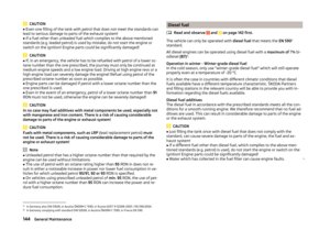 147
147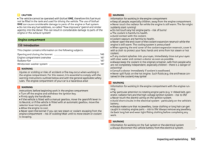 148
148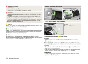 149
149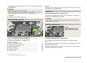 150
150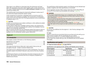 151
151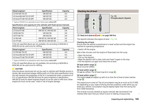 152
152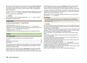 153
153 154
154 155
155 156
156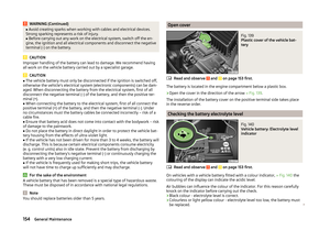 157
157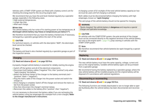 158
158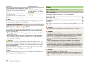 159
159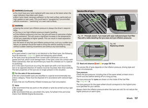 160
160 161
161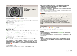 162
162 163
163 164
164 165
165 166
166 167
167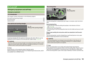 168
168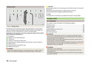 169
169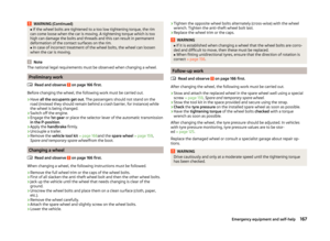 170
170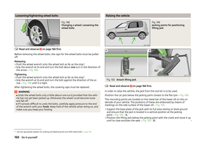 171
171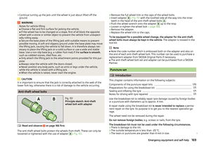 172
172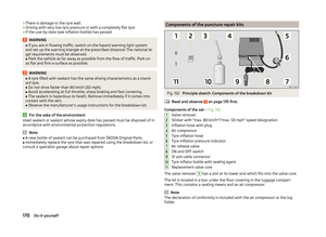 173
173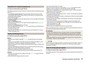 174
174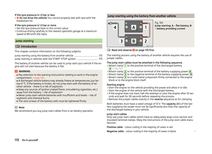 175
175 176
176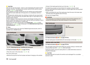 177
177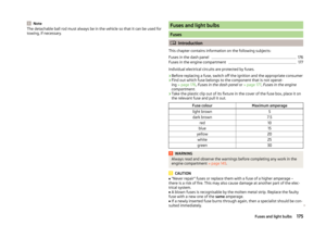 178
178 179
179 180
180 181
181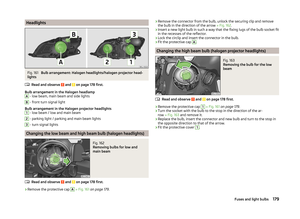 182
182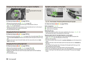 183
183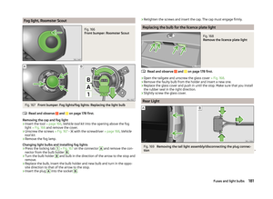 184
184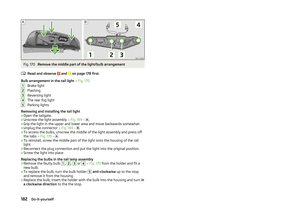 185
185 186
186 187
187 188
188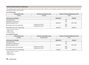 189
189 190
190 191
191 192
192 193
193 194
194 195
195 196
196 197
197 198
198 199
199 200
200 201
201 202
202 203
203