Page 169 of 200

CAUTIONThe detachable ball rod and/or the vehicle can be damaged if an unsuitable
tow bar is used.
Remote control
Introduction
This chapter contains information on the following subjects:
Replacing the battery in the remote control key
166
Synchronising the remote control
166
CAUTION
■ The replacement battery must have the same specification as the original
battery.■
We recommend having faulty rechargeable batteries replaced by a ŠKODA
service partner.
■
Pay attention to the correct polarity when changing the battery.
For the sake of the environment
Dispose of the used battery in accordance with national legal provisions.
Replacing the battery in the remote control key
Fig. 143
Remove cover/take out battery
Read and observe
on page 166 first.
The battery change is carried out as follows.
›
Flip out the key.
› Press off the battery cover A
» Fig. 143 with your thumb or using a flat
screwdriver in the region of the arrows 1.›
Remove the discharged battery from the key by pressing the battery down in
the region of the arrow
2
.
›
Insert the new battery.
›
Insert the battery cover
A
and press it down until it clicks audibly into place.
The key has to be synchronised if the vehicle cannot be unlocked or locked
with the remote control key after replacing the battery » page 166.
Note
If a key has an affixed decorative cover, this will be destroyed when the bat-
tery is replaced. A replacement cover can be purchased from a ŠKODA Partner.
Synchronising the remote control
Read and observe
on page 166 first.
If the vehicle does not unlock when pressing the remote control, the key may
not be synchronised. This can occur when the buttons on the remote control
key are actuated a number of times outside of the operative range of the
equipment or the battery in the remote control key has been replaced.
Synchronise the key as follows.
›
Press any button on the remote control key.
›
Unlock the door with the key in the lock cylinder within 1 minute of pressing the button.
Emergency unlocking/locking
Introduction
This chapter contains information on the following subjects:
Locking the door without a locking cylinder
167
Unlocking the tailgate
167
Selector lever-emergency unlocking
167166Do-it-yourself
Page 170 of 200

Locking the door without a locking cylinderFig. 144
Emergency locking: Left/right rear door
An emergency locking mechanism is located on the face side of the doors
which have no locking cylinder, it is only visible after opening the door.
›
Remove the cover
A
» Fig. 144 .
›
Insert the vehicle key into the slot and turn in the direction of the arrow
(sprung position).
›
Replace the cover
A
.
Unlocking the tailgate
Fig. 145
Emergency unlocking of the boot
lid
The boot lid can be unlocked manually in an emergency.
›
Insert the vehicle key into the slot in the trim panel » Fig. 145 as far as it will
go.
›
Unlock the lid by moving it in the direction of the arrow.
›
Open the boot lid.
Selector lever-emergency unlockingFig. 146
Selector lever-emergency unlocking
›
Firmly apply the handbrake.
›
With one hand on the edge of the cover, push in direction of arrow
1
» Fig. 146 .
›
At the same time lift the cover on the selector lever gaiter with the other
hand in direction of arrow
2
.
›
With one finger, push the yellow plastic element in the direction of arrow
3
down to the stop.
›
At the same time, press the locking button in the selector lever and movethe selector lever to position N.
If the selector lever is moved again to position P, it is once again blocked.
Replacing windscreen wiper blades
Introduction
This chapter contains information on the following subjects:
Replacing the windscreen wiper blades
168
Replacing the rear window wiper blade
168WARNINGReplace the windscreen wiper blades once or twice a year for safety rea-
sons. These can be purchased from a ŠKODA Partner.167Emergency equipment and self-help
Page 171 of 200

Replacing the windscreen wiper bladesFig. 147
Windscreen wiper blade
Read and observe
on page 167 first.
Before replacing the windscreen wiper blade, put the windscreen wiper arms
into the service position.
Service position for changing wiper blades
›
Closing the bonnet.
›
Switch the ignition on and off again.
›
Place the operating lever in position
4
» page 66 , Activating the windscreen
wipers and washers .
The windscreen wiper arms move into the service position.
Removing the wiper blade
›
Lift the wiper arm from the window in the direction of
1
» Fig. 147 .
›
Tilt the wiper blade to the stop in the same direction.
›
Hold the upper part of the wiper arm and press the securing mechanism
A
in the direction of arrow
2
.
›
Remove the wiper blade in the direction of the arrow
3
.
Attaching the windscreen wiper blade
›
Push the windscreen wiper blade to the stop until it locks into place.
›
Check that the windscreen wiper blade is correctly attached.
›
Fold the windscreen wiper arm back to the windscreen.
›
Turn on the ignition and press the lever into position
4
» page 66 , Activat-
ing the windscreen wipers and washers .
The windscreen wiper arms move into the home position.
Replacing the rear window wiper bladeFig. 148
Rear window wiper blade
Read and observe
on page 167 first.
Removing the wiper blade
›
Lift the wiper arm from the window in the direction of
1
» Fig. 148 .
›
Tilt the wiper blade to the stop in the same direction.
›
Hold the upper part of the wiper arm and press the securing mechanism
A
in the direction of arrow
2
.
›
Remove the wiper blade in the direction of the arrow
3
.
Attaching the windscreen wiper blade
›
Push the windscreen wiper blade to the stop until it locks into place.
›
Check that the windscreen wiper blade is correctly attached.
›
Fold the windscreen wiper arm back to the windscreen.
168Do-it-yourself
Page 172 of 200

Fuses and light bulbs
Fuses
Introduction
This chapter contains information on the following subjects:
Fuses in the dash panel
169
Assignment of the fuses in the dash panel
170
Fuses in the engine compartment
171
Fuse assignment in the engine compartment
171
Individual electrical circuits are protected by fuses.
Switch off the ignition and the corresponding power consuming device before
replacing a fuse.
Find out which fuse belongs to the component that is not operat-
ing » page 170 , Assignment of the fuses in the dash panel or » page 171 ,
Fuse assignment in the engine compartment .
Fuse colourMaximum amperagelight brown5dark brown7.5red10blue15yellow20white25green30orange40WARNINGAlways read and observe the warning notes before completing any work in
the engine compartment » page 137, Engine compartment .CAUTION■
“Never repair” fuses, and do not replace them with fuses of a higher amper-
age – risk of fire! This may also cause damage at other points in the electrical
system.■
A blown fuses is recognisable by the molten metal strip. Replace the faulty
fuse with a new one of the same amperage.
■
If a newly inserted fuse burns through again, then a specialist should be con-
sulted immediately.
Note
■ We recommend always carrying replacement fuses in the vehicle. A box of
replacement fuses can be purchased from ŠKODA Original Accessories.■
There can be several power consuming devices for one fuse.
■
Multiple fuses may exist for a single power consuming device.
Fuses in the dash panel
Fig. 149
Remove the fuse box cover.
Read and observe and on page 169 first.
The fuses are located on the bottom of the dash panel behind a cover.
Replacing fuses
›
Grip the fuse box cover at point
A
and take-out in the direction of ar-
row » Fig. 149 .
›
Remove the plastic clip from the holder in the fuse box cover in the dash
panel.
›
Place the clip on the respective fuse and pull this fuse out.
›
Insert a new fuse.
›
Replace the clamp in the original position.
›
Insert the top edge of the cover into the dash panel first.
Carefully push the cover in.
169Fuses and light bulbs
Page 173 of 200

Assignment of the fuses in the dash panelFig. 150
Schematic representation of the fuse box for vehicles with left-
hand steering/right-hand steering
Read and observe
and on page 169 first.
No.Power consumer1S-contact2START - STOP3Instrument cluster, headlight range adjustment, telephone, oil level
sensor, diagnostic port, dimmable interior rear-view mirror4Control unit for ABS/ESC, steering angle sensor strip with switches5Petrol engine: Speed regulating system6Reversing light (manual gearbox)7Ignition, engine control unit, automatic gearbox8Brake pedal switch, clutch switch, engine cooling fan9Operating controls for the heating, electronic control unit for air con-
ditioning system, park distance control, window lift, engine cooling
fan, heated washer nozzles10DC-DC converter11Mirror adjustment12Control unit for trailer detection13Electronic control unit for automatic gearbox, selector lever of the
automatic gearbox14Headlight range control15Not assignedNo.Power consumer16Power steering, speed sensor, engine control unit, control unit for
fuel pump17Daytime running lights/radio for vehicles with START-STOP18Mirror heater19Ignition lock input20Engine control unit, electronic control unit for fuel pump, fuel pump21Reversing lamp (automatic gearbox), fog lights with the function
CORNER
22
Operating controls for the heating, electronic control unit for air con-
ditioning system, telephone, instrument cluster, steering angle
sender, multi-function steering wheel, ignition key removal lock, di-
agnostic port, rain sensor23Interior lighting, storage compartment and luggage compartment,
side lights24Central control unit25Light switch26Rear window wiper27Operating lever underneath the steering wheel28Petrol engine: Purge valve, PTC heater29Injection, coolant pump30Fuel pump, ignition system, cruise control31Lambda probe32High-pressure fuel pump, control valve for fuel pressure33Engine control unit34Engine control unit, vacuum pump35Switch illumination, number plate light, parking light36High beam, light switch37Rear fog light, DC-DC converter38Fog lights39Air blower for heating40Not assigned41Heated front seats42Rear window heater 170Do-it-yourself
Page 174 of 200

No.Power consumer43Horn44Windscreen wipers45Boot lid lock, central locking system46Alarm47Cigarette lighter48ABS49Turn signal lights, brake lights50DC-DC converter, radio51Electric windows (driver's window and rear left window)52Electric windows (front passenger's window and rear right)53Windscreen washer54START-STOP instrument cluster, operating lever under the steering
wheel, multifunction steering wheel55Control unit for automatic gearbox56Headlight cleaning system57Headlights front, rear58Headlights front, rear
Fuses in the engine compartment
Fig. 151
Vehicle battery: Cover for the fuse box - variant 1 / variant 2
Read and observe and on page 169 first.
Replacing fuses
›
Press together the interlocks of the cover simultaneously in the direction of
the arrow
1
» Fig. 151 .
›
Remove the cover in the direction of the arrow
2
.
›
Replace the appropriate fuse.
›
Place the cover on top of the fuse box.
›
Push in the interlocks on the cover and lock.
The cover must engage securely.
Fuse assignment in the engine compartment
Fig. 152
Fuses
Read and observe and on page 169 first.
No.Power consumer1ABS2Radiator fan3Automatic gearbox4ABS5Central control unit6Electrical auxiliary heating system171Fuses and light bulbs
Page 175 of 200

173
Replacing bulb")
Replacing bulbs
Introduction
This chapter contains information on the following subjects:
Bulb arrangement in the headlights
172
Replacing the high beam bulb (halogen headlights)
173
Replacing bulb for main beam, daytime running lights and parking light
173
Changing the front turn signal bulb
174
Replacing the bulb for the fog light
174
Replacing the bulb for the licence plate light
175
Rear Light
175
Replacing bulbs in rear light
176
Some manual skills are required to change a bulb. For this reason, we recom-
mend having bulbs replaced by a specialist garage or seeking other expert help
in the event of any uncertainties.
› Switch off the ignition and all of the lights before replacing a bulb.
› Faulty bulbs must only be replaced with the same type of bulbs. The designa-
tion is located on the light socket or the glass bulb.
› A stowage compartment for replacement bulbs is located in a plastic box in
the spare wheel or underneath the floor covering in the boot.
WARNING■ Always read and observe the warning notes before completing any work
in the engine compartment » page 137.■
Accidents can be caused if the road in front of the vehicle is not suffi-
ciently illuminated and the vehicle cannot or can only be seen with difficul-
ty by other road users.
■
H7 and H15 bulbs are pressurised and may burst when changing the bulb -
risk of injury! We therefore recommended wearing gloves and safety
glasses when changing a bulb.
■
Gas discharge bulbs (xenon bulbs) operate with a high voltage, professio-
nal knowledge is required – risk of death!
■
Switch off the respective vehicle light when changing the bulb.
CAUTION
Do not take hold of the glass bulb with naked fingers (even the smallest
amount of dirt reduces the working life of the light bulb). Use a clean cloth,
napkin, or similar.Note■ This Owner's Manual only describes the replacement of bulbs where it is pos-
sible to replace the bulbs on your own without any complications arising. Other
bulbs must be replaced by a specialist garage.■
We recommend that a box of replacement bulbs always be carried in the ve-
hicle. Replacement bulbs can be purchased from ŠKODAOriginal Accessories.
■
We recommend having the headlight settings checked by a specialist garage
after replacing a bulb in the main, low or fog beam.
■
In case of failure of a xenon gas discharge lamp or an LED diode, visit a spe-
cialist garage.
Bulb arrangement in the headlights
Fig. 153
Principle sketch: Headlights
Read and observe and on page 172 first.
Bulb arrangement » Fig. 153
Low beam or low beam with xenon gas discharge lamp
Main beam, separate daytime running lights, and parking light
Turn signal light (at the front)
ABC172Do-it-yourself
Page 176 of 200
Fig. 154
Changing the bulb for the low beam
Read and observe
and on page 172 first.
›
Remove the protective cap
A
» Fig. 153 on page 172 .
�")
Replacing the high beam bulb (halogen headlights)Fig. 154
Changing the bulb for the low beam
Read and observe
and on page 172 first.
›
Remove the protective cap
A
» Fig. 153 on page 172 .
›
Remove the socket with the bulb by jiggling it out in the direction of arrow
1
» Fig. 154 .
›
Remove the connector.
›
Insert the connector with the new bulb in the direction of arrow
2
so that
the fixing lug
A
fits the bulb into the recess on the reflector.
›
Attach the connector.
›
Fit the protective cap
A
» Fig. 153 on page 172 .
Replacing bulb for main beam, daytime running lights and parking
light
Fig. 155
Replacing the bulb for main
beam and separate daytime run-
ning lights
Fig. 156
Change the light bulb for the parking light
Read and observe
and on page 172 first.
Removing/replacing the bulb for main beam and separate daytime running
lights
›
Remove the protective cap
B
» Fig. 153 on page 172 .
›
Pull the holder until it stops in the arrow direction
1
» Fig. 155 .
›
Remove the socket with the bulb in the direction of arrow
2
.
›
Change the bulb in the socket.
›
Insert the socket with the new bulb into the headlight in the opposite direc-
tion to the arrow
2
.
›
Turn the socket with the new bulb in the opposite direction to the arrow
1
until it stops.
›
Fit protective cap
B
» Fig. 153 on page 172 Insert.
Removing/replacing the bulb for the parking light
›
Remove the protective cap
B
» Fig. 153 on page 172 .
›
Remove the bulb holder with the bulb by jiggling it out in the direction of the
arrow
1
» Fig. 156 .
›
Grasp the lamp socket at the places marked by arrows.
›
Remove the faulty bulb from the holder in the direction of the arrow
2
.
›
Insert a new bulb in the bulb holder up to the stop.
›
Replace the bulb holder in the headlamp with the bulb.
›
Fit protective cap
B
» Fig. 153 on page 172 Insert.
173Fuses and light bulbs
 1
1 2
2 3
3 4
4 5
5 6
6 7
7 8
8 9
9 10
10 11
11 12
12 13
13 14
14 15
15 16
16 17
17 18
18 19
19 20
20 21
21 22
22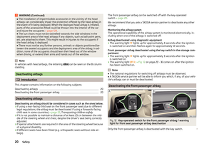 23
23 24
24 25
25 26
26 27
27 28
28 29
29 30
30 31
31 32
32 33
33 34
34 35
35 36
36 37
37 38
38 39
39 40
40 41
41 42
42 43
43 44
44 45
45 46
46 47
47 48
48 49
49 50
50 51
51 52
52 53
53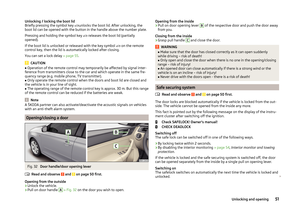 54
54 55
55 56
56 57
57 58
58 59
59 60
60 61
61 62
62 63
63 64
64 65
65 66
66 67
67 68
68 69
69 70
70 71
71 72
72 73
73 74
74 75
75 76
76 77
77 78
78 79
79 80
80 81
81 82
82 83
83 84
84 85
85 86
86 87
87 88
88 89
89 90
90 91
91 92
92 93
93 94
94 95
95 96
96 97
97 98
98 99
99 100
100 101
101 102
102 103
103 104
104 105
105 106
106 107
107 108
108 109
109 110
110 111
111 112
112 113
113 114
114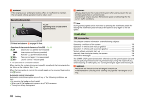 115
115 116
116 117
117 118
118 119
119 120
120 121
121 122
122 123
123 124
124 125
125 126
126 127
127 128
128 129
129 130
130 131
131 132
132 133
133 134
134 135
135 136
136 137
137 138
138 139
139 140
140 141
141 142
142 143
143 144
144 145
145 146
146 147
147 148
148 149
149 150
150 151
151 152
152 153
153 154
154 155
155 156
156 157
157 158
158 159
159 160
160 161
161 162
162 163
163 164
164 165
165 166
166 167
167 168
168 169
169 170
170 171
171 172
172 173
173 174
174 175
175 176
176 177
177 178
178 179
179 180
180 181
181 182
182 183
183 184
184 185
185 186
186 187
187 188
188 189
189 190
190 191
191 192
192 193
193 194
194 195
195 196
196 197
197 198
198 199
199