Page 153 of 200

Attention to the following notes may affect tyre wear.
Driving style
Fast cornering, sharp acceleration and braking increase the wear of your tyres.
Wheel balance
The wheels of a new vehicle are balanced. When driving, however, there are a
range of factors that may result in an imbalance. This may become apparent by
a “vibration” in the steering. If this is the case, have the wheels checked by a
specialist garage.
Have the wheels likewise rebalanced after replacing the tyres.
Setting the vehicle geometry
Incorrect wheel alignment at the front or rear leads to excess wear on the
tyres and impairs driving safety. With a distinctive tyre wear, we recommend
that you check the setting of the vehicle geometry in a specialist workshop.WARNING■ An incorrect wheel alignment at the front or rear impairs handling.■Unusual vibrations or pulling of the vehicle to one side could be a sign of
tyre damage. If there is any doubt that a wheel is damaged, immediately re-
duce your speed and stop! If no external tyre damage is evident, drive slow-
ly and carefully to the nearest specialist garage to have the vehicle
checked.
Tyre wear indicator and wheels exchange
Fig. 126
Principle sketch: Replace tire tread with wear indicators / wheels
Read and observe on page 148 first.
Wear indicators
The base of the tread of the tyres contains has a 1.6 mm high wear indica-
tor » Fig. 126 -
. In some countries, different tyre wear rates may apply.
Markings on the walls of the tyres through the letters “TWI”, triangular sym-
bols or other symbols identify the position of the wear indicators.
Exchanging the wheels
For uniform wear on all tyres, we recommend that you change the wheels ev-
ery 10 000 km according to the scheme » Fig. 126-
. You will then obtain ap-
proximately the same life for all the tyres.
After a wheel has been replaced, the tyre pressure has to be adjusted.
In vehicles with tyre pressure monitoring, tyre pressure values are to be stor-
ed » page 115 .
WARNING■
You must have your tyres replaced with new ones at the latest when the
wear indicators have been worn down.■
Worn tyres impair necessary adhesion to the road surface, particularly at
high speeds on wet roads. This could lead to “aquaplaning” (uncontrolled vehicle movement – “swimming” on a wet road surface).
Tyre damage
Read and observe
on page 148 first.
We recommend checking your tyres and wheel rims for damage (punctures,
cuts, splits and bulges, etc.) on a regular basis. Remove foreign bodies (e.g.
small stones) from the tyre tread immediately.
Drive over kerbs and other such obstacles slowly and at right angles wherever
possible in order to avoid damage to tyres and wheel trims.
Immediately replace damaged wheel rims or tyres.
WARNINGNever drive with damaged tyres – there is the risk of an accident occurring. 150General Maintenance
Page 154 of 200

CAUTIONThe tyres must be protected from contact with substances such as oil, grease
and fuel, which could damage them. If the tyres come into contact with these
substances, then we recommend you have this checked out in a specialist
workshop.
Unidirectional tyres
Read and observe
on page 148 first.
The direction of rotation of the tyres is marked by arrows on the wall of the
tyre .
The indicated direction of rotation must be adhered to in order to ensure the
optimal characteristics of these tyres.
These characteristics mainly relate to the following: › Increased driving stability.
› Reduced risk of aquaplaning.
› Reduced tyre noise and tyre wear.
Manufacturer-approved tyre variants
Introduction
This chapter contains information on the following subjects:
Explanation of the tyre labelling
151
Rapid
152
Rapid Green Line
152
Rapid Green tec
152
Approved tyre variants are first to be selected for the model variant (e.g. Rapid
GreenLine), and then selected according to the engine size of your vehicle.
If the model variant of your vehicle cannot be found in the discrete module,
then the approved tyre variants are to be selected according to the engine size
of your vehicle in module » page 152, Rapid .
Only use radial tyres of the same type, size (rolling circumference) and tread pattern on one axle on all four wheels.
When mounting new tyres the tyres have to be replaced axle by axle.
The information listed in the table corresponds to the information available at the time of going to press.
The approved tyre / rim combinations for your car are given on the sales and
technical vehicle documentation.
Explanation of the tyre labelling
Explanation of tyre markings
For example, 225/50R 17 91 T means:
225Tyre width in mm50Height/width ratio in %RCode letter for the type of tyre – Radial17Diameter of wheel in inches91Load indexTSpeed symbol
The date of manufacture is stated on the tyre wall (possibly on the inside).
For example DOT ... 11 14... means, for example, that the tyre was manufac-
tured in the 11th week of 2014.
The marking M+Smeans that the associated tyre is suitable for winter use.
Load index
The load index indicates the maximum permissible load for each individual
tyre.
Load index838485868788Load
(In kg)487500515530545560
Speed symbol
The maximum speed symbol indicates the maximum permissible vehicle speed
with fitted tyres in each category.
Speed
symbolSTUHVWMaximum speed
(in km/h)180190200210240270
151Wheels
Page 155 of 200

WARNING■Never exceed the maximum permissible load bearing capacity of moun-
ted tyres.■
Never exceed the maximum permissible speed for the mounted tyres.
CAUTION
The information about load index and speed symbol can be found in the vehi-
cle sales and technical documentation.
Rapid
MotorisationTyre sizeMinimal
Load indexMinimal
Speed symbol
1.2 l./55 kW MPI
175/70 R1484T185/60 R1584T215/45 R16 a)86T215/40 R17a)87T
1.2 l/63 kW TSI
175/70 R1484T185/60 R1584T215/45 R16 a)86T215/40 R17a)87T
1.2 l/77 kW TSI
185/60 R1584H195/55 R1585H215/45 R16 a)86H215/40 R17a)87H
1.4 l/90 kW TSI
185/60 R1584H195/55 R1585H215/45 R16 a)86H215/40 R17a)87H
1.6 l./77 kW MPI
185/60 R1584H195/55 R1585H215/45 R16 a)86H215/40 R17a)87HMotorisationTyre
sizeMinimal
Load indexMinimal
Speed symbol
1.6 l/66 kW TDI CR
185/60 R1584H195/55 R1585H215/45 R16 a)86H215/40 R17a)87H
1.6 l/77 kW TDI CR
185/60 R1584H195/55 R1585H215/45 R16 a)86H215/40 R17a)87Ha)
Not valid for the following markets: Armenia, Azerbaijan, Belarus, Georgia, Kazakhstan, Kyrgyzstan, Mol-
dova, Russia, Tajikistan, Turkmenistan, Ukraine, and Uzbekistan.
Rapid Green Line
MotorisationTyre
sizeMinimal
Load indexMinimal
Speed symbol1.6 l/66 kW TDI CR185/60 R1584H
Rapid Green tec
Applies only to vehicles with factory installed 15-inch wheels.
MotorisationTyre sizeMinimal
Load indexMinimal
Speed symbol1.2 l/77 kW TSI185/60 R1584H1.4 l/90 kW TSI185/60 R1584H1.6 l/66 kW TDI CR185/60 R1584H1.6 l/77 kW TDI CR185/60 R1584H
Winter operation
Introduction
This chapter contains information on the following subjects:
Winter tyres
153
Snow chains
153152General Maintenance
Page 156 of 200

Winter tyres
Summer tyres have less grip on ice, snow and at temperatures below 7 °C. This
is especially true of vehicles fitted with wide tyres or high-speed tyres .
Fitting winter tyres will significantly improve the handling of your vehicle when
driving in wintry road conditions.
To get best possible handling, winter tyres must be fitted to all four wheels. The minimum tread depth must be 4 mm.
Winter tyres (marked with M+S and a peak/snowflake symbol) of a lower speed
category can be used provided that the permissible maximum speed of these
tyres is not exceeded even if the possible maximum speed of the vehicle is
higher.
The speed limit for winter tyres can be set in the MAXI DOT display in the
menu item Winter tyres » page 47 .
Only use those tyres or wheel rims which have been approved by ŠKODA for
your model of vehicle.
For the sake of the environment
Fit the summer tyres on again in good time as they provide better handling
properties, a shorter braking distance, less tyre noise, and reduced tyre wear
on roads which are free of snow and ice as well as at temperatures above 7 °C.
The fuel consumption is also lower.
Snow chains
When driving in wintry road conditions, snow chains improve not only traction,
but also the braking performance.
Snow chains must only be mounted on the front wheels.
For technical reasons, it is only permissible to fit snow chains with the follow-
ing wheel/tyre combinations.
Wheel sizeDepth DTyre size5J x 14 a)35 mm175/70 R146J x 15 b)38 mm185/60 R156J x 15b)38 mm195/55 R15a)
Only fit snow chains with links and locks not larger than
9 mm.
b)
Only fit snow chains with links and locks not larger than 13 mm.
Remove the full wheel trims before installing the snow chains » page 157.WARNINGObserve the national legal regulations relating to the use of snow chains.
CAUTION
The chains are to be removed when driving on snow-free paths. They would
otherwise cause loss of performance and damage the tyres.153Wheels
Page 157 of 200

Do-it-yourself
Emergency equipment and self-help
Emergency equipment
Introduction
This chapter contains information on the following subjects:
Placement of the first-aid kit and warning triangle
154
Placement of the reflective vest
154
fire extinguisher
154
Vehicle tool kit
155
Placement of the first-aid kit and warning triangle
Fig. 127
First-aid kit/warning triangle
The following information is for the first aid kit and warning triangle from the
ŠKODA Original accessories valid.
For another first aid kit and warning triangle the storage compartments may
possibly be too small.
First-aid box
The first-aid box can be attached by a strap to the right-hand side of the
boot » Fig. 127 .
Warning triangle
The warning triangle can be attached to the rear wall trim panel with rubber
straps » Fig. 127 .
WARNINGThe first-aid kit and warning triangle must always be secured safely so that
they do not come loose when making an emergency braking or in a vehicle
collision which could cause injuries to occupants.
Note
■ Pay attention to the expiration date of the first-aid kit.■We recommend using a first-aid kit from ŠKODA Original Accessories, which
are available from a ŠKODA Partner.
Placement of the reflective vest
Fig. 128
Reflective vest
The reflective vest can be stored in a bracket under the driver's seat » Fig. 128.
fire extinguisher
Fig. 129
Fire extinguisher
The fire extinguisher is attached by two straps in a holder underneath the driv-
er's seat.
Removing/attaching
›
Loosen the two straps by pulling the buckles in the direction of the ar-
row » Fig. 129 .
154Do-it-yourself
Page 158 of 200

›Remove the fire extinguisher.›For mounting, fit the fire extinguisher back into the holder and secure it with
straps.
Please read carefully the instructions which are attached to the fire extin-
guisher.
The fire extinguisher must be checked by an authorised person once a year.
The national legal requirements must be observed.WARNINGThe fire extinguisher must always be secured safely so that they do not
come loose when making an emergency braking or in a vehicle collision
which could cause injuries to occupants.
Note
■ The fire extinguisher must comply with national legal requirements.■Pay attention to the expiration date of the fire extinguisher. Proper function-
ing of the fire extinguisher is not assured once it has passed its expiry date.■
The fire extinguisher is part of the scope of delivery in certain countries only.
Vehicle tool kit
Fig. 130
Vehicle tool kit
The vehicle tool kit is housed in a box in the spare wheel or in the storage
space for the spare wheel.
Depending on the equipment, not all the components listed in the on-board
tool kit have to be contained in it.
Screwdriver
Key for removing and installing the tail light
Adapter for anti-theft wheel bolts
Towing eye
Clamps for removing the wheel trims
Depending upon vehicle equipment: Jack with sign / puncture repair kit
Wheel wrench
Extraction pliers for wheel bolt caps
Replacement bulb setWARNINGThe factory-supplied lifting jack is only intended for your model of vehicle.
Under no circumstances attempt to lift heavier vehicles or other loads.
CAUTION
■ Screw the jack back into the starting position before storing in the box with
the tool kit.■
Ensure that the vehicle tool kit is safely secured in the boot.
■
Ensure that the box is always secured with the strap.
Note
The declaration of conformity is included with the jack or the log folder.
Reserve and temporary spare wheel
Introduction
This chapter contains information on the following subjects:
Remove / store wheel
156
Spare wheel
156
When using an emergency or spare wheel make sure to mount a wheel with
the appropriate dimensions and design as soon as possible.
After changing the spare wheel, the tyre pressure should be adjusted. In vehi- cles with tyre pressure monitoring, tyre pressure values are to be stor-
ed » page 115 .
123456789155Emergency equipment and self-help
Page 159 of 200

WARNING■If, in the case of puncture occurring, the spare tyre with a non-bound di-
rection or an opposite direction of rotation must be mounted, then drive
carefully. The best properties of the tyre are no longer present in this situa-
tion.■
If the dimensions or design of the spare wheel differ from the tyres fitted
to the vehicle (e.g. winter tyres or low-profile tyres), it must only be used
briefly in the event of a puncture and if an appropriately cautious style of
driving is adopted.
■
If the dimensions or design of the temporary spare wheel differ from the
fitted tyres, never drive faster than 80 km/h (or 50 mph).
■
Never use the temporary spare wheel if it is damaged.
Remove / store wheel
Fig. 131
Taking the wheel out
Read and observe on page 156 first.
The spare wheel is located in a well under the floor covering in the boot and is
fixed in place with a special bolt » Fig. 131.
Take out the wheel
›
Open the boot lid.
›
Lift up the floor in the luggage compartment.
›
Loosen the belt and take out the box with the tool kit.
›
Unscrew the nut in direction of arrow » Fig. 131.
›
Take out the wheel.
Stow the wheel
›
Place the wheel into the spare wheel well with the wheel rim pointing down-
ward.
›
Pull the fixing band through the opposite holes in the wheel rim.
› Screw on the nut in the opposite direction to the arrow
» Fig. 131 until the
wheel is safely secured.›
Place the box with the tool kit back into the spare wheel and secure it with
the tape.
›
Fold back the floor in the luggage compartment.
›
Close the boot lid.
Spare wheel
Read and observe
on page 156 first.
A warning label is displayed on the rim of the temporary spare wheel.
Please note the following if you intend to use the temporary spare wheel. › The warning label must not be covered after installing the wheel.
› Be particularly observant when driving.
› The temporary spare wheel is inflated to the maximum inflation pressure for
the vehicle » page 149.
› Only use this temporary spare wheel to reach the nearest specialist garage,
since it is not intended for permanent use.
WARNING■ Never drive with more than one temporary spare wheel mounted!■Only use the temporary spare wheel when absolutely necessary.■
Avoid accelerating at full throttle, sharp braking and fast cornering.
■
The snow chains cannot be used on the temporary spare wheel.
■
Observe the instructions on the warning sign of the temporary spare
wheel.
Changing a wheel
Introduction
This chapter contains information on the following subjects:
Preliminary work
157
Full wheel trim
157
Wheel bolts
157
Changing a wheel
158
Follow-up work
158
Loosening/tightening wheel bolts
158
156Do-it-yourself
Page 160 of 200

Raising the vehicle159Anti-theft wheel bolts160
For your own safety and the safety of the passengers, the following instruc-
tions must be observed before changing a wheel on the road.
Switch on the hazard warning lights system.
The warning triangle must be set up at the prescribed distance - observe
the national legal provisions when doing so.
Park the vehicle as far away as possible from the flow of traffic.
Choose a location with a flat, solid surface.
Have all the occupants get out. The passengers should not stand on the
road (instead they should remain behind a crash barrier, for instance) while
the wheel is being changed.
The following instructions must be followed if the vehicle is subsequently fit- ted with tyres or rims that differ from the factory-fitted ones » page 151, Ex-
planation of the tyre labelling .
The national legal requirements must be observed when changing a wheel.
Preliminary work
Before changing the wheel, the following work must be carried out.
›
Switch off the engine.
›
Engage the 1st gear or place the selector lever of the automatic transmission
in the P-position .
›
Firmly apply the handbrake.
›
Uncouple any trailers.
›
Remove the vehicle tool kit » page 155 and the spare wheel » page 155 from
the boot.
Full wheel trim
Before removing the wheel bolts, remove the wheel cover.
Extracting
›
Hook the clamp found in the vehicle tool kit » page 155 into the reinforced
edge of the wheel trim.
›
Push the wheel wrench through the clamp, support on the tyre and pull off
the wheel trim.
Installing›Press the wheel trim onto the wheel rim at the designated valve open-
ing » .
›
Then press the trim into the wheel rim until its entire circumference locks
correctly in place.
CAUTION
Notes from the factory or from the ŠKODA Original accessory delivered trim..■When using an anti-theft wheel bolt, make sure that this has been fitted ac-
cording to the position marked on the back of the wheel cover position.■
On the back of the wheel cover, the position for the anti-theft wheel bolt is
marked by means of a symbol. If the wheel cover is set outside the position
marked for the anti-theft wheel bolt, there is a risk of damaging the wheel
cover.
CAUTION
■ Use the pressure of your hand only, do not strike the full wheel trim. The
cover could be damaged.■
If wheel trims are fitted, an adequate flow of air must be assured in order to
cool the brake system.
Note
We recommend that you use wheel trims from ŠKODA Original Accessories.
Wheel bolts
Fig. 132
Remove the cap
Before removing the wheel bolts, remove the covering caps.
Extracting
›
Push the extraction pliers » page 155 sufficiently far onto the cap until the
inner catches of the pliers are positioned at the collar of the cap.
›
Remove the cap in the direction of the arrow » Fig. 132.
157Emergency equipment and self-help
 1
1 2
2 3
3 4
4 5
5 6
6 7
7 8
8 9
9 10
10 11
11 12
12 13
13 14
14 15
15 16
16 17
17 18
18 19
19 20
20 21
21 22
22 23
23 24
24 25
25 26
26 27
27 28
28 29
29 30
30 31
31 32
32 33
33 34
34 35
35 36
36 37
37 38
38 39
39 40
40 41
41 42
42 43
43 44
44 45
45 46
46 47
47 48
48 49
49 50
50 51
51 52
52 53
53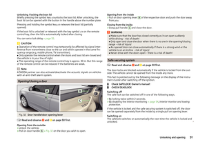 54
54 55
55 56
56 57
57 58
58 59
59 60
60 61
61 62
62 63
63 64
64 65
65 66
66 67
67 68
68 69
69 70
70 71
71 72
72 73
73 74
74 75
75 76
76 77
77 78
78 79
79 80
80 81
81 82
82 83
83 84
84 85
85 86
86 87
87 88
88 89
89 90
90 91
91 92
92 93
93 94
94 95
95 96
96 97
97 98
98 99
99 100
100 101
101 102
102 103
103 104
104 105
105 106
106 107
107 108
108 109
109 110
110 111
111 112
112 113
113 114
114 115
115 116
116 117
117 118
118 119
119 120
120 121
121 122
122 123
123 124
124 125
125 126
126 127
127 128
128 129
129 130
130 131
131 132
132 133
133 134
134 135
135 136
136 137
137 138
138 139
139 140
140 141
141 142
142 143
143 144
144 145
145 146
146 147
147 148
148 149
149 150
150 151
151 152
152 153
153 154
154 155
155 156
156 157
157 158
158 159
159 160
160 161
161 162
162 163
163 164
164 165
165 166
166 167
167 168
168 169
169 170
170 171
171 172
172 173
173 174
174 175
175 176
176 177
177 178
178 179
179 180
180 181
181 182
182 183
183 184
184 185
185 186
186 187
187 188
188 189
189 190
190 191
191 192
192 193
193 194
194 195
195 196
196 197
197 198
198 199
199