Page 81 of 181

PETROL INJECTION
Fault finding – Interpretation of faults17B
17B - 81V12 MR-372-J84-17B000$405.mif
SAGEM 3000
Program No.: A7
Vdiag No.: 44, 48PETROL INJECTION
Fault finding – Interpretation of faults
DF398
PRESENT
OR
STOREDFUEL CIRCUIT OPERATING FAULT
1.DEF : petrol circuit fault
NOTESPriority for dealing with a combination of faults:
Apply the procedure for dealing with faults DF081 Solenoid valve canister bleed and
DF085 Fuel pump relay first if they are present or stored.
Conditions for applying the fault finding procedure to stored faults:
The fault is declared present after an attempt is made to start the engine.
Special note:
–OBD warning light comes on.
Check the cleanliness, condition and fitting of the fuel vapour absorber.
Repair if necessary.
If the fault is still present, adjust the harness so that the fault status changes (present stored).
Look for any damage to the wiring harness, and check the condition and connection of the injection computer
and fuel vapour absorber connectors.
Repair if necessary.
If the fault is still present, check for the +12V on track 1 of the fuel vapour absorber.
If the +12V is not present, check the following connection for insulation, continuity and the absence of
interference resistance:
Fuel vapour absorber track 1 track 2 of connector PPM1 on the Protection and Switching Unit
Repair if necessary.
If the fault is still present, disconnect the battery and the injection computer.
Check the insulation, continuity and the absence of interference resistance on the following connection:
Computer, connectorC, track E1petrol vapour absorber track 2
Repair if necessary.
If the fault is still present, measure the resistance between tracks 1 and 2 of the fuel vapour absorber bleed
solenoid valve.
Replace the bleed solenoid valve for the fuel vapour absorber if the resistance is not 26 ±4 at 23 °C.
If the fault is still present, check the insulation, continuity and the absence of interference resistance on the
following connections:
Computer, connectorC, track D1 track 1 of the PEM connector of the Protection
and Switching Unit
Repair if necessary.
If the fault is still present, deal with the other faults, then proceed to the conformity check.
AFTER REPAIRFollow the instructions to confirm repair.
Deal with any other faults.
Clear the stored faults.
S3000_V44_DF398/S3000_V48_DF398JSAA741.0
MR-372-J84-17B000$405.mif
Page 82 of 181
PETROL INJECTION
Fault finding – Interpretation of faults17B
17B - 82V12 MR-372-J84-17B000$405.mif
SAGEM 3000
Program No.: A7
Vdiag No.: 44, 48
DF455
PRESENT
OR
STOREDLOW FUEL LEVEL SIGNAL
1.DEF : open circuit or short circuit
NOTESConditions for applying the fault finding procedure to stored faults:
The fault is declared present after an attempt is made to start the engine.
Run a multiplex network test (see 88B, Multiplex).
If the fault is still present, carry out fault finding on the Instrument panel system (see83A, Instrument panel).
AFTER REPAIRFollow the instructions to confirm repair.
Deal with any other faults.
Clear the stored faults.
JSAA741.0
Page 83 of 181

PETROL INJECTION
Fault finding – Interpretation of faults17B
17B - 83V12 MR-372-J84-17B000$405.mif
SAGEM 3000
Program No.: A7
Vdiag No.: 44, 48
DF608
PRESENT
OR
STOREDCLUTCH PEDAL SWITCH
1.DEF : signal incoherence
NOTESConditions for applying the fault finding procedure to stored faults:
The fault is declared present with the engine running and a road speed above 36 mph
(60 km/h).
Special note:
The acquisition is made if the vehicle is not fitted with an automatic transmission.
Check the cleanliness, condition and assembly of the clutch pedal switch and its connections.
Repair if necessary.
If the fault is still present, disconnect the switch. Check that when the clutch pedal is depressed, the switch is active,
and that when the clutch pedal is released, that the switch is not active and that the recommendations regarding
clutch pedal clearance are still valid (see MR 364, Mechanics,20A, Clutch
Replace the switch if necessary.
If the fault is still present, manipulate the harness so that the status changes (present stored).
Look for any damage to the wiring harness, and check the condition and connection of the injection computer
and clutch pedal switch connectors.
Repair if necessary.
If the fault is still present, check the earth on track 2 of the switch.
If there is no earth on track 2, check the insulation, continuity and the absence of interference resistance on
the following connection:
Clutch pedal switch track 2 earth
Repair if necessary.
If the fault is still present, check the insulation, continuity and the absence of interference resistance on the
following connections:
Clutch pedal switch track 1 Track C4, connector A, of the computer
Repair if necessary.
If the fault is still present, deal with the other faults, then proceed to the conformity check.
AFTER REPAIRFollow the instructions to confirm repair.
Deal with any other faults.
Clear the stored faults.
JSAA741.0
Page 84 of 181

PETROL INJECTION
Fault finding – Interpretation of faults17B
17B - 84V12 MR-372-J84-17B000$405.mif
SAGEM 3000
Program No.: A7
Vdiag No.: 44, 48
DF612
PRESENT
OR
STOREDOIL VAPOUR DEFREEZE RESISTOR CIRCUIT
CO.0 : open circuit or short circuit to earth
NOTESPriority for dealing with a combination of faults:
If the faults DF002 Air temperature sensor circuit, DF004 Turbocharging pressure
circuit, DF009 Gang 2 pedal potentiometer circuit or DF046 Battery voltage are
present, handle them first.
Conditions for applying the fault finding procedure to stored faults:
The fault appears after the ignition has been switched on.
Check the cleanliness and condition of the oil vapour defreeze resistor relay connections.
Clean or replace as necessary.
Measure the resistance of the defreeze resistor relay between tracks 1 and 2.
Replace the relay if the resistance is not:21at - 40 °C
9.5at 20 °C
13.4at 120 °C
With the ignition on, check for + 12 V on track 1 of the defreeze resistor relay.
Repair if necessary.
Disconnect the battery.
Disconnect the computer. Check the cleanliness and condition of the connections.
Using the Universal bornier, check the insulation, continuity and the absence of interference resistance for
the following connection:
Computer, connector B, track L2 track 2 of the oil vapour defreeze relay
Repair if necessary.
If the fault is still present, deal with the other faults, then proceed to the conformity check.
AFTER REPAIRFollow the instructions to confirm repair.
Deal with any other faults.
Clear the stored faults.
JSAA741.0
Page 85 of 181

PETROL INJECTION
Fault finding – Interpretation of faults17B
17B - 85V12 MR-372-J84-17B000$405.mif
SAGEM 3000
Program No.: A7
Vdiag No.: 44, 48
DF635
PRESENT
OR
STOREDLPG CYLINDER 1 COMBUSTION MISFIRE
1 DEF: Destructive misfire
2 DEF: Pollutant misfire
3 DEF: Non-compliance with emission control standards
NOTESPriority when dealing with a number of faults:
– LPG fuel system: see 17C, LPG injection,
– ignition:
DF072 Cylinder 1 ignition coil circuit
DF073 Cylinder 2 ignition coil circuit
DF074 Cylinder 3 ignition coil circuit
DF075 Cylinder 4 ignition coil circuit
– flywheel signal:
DF154 Flywheel signal sensor circuit
DF125 "Torque sensor programming"
Check whether there are other cylinders with an LPG combustion misfire fault detected
by the tool before starting the following fault finding procedure.
Conditions for applying the fault finding procedure to stored faults:
The fault appears under the following conditions:
– there must be no further electrical faults,
– the programming must have been done, particularly the flywheel target,
– warm engine (minimum 75 °C),
– run the engine at idle speed with all electrical consumers switched on for
approximately 15 minutes.
Special note:
– catalytic converter misfire: OBD warning light flashes when the fault is present then
is continuously lit,
– pollutant combustion misfire: OBD warning light lit continuously.
– engine unstable, loss of power and vibrations.
Misfiring on
cylinder 1 only
The fault is probably due to a component that can only affect this cylinder:
– check the cylinder 1 pencil coil,
– check the condition and conformity of the spark plugs,
– check the cylinder 1 LPG injector
If everything is in order, check the same components on cylinder 4 (to cover a possible
cylinder recognition error).
The fault is probably due to a component that affects a pair of cylinders:
– check the ignition coil circuit concerned (apply interpretation of fault
DF072 Cylinder 1 ignition coil circuit
DF073 Cylinder 2 ignition coil circuit
DF074 Cylinder 3 ignition coil circuit
DF075 Cylinder 4 ignition coil circuit
– check the condition and conformity of the spark plugs.
Combustion
misfires on
cylinders 1 and 4
AFTER REPAIRFollow the instructions to confirm repair.
Deal with any other faults.
Clear the stored faults.
Page 86 of 181

PETROL INJECTION
Fault finding – Interpretation of faults17B
17B - 86V12 MR-372-J84-17B000$405.mif
SAGEM 3000
Program No.: A7
Vdiag No.: 44, 48
DF636
PRESENT
OR
STOREDLPG CYLINDER 2 COMBUSTION MISFIRE
1 DEF: Destructive misfire
2 DEF: Pollutant misfire
3 DEF: Non-compliance with emission control standards
NOTESPriority when dealing with a number of faults:
– LPG fuel system: see 17C, LPG injection,
– ignition:
DF072 Cylinder 1 ignition coil circuit
DF073 Cylinder 2 ignition coil circuit
DF074 Cylinder 3 ignition coil circuit
DF075 Cylinder 4 ignition coil circuit
– flywheel signal:
DF154 Flywheel signal sensor circuit
DF125 "Torque sensor programming"
Check whether there are other cylinders with an LPG combustion misfire fault detected
by the tool before starting the following fault finding procedure.
Conditions for applying the fault finding procedure to stored faults:
The fault appears under the following conditions:
– there must be no further electrical faults,
– the programming must have been done, particularly the flywheel target,
– warm engine (minimum 75 °C),
– run the engine at idle speed with all electrical consumers switched on for
approximately 15 minutes.
Special note:
– catalytic converter misfire: OBD warning light flashes when the fault is present then
is continuously lit,
– pollutant combustion misfire: OBD warning light lit continuously.
– engine unstable, loss of power and vibrations.
Misfiring on
cylinder 2 only
The fault is probably due to a component that can only affect this cylinder:
– check the cylinder 2 pencil coil,
– check the condition and conformity of the spark plugs,
– check the cylinder 2 LPG injector
If everything is in order, check the same components on cylinder 3 (to cover a possible
cylinder recognition error).
The fault is probably due to a component that affects a pair of cylinders:
– check the ignition coil circuit concerned (apply interpretation of fault
DF072 Cylinder 1 ignition coil circuit
DF073 Cylinder 2 ignition coil circuit
DF074 Cylinder 3 ignition coil circuit
DF075 Cylinder 4 ignition coil circuit
– check the condition and conformity of the spark plugs.
Combustion
misfires in
cylinders 2 and 3
AFTER REPAIRFollow the instructions to confirm repair.
Deal with any other faults.
Clear the stored faults.
Page 87 of 181

PETROL INJECTION
Fault finding – Interpretation of faults17B
17B - 87V12 MR-372-J84-17B000$405.mif
SAGEM 3000
Program No.: A7
Vdiag No.: 44, 48
DF637
PRESENT
OR
STOREDLPG CYLINDER 3 COMBUSTION MISFIRE
1 DEF: Destructive misfire
2 DEF: Pollutant misfire
3 DEF: Non-compliance with emission control standards
NOTESPriority when dealing with a number of faults:
– LPG fuel system: see 17C, LPG injection,
– ignition:
DF072 Cylinder 1 ignition coil circuit
DF073 Cylinder 2 ignition coil circuit
DF074 Cylinder 3 ignition coil circuit
DF075 Cylinder 4 ignition coil circuit
– flywheel signal:
DF154 Flywheel signal sensor circuit
DF125 "Torque sensor programming"
Check whether there are other cylinders with an LPG combustion misfire fault detected
by the tool before starting the following fault finding procedure.
Conditions for applying the fault finding procedure to stored faults:
The fault appears under the following conditions:
– there must be no further electrical faults,
– the programming must have been done, particularly the flywheel target,
– warm engine (minimum 75 °C),
– run the engine at idle speed with all electrical consumers switched on for
approximately 15 minutes.
Special note:
– catalytic converter misfire: OBD warning light flashes when the fault is present then
is continuously lit,
– pollutant combustion misfire: OBD warning light lit continuously.
– engine unstable, loss of power and vibrations.
Misfiring on
cylinder 3 only
The fault is probably due to a component that can only affect this cylinder:
check the cylinder 3 pencil coil,
check the condition and conformity of the spark plugs,
check the cylinder 3 LPG injector
If everything is in order, check the same components on cylinder 2 (to cover a possible
cylinder recognition error).
The fault is probably due to a component that affects a pair of cylinders:
– check the ignition coil circuit concerned (apply interpretation of fault
DF072 Cylinder 1 ignition coil circuit
DF073 Cylinder 2 ignition coil circuit
DF074 Cylinder 3 ignition coil circuit
DF075 Cylinder 4 ignition coil circuit
– check the condition and conformity of the spark plugs.
Combustion
misfires in
cylinders 2 and 3
AFTER REPAIRFollow the instructions to confirm repair.
Deal with any other faults.
Clear the stored faults.
Page 88 of 181

PETROL INJECTION
Fault finding – Interpretation of faults17B
17B - 88V12 MR-372-J84-17B000$405.mif
SAGEM 3000
Program No.: A7
Vdiag No.: 44, 48
DF638
PRESENT
OR
STOREDLPG CYLINDER 4 COMBUSTION MISFIRE
1 DEF: Destructive misfire
2 DEF: Pollutant misfire
3 DEF: Non-compliance with emission control standards
NOTESPriority when dealing with a number of faults:
– LPG fuel system: see 17C, LPG injection,
– ignition:
DF072 Cylinder 1 ignition coil circuit
DF073 Cylinder 2 ignition coil circuit
DF074 Cylinder 3 ignition coil circuit
DF075 Cylinder 4 ignition coil circuit
– flywheel signal:
DF154 Flywheel signal sensor circuit
DF125 "Torque sensor programming"
Check whether there are other cylinders with an LPG combustion misfire fault detected
by the tool before starting the following fault finding procedure.
Conditions for applying the fault finding procedure to stored faults:
The fault appears under the following conditions:
– there must be no further electrical faults,
– the programming must have been done, particularly the flywheel target,
– warm engine (minimum 75 °C),
– run the engine at idle speed with all electrical consumers switched on for
approximately 15 minutes.
Special note:
– catalytic converter misfire: OBD warning light flashes when the fault is present then
is continuously lit,
– pollutant combustion misfire: OBD warning light lit continuously.
– engine unstable, loss of power and vibrations.
Misfiring on
cylinder 4 only
The fault is probably due to a component that can only affect this cylinder:
– check the pencil coil of cylinder 4,
– check the condition and conformity of the spark plugs,
– check the cylinder 4 LPG injector
If everything is in order, check the same components on cylinder 1 (to cover a possible
cylinder recognition error).
The fault is probably due to a component that affects a pair of cylinders:
– check the ignition coil circuit concerned (apply interpretation of fault
DF072 Cylinder 1 ignition coil circuit
DF073 Cylinder 2 ignition coil circuit
DF074 Cylinder 3 ignition coil circuit
DF075 Cylinder 4 ignition coil circuit
– check the condition and conformity of the spark plugs.
Combustion
misfires on
cylinders 1 and 4
AFTER REPAIRFollow the instructions to confirm repair.
Deal with any other faults.
Clear the stored faults.
 1
1 2
2 3
3 4
4 5
5 6
6 7
7 8
8 9
9 10
10 11
11 12
12 13
13 14
14 15
15 16
16 17
17 18
18 19
19 20
20 21
21 22
22 23
23 24
24 25
25 26
26 27
27 28
28 29
29 30
30 31
31 32
32 33
33 34
34 35
35 36
36 37
37 38
38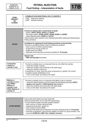 39
39 40
40 41
41 42
42 43
43 44
44 45
45 46
46 47
47 48
48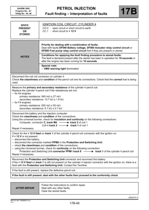 49
49 50
50 51
51 52
52 53
53 54
54 55
55 56
56 57
57 58
58 59
59 60
60 61
61 62
62 63
63 64
64 65
65 66
66 67
67 68
68 69
69 70
70 71
71 72
72 73
73 74
74 75
75 76
76 77
77 78
78 79
79 80
80 81
81 82
82 83
83 84
84 85
85 86
86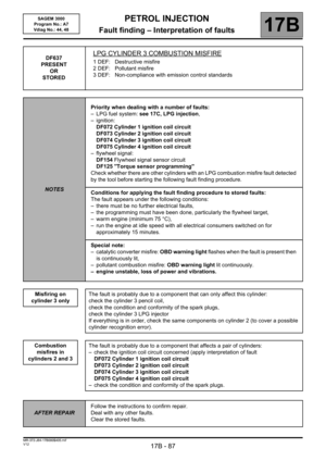 87
87 88
88 89
89 90
90 91
91 92
92 93
93 94
94 95
95 96
96 97
97 98
98 99
99 100
100 101
101 102
102 103
103 104
104 105
105 106
106 107
107 108
108 109
109 110
110 111
111 112
112 113
113 114
114 115
115 116
116 117
117 118
118 119
119 120
120 121
121 122
122 123
123 124
124 125
125 126
126 127
127 128
128 129
129 130
130 131
131 132
132 133
133 134
134 135
135 136
136 137
137 138
138 139
139 140
140 141
141 142
142 143
143 144
144 145
145 146
146 147
147 148
148 149
149 150
150 151
151 152
152 153
153 154
154 155
155 156
156 157
157 158
158 159
159 160
160 161
161 162
162 163
163 164
164 165
165 166
166 167
167 168
168 169
169 170
170 171
171 172
172 173
173 174
174 175
175 176
176 177
177 178
178 179
179 180
180