2014 RENAULT SCENIC fuel filter
[x] Cancel search: fuel filterPage 140 of 181

PETROL INJECTION
Fault finding – Interpretation of statuses17B
17B - 140V12 MR-372-J84-17B000$540.mif
SAGEM 3000
Program No.: A7
Vdiag No.: 44, 48
ET054
IDLING SPEED REGULATION
NOTESThere must be no present or stored faults.
Check the parameters PR032, PR058, PR064, PR118, PR119 and PR030.
Check that all these parameters are completely correct.
IDLING SPEED
TOO LOW
Check:
– the engine oil level (too high splashing),
– that the exhaust pipe is not blocked (catalytic converter damaged),
– the cleanliness and conformity of the air filter,
– that the air inlet circuit is not blocked,
– that the throttle valve is not clogged,
– the condition and conformity of the spark plugs,
– the fuel circuit sealing,
– the fuel pressure and flow (see MR 364 Mechanics, 17B, Petrol injection),
– the condition and cleanliness of the injectors,
– the cylinder compression's,
– the timing adjustment,
– the hydraulic tappets if there is camshaft noise (see MR 364 Mechanics, 11A, Top and front of engine).
Repair the defective component if necessary.
JSAA741.0
Page 143 of 181

PETROL INJECTION
Fault finding – Interpretation of statuses17B
17B - 143V12 MR-372-J84-17B000$540.mif
SAGEM 3000
Program No.: A7
Vdiag No.: 44, 48
ET055
CONTINUED
Check:
– the condition of the air filter,
– that the air inlet circuit is not blocked,
– the condition and conformity of the spark plugs,
– the sealing between the throttle valve and inlet manifold,
– the manifold pressure sensor sealing,
– the fuel vapour absorber bleed, which must not be jammed open,
– the fuel vapour absorber bleed system sealing,
– the brake servo system sealing,
– the turbocharger safety valve circuit sealing,
– the cylinder head oil vapour recovery system sealing,
– the sealing between the inlet manifold and cylinder head,
– the exhaust pipe sealing between the cylinder head and catalytic converter.
– the fuel flow rate and pressure.
If the idling speed is not stable, check:
– the timing adjustment,
– the hydraulic tappets if there is camshaft noise (seeMR 364 Mechanical, 11A, Top and front of engine),
– the cylinder compression's.
Drive the vehicle to check the repair.
Repair the defective components.
AFTER REPAIRRepeat the conformity check from the start.
JSAA741.0
Page 159 of 181

PETROL INJECTION
Fault finding – Interpretation of parameters17B
17B - 159V12 MR-372-J84-17B000$675.mif
SAGEM 3000
Program No.: A7
Vdiag No.: 44, 48
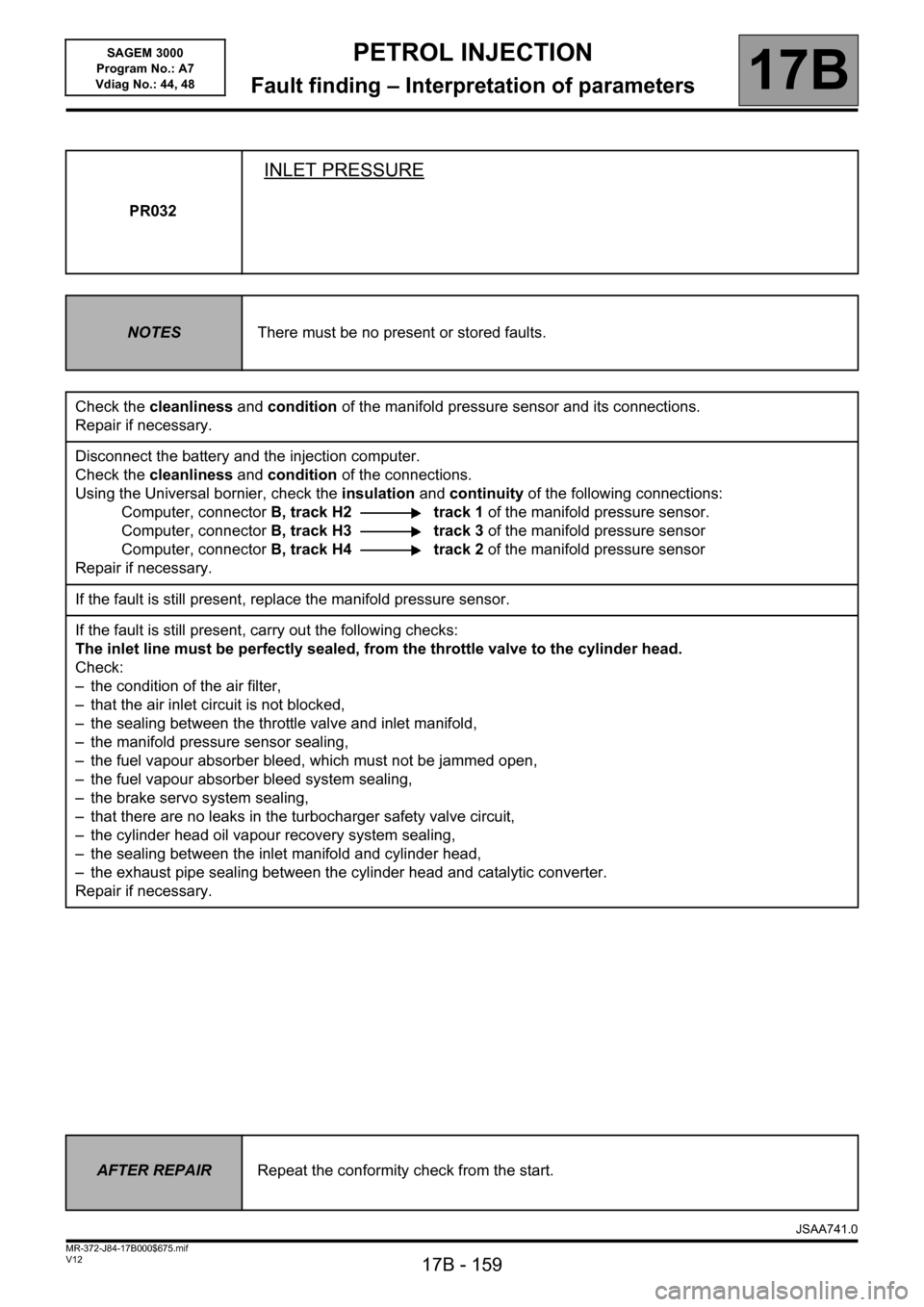
PR032
INLET PRESSURE
NOTESThere must be no present or stored faults.
Check the cleanliness and condition of the manifold pressure sensor and its connections.
Repair if necessary.
Disconnect the battery and the injection computer.
Check the cleanliness and condition of the connections.
Using the Universal bornier, check the insulation and continuity of the following connections:
Computer, connectorB, track H2 track 1 of the manifold pressure sensor.
Computer, connectorB, track H3 track 3 of the manifold pressure sensor
Computer, connectorB, track H4 track 2 of the manifold pressure sensor
Repair if necessary.
If the fault is still present, replace the manifold pressure sensor.
If the fault is still present, carry out the following checks:
The inlet line must be perfectly sealed, from the throttle valve to the cylinder head.
Check:
– the condition of the air filter,
– that the air inlet circuit is not blocked,
– the sealing between the throttle valve and inlet manifold,
– the manifold pressure sensor sealing,
– the fuel vapour absorber bleed, which must not be jammed open,
– the fuel vapour absorber bleed system sealing,
– the brake servo system sealing,
– that there are no leaks in the turbocharger safety valve circuit,
– the cylinder head oil vapour recovery system sealing,
– the sealing between the inlet manifold and cylinder head,
– the exhaust pipe sealing between the cylinder head and catalytic converter.
Repair if necessary.
AFTER REPAIRRepeat the conformity check from the start.
JSAA741.0
Page 163 of 181

PETROL INJECTION
Fault finding – Interpretation of parameters17B
17B - 163V12 MR-372-J84-17B000$675.mif
SAGEM 3000
Program No.: A7
Vdiag No.: 44, 48
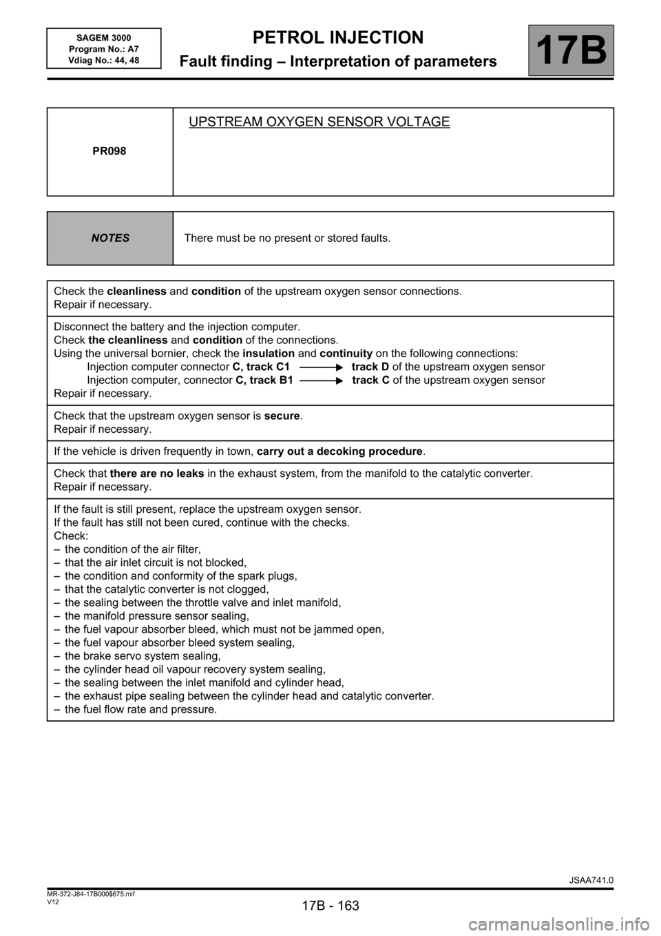
PR098
UPSTREAM OXYGEN SENSOR VOLTAGE
NOTESThere must be no present or stored faults.
Check the cleanliness and condition of the upstream oxygen sensor connections.
Repair if necessary.
Disconnect the battery and the injection computer.
Check the cleanliness and condition of the connections.
Using the universal bornier, check the insulation and continuity on the following connections:
Injection computer connectorC, track C1 track D of the upstream oxygen sensor
Injection computer, connectorC, track B1 track C of the upstream oxygen sensor
Repair if necessary.
Check that the upstream oxygen sensor is secure.
Repair if necessary.
If the vehicle is driven frequently in town, carry out a decoking procedure.
Check that there are no leaks in the exhaust system, from the manifold to the catalytic converter.
Repair if necessary.
If the fault is still present, replace the upstream oxygen sensor.
If the fault has still not been cured, continue with the checks.
Check:
– the condition of the air filter,
– that the air inlet circuit is not blocked,
– the condition and conformity of the spark plugs,
– that the catalytic converter is not clogged,
– the sealing between the throttle valve and inlet manifold,
– the manifold pressure sensor sealing,
– the fuel vapour absorber bleed, which must not be jammed open,
– the fuel vapour absorber bleed system sealing,
– the brake servo system sealing,
– the cylinder head oil vapour recovery system sealing,
– the sealing between the inlet manifold and cylinder head,
– the exhaust pipe sealing between the cylinder head and catalytic converter.
– the fuel flow rate and pressure.
JSAA741.0
Page 179 of 181

PETROL INJECTION
Fault finding – Fault Finding Chart17B
17B - 179V12 MR-372-J84-17B000$900.mif
SAGEM 3000
Program No.: A7
Vdiag No.: 44, 48
ALP 2 The engine will not start
NOTESFollow ALP 2 after a complete check with the diagnostic tool.
(Use the relevant section in the Workshop Repair Manual to carry out certain
operations).
WARNING
Never drive the vehicle without checking first that there are no throttle valve
faults.
If the starter motor does not operate, there may be a fault with the engine immobiliser.
Carry out a fault finding procedure on the UCH.
Check the condition of the battery.
Check the cleanliness, condition and tightness of the battery terminals.
Check that the battery is correctly earthed to the vehicle bodywork.
Check that the + battery leads are correctly connected.
Check that the starter motor is properly connected.
Check that the starter works (see MR 364 Mechanics, 16A, Starting-charging).
Check the condition and conformity of the spark plugs.
Check the mounting, cleanliness and condition of the flywheel signal sensor.
Check the flywheel signal sensor air gap.
Check the condition of the flywheel.
Check that the air filter is not clogged.
Check that the air inlet circuit is not blocked.
Check that there is fuel in the tank (fuel sender fault).
Check that the tank vent is not blocked.
Check that the fuel is of the correct type.
Check that there are no leaks in the fuel system, from the tank to the injectors.
Check that there are no kinked hoses (especially after a removal operation).
Check the fuel flow rate and pressure.
Check the sealing of the injectors, and that they are working properly.
Check that the exhaust system is not blocked and the catalytic converter not clogged.
Check the timing setting.
Check the cylinder compressions.
Check the hydraulic tappets if there is camshaft noise.
AFTER REPAIRRepeat the conformity check from the start.
JSAA741.0
Page 180 of 181

PETROL INJECTION
Fault finding – Fault Finding Chart17B
17B - 180V12 MR-372-J84-17B000$900.mif
SAGEM 3000
Program No.: A7
Vdiag No.: 44, 48
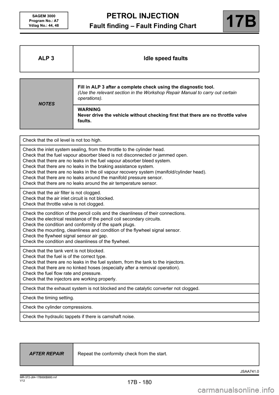
ALP 3 Idle speed faults
NOTESFill in ALP 3 after a complete check using the diagnostic tool.
(Use the relevant section in the Workshop Repair Manual to carry out certain
operations).
WARNING
Never drive the vehicle without checking first that there are no throttle valve
faults.
Check that the oil level is not too high.
Check the inlet system sealing, from the throttle to the cylinder head.
Check that the fuel vapour absorber bleed is not disconnected or jammed open.
Check that there are no leaks in the fuel vapour absorber bleed system.
Check that there are no leaks in the braking assistance system.
Check that there are no leaks in the oil vapour recovery system (manifold/cylinder head).
Check that there are no leaks around the manifold pressure sensor.
Check that there are no leaks around the air temperature sensor.
Check that the air filter is not clogged.
Check that the air inlet circuit is not blocked.
Check that throttle valve is not clogged.
Check the condition of the pencil coils and the cleanliness of their connections.
Check the electrical resistance of the pencil coil secondary circuits.
Check the condition and conformity of the spark plugs.
Check the mounting, cleanliness and condition of the flywheel signal sensor.
Check the flywheel signal sensor air gap.
Check the condition and cleanliness of the flywheel.
Check that the tank vent is not blocked.
Check that the fuel is of the correct type.
Check that there are no leaks in the fuel system, from the tank to the injectors.
Check that there are no kinked hoses (especially after a removal operation).
Check the fuel flow rate and pressure.
Check that the injectors are working properly.
Check that the exhaust system is not blocked and the catalytic converter not clogged.
Check the timing setting.
Check the cylinder compressions.
Check the hydraulic tappets if there is camshaft noise.
AFTER REPAIRRepeat the conformity check from the start.
JSAA741.0
Page 181 of 181

PETROL INJECTION
Fault finding – Fault Finding Chart17B
17B - 181V12 MR-372-J84-17B000$900.mif
SAGEM 3000
Program No.: A7
Vdiag No.: 44, 48
ALP 4 Faults occurring while driving
NOTESFill in ALP 4 after a complete check using the diagnostic tool.
(Use the relevant section in the Workshop Repair Manual to carry out certain
operations).
WARNING
Never drive the vehicle without checking first that there are no throttle valve
faults.
Check that the oil level is not too high.
Check the condition of the pencil coils and the cleanliness of their connections.
Check the electrical resistance of the pencil coil secondary circuits.
Check the condition and conformity of the spark plugs.
Check the mounting, cleanliness and condition of the flywheel signal sensor.
Check the flywheel signal sensor air gap.
Check the condition and cleanliness of the flywheel.
Check that the air filter is not clogged.
Check that the air inlet circuit is not blocked.
Check that throttle valve is not clogged.
Check the inlet system sealing, from the throttle to the cylinder head.
Check that the fuel vapour absorber bleed is not disconnected or jammed open.
Check that there are no leaks in the fuel vapour absorber bleed system.
Check that there are no leaks in the braking assistance system.
Check that there are no leaks in the oil vapour recovery system (manifold/cylinder head).
Check that there are no leaks around the manifold pressure sensor.
Check that there are no leaks around the air temperature sensor.
Check that the tank vent is not blocked.
Check that the fuel is of the correct type.
Check that there are no leaks in the fuel system, from the tank to the injectors.
Check that there are no kinked hoses (especially after a removal operation).
Check the fuel flow rate and pressure.
Check that the injectors are working properly.
Check that the exhaust system is not blocked and the catalytic converter not clogged.
Check the timing setting.
Check the cylinder compressions.
Check the hydraulic tappets if there is camshaft noise.
AFTER REPAIRRepeat the conformity check from the start.
JSAA741.0