2014 NISSAN TEANA SEC
[x] Cancel search: SECPage 3256 of 4801

MWI
MWI-1
DRIVER INFORMATION & MULTIMEDIA
C
D E
F
G H
I
J
K L
M B
SECTION MWI
A
O P
CONTENTS
METER, WARNING LAMP & INDICATOR
PRECAUTION ................ ...............................4
PRECAUTIONS .............................................. .....4
Precaution for Supplemental Restraint System
(SRS) "AIR BAG" and "SEAT BELT PRE-TEN-
SIONER" ............................................................. ......
4
PREPARATION ............................................5
PREPARATION .............................................. .....5
Special Service Tools .......................................... ......5
Commercial Service Tools ........................................5
SYSTEM DESCRIPTION ..............................6
COMPONENT PARTS ................................... .....6
METER SYSTEM .........................................................6
METER SYSTEM : Compo nent Parts Location ........6
METER SYSTEM : Component Description ....... ......7
SYSTEM ..............................................................9
METER SYSTEM .........................................................9
METER SYSTEM : System Diagram ........................9
METER SYSTEM : System Description ....................9
METER SYSTEM : Arrangem ent of Combination
Meter ................................................................... ....
10
METER SYSTEM : Fail-Safe ..................................10
SPEEDOMETER ................ ........................................11
SPEEDOMETER : System Diagram ................... ....11
SPEEDOMETER : System Description ...................11
TACHOMETER ...................................................... ....11
TACHOMETER : System Diagram .........................12
TACHOMETER : System De scription .....................12
ENGINE COOLANT TEMPERATURE GAUGE .... ....12
ENGINE COOLANT TEMPERATURE GAUGE :
System Diagram .................................................. ....
12
ENGINE COOLANT TEMPERATURE GAUGE :
System Description ............................................. ....
12
FUEL GAUGE ........................................................ ....12
FUEL GAUGE : System Diagram ............................12
FUEL GAUGE : System Description .......................12
MASTER WARNING LAMP ................................... ....12
MASTER WARNING LAMP : System Diagram .......13
MASTER WARNING LAMP : System Description ....13
METER ILLUMINATION CONTROL ..................... ....13
METER ILLUMINATION CONTROL : System Di-
agram .................................................................. ....
13
METER ILLUMINATION CONTROL : System De-
scription ............................................................... ....
13
METER EFFECT FUNCTION ................................ ....13
METER EFFECT FUNCTION : System Diagram ....14
METER EFFECT FUNCTION : System Descrip-
tion ....................................................................... ....
14
INFORMATION DISPLAY ...................................... ....15
INFORMATION DISPLAY : System Diagram ..........15
INFORMATION DISPLAY : System Description .....15
COMPASS ............................................................. ....16
COMPASS : Description ..........................................16
DIAGNOSIS SYSTEM (METER) .......................18
Description ........................................................... ....18
CONSULT Function (METER/M&A) ........................18
ECU DIAGNOSIS INFORMATION ..............22
COMBINATION METER ...................................22
Reference Value .................................................. ....22
Fail-Safe ..................................................................27
DTC Index ...............................................................27
BCM, IPDM E/R .................................................29
List of ECU Reference .............................................29
WIRING DIAGRAM ......................................30
COMPASS .........................................................30
Revision: November 20132014 Altima NAMRevision: November 20132014 Altima NAM
Page 3259 of 4801

MWI-4
< PRECAUTION >
PRECAUTIONS
PRECAUTION
PRECAUTIONS
Precaution for Supplemental Restraint System (SRS) "AIR BAG" and "SEAT BELT
PRE-TENSIONER"
INFOID:0000000009951603
The Supplemental Restraint System such as “A IR BAG” and “SEAT BELT PRE-TENSIONER”, used along
with a front seat belt, helps to reduce the risk or severi ty of injury to the driver and front passenger for certain
types of collision. Information necessary to service the system safely is included in the SR and SB section of
this Service Manual.
WARNING:
• To avoid rendering the SRS inopera tive, which could increase the risk of personal injury or death in
the event of a collision which would result in air bag inflation, all maintenance must be performed by
an authorized NISS AN/INFINITI dealer.
• Improper maintenance, including in correct removal and installation of the SRS, can lead to personal
injury caused by unintent ional activation of the system. For re moval of Spiral Cable and Air Bag
Module, see the SR section.
• Do not use electrical test equipmen t on any circuit related to the SRS unless instructed to in this
Service Manual. SRS wiring harn esses can be identified by yellow and/or orange harnesses or har-
ness connectors.
PRECAUTIONS WHEN USING POWER TOOLS (AIR OR ELECTRIC) AND HAMMERS
WARNING:
• When working near the Airbag Diagnosis Sensor Unit or other Airbag System sensors with the Igni-
tion ON or engine running, DO NOT use air or electri c power tools or strike near the sensor(s) with a
hammer. Heavy vibration could activate the sensor( s) and deploy the air bag(s), possibly causing
serious injury.
• When using air or electric power tools or hammers , always switch the Ignition OFF, disconnect the
battery and wait at least three minutes before performing any service.
Revision: November 20132014 Altima NAMRevision: November 20132014 Altima NAM
Page 3266 of 4801

MWI
SYSTEMMWI-11
< SYSTEM DESCRIPTION >
C
D E
F
G H
I
J
K L
M B
A
O P
SPEEDOMETER
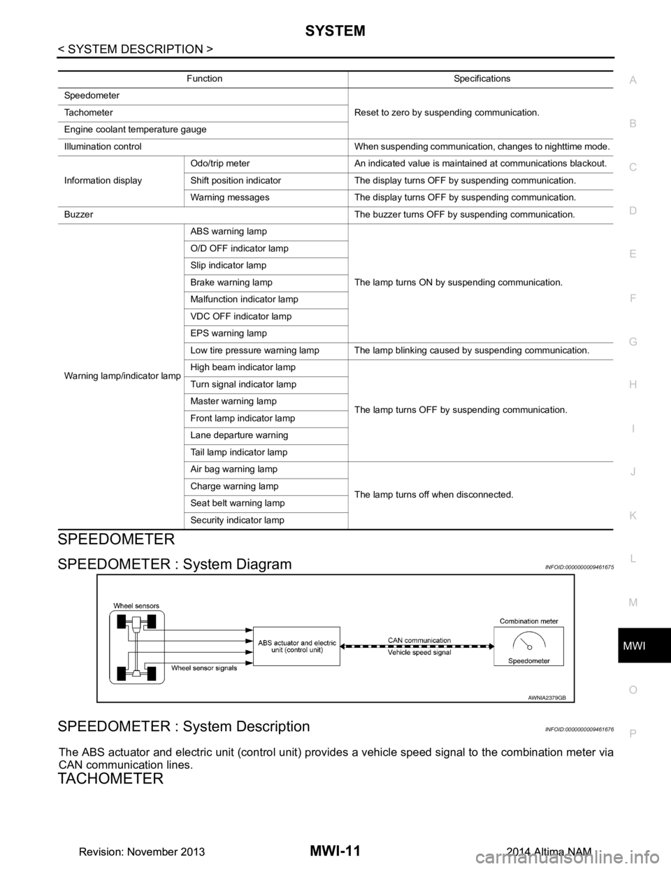
SPEEDOMETER : System DiagramINFOID:0000000009461675
SPEEDOMETER : System DescriptionINFOID:0000000009461676
The ABS actuator and electric unit (control unit) provi des a vehicle speed signal to the combination meter via
CAN communication lines.
TACHOMETER
Function Specifications
Speedometer Reset to zero by suspending communication.
Tachometer
Engine coolant temperature gauge
Illumination control When suspending communication, changes to nighttime mode.
Information display Odo/trip meter An indicated value is maintained at communications blackout.
Shift position indicator The display turns OFF by suspending communication.
Warning messages The display turns OFF by suspending communication.
Buzzer The buzzer turns OFF by suspending communication.
Warning lamp/indicator lamp ABS warning lamp
The lamp turns ON by suspending communication.
O/D OFF indicator lamp
Slip indicator lamp
Brake warning lamp
Malfunction indicator lamp
VDC OFF indicator lamp
EPS warning lamp
Low tire pressure warning lamp The lamp blinking caused by suspending communication.
High beam indicator lamp
The lamp turns OFF by suspending communication.
Turn signal indicator lamp
Master warning lamp
Front lamp indicator lamp
Lane departure warning
Tail lamp indicator lamp
Air bag warning lamp
The lamp turns off when disconnected.
Charge warning lamp
Seat belt warning lamp
Security indicator lamp
AWNIA2379GB
Revision: November 20132014 Altima NAMRevision: November 20132014 Altima NAM
Page 3272 of 4801

MWI
SYSTEMMWI-17
< SYSTEM DESCRIPTION >
C
D E
F
G H
I
J
K L
M B
A
O P
ZONE VARIATION SETTING PROCEDURE
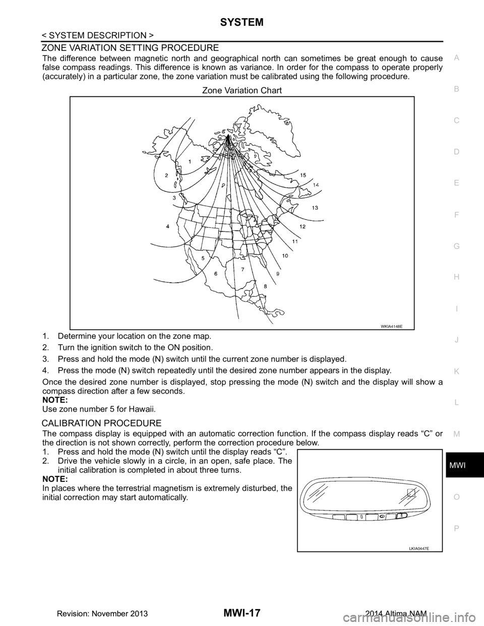
The difference between magnetic north and geographica l north can sometimes be great enough to cause
false compass readings. This difference is known as variance. In order for the compass to operate properly
(accurately) in a particular zone, the zone variat ion must be calibrated using the following procedure.
Zone Variation Chart
1. Determine your location on the zone map.
2. Turn the ignition switch to the ON position.
3. Press and hold the mode (N) switch until the current zone number is displayed.
4. Press the mode (N) switch repeatedly until the desired zone number appears in the display.
Once the desired zone number is displayed, stop pres sing the mode (N) switch and the display will show a
compass direction after a few seconds.
NOTE:
Use zone number 5 for Hawaii.
CALIBRATION PROCEDURE
The compass display is equipped with an automatic correct ion function. If the compass display reads “C” or
the direction is not shown correctly, perform the correction procedure below.
1. Press and hold the mode (N) switch until the display reads “C”.
2. Drive the vehicle slowly in a circle, in an open, safe place. The
initial calibration is completed in about three turns.
NOTE:
In places where the terrestrial m agnetism is extremely disturbed, the
initial correction may start automatically.
WKIA4148E
LKIA0447E
Revision: November 20132014 Altima NAMRevision: November 20132014 Altima NAM
Page 3273 of 4801

MWI-18
< SYSTEM DESCRIPTION >
DIAGNOSIS SYSTEM (METER)
DIAGNOSIS SYSTEM (METER)
DescriptionINFOID:0000000009461692
COMBINATION METER SELF-DIAGNOSIS MODE
The following meter functions can be checked during Combination Meter Self-Diagnosis Mode:
• Pointer sweep of speedometer, tachometer and gauges.
• Illumination of all LCD segments and color patterns for meter displays.
• Illumination of all lamps/LEDs that are controlled by the combination meter (regardless of switch status).
STARTING COMBINATION METER SELF-DIAGNOSIS MODE
NOTE:
• Check combination meter power supply and ground circuits if self-diagnosis mode does not start. Refer to
MWI-58, "COMBINATION METER : Diagnosis Procedure"
. Replace combination meter if power supply and
ground circuits are found to be normal and self-diagnosis mode does not start. Refer to MWI-82, "Removal
and Installation".
• Combination meter self-diagnosis mode will function with t he ignition switch in ON. Combination meter self-
diagnosis mode will exit upon turning the ignition switch to OFF.
How to Initiate Self-Diagnosis Mode
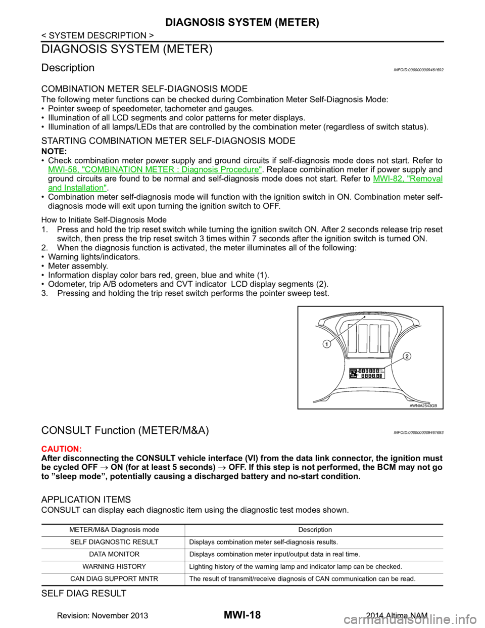
1. Press and hold the trip reset switch while turning the ignition switch ON. After 2 seconds release trip reset switch, then press the trip reset switch 3 times within 7 seconds after the ignition switch is turned ON.
2. When the diagnosis function is activated, the meter illuminates all of the following:
• Warning lights/indicators.
• Meter assembly.
• Information display color bars red, green, blue and white (1).
• Odometer, trip A/B odometers and CVT indicator LCD display segments (2).
3. Pressing and holding the trip reset switch performs the pointer sweep test.
CONSULT Function (METER/M&A)INFOID:0000000009461693
CAUTION:
After disconnecting the CONSULT vehicle interface (VI) from the data link connector, the ignition must
be cycled OFF → ON (for at least 5 seconds) → OFF. If this step is not performed, the BCM may not go
to ”sleep mode”, potentially causing a di scharged battery and no-start condition.
APPLICATION ITEMS
CONSULT can display each diagnostic item using the diagnostic test modes shown.
SELF DIAG RESULT
AWNIA2543GB
METER/M&A Diagnosis mode Description
SELF DIAGNOSTIC RESULT Displays combin ation meter self-diagnosis results.
DATA MONITOR Displays combination meter input/output data in real time.
WARNING HISTORY Lighting history of the warning lamp and indicator lamp can be checked.
CAN DIAG SUPPORT MNTR The result of transmit/receive diagnosis of CAN communication can be read.
Revision: November 20132014 Altima NAMRevision: November 20132014 Altima NAM
Page 3276 of 4801

MWI
DIAGNOSIS SYSTEM (METER)MWI-21
< SYSTEM DESCRIPTION >
C
D E
F
G H
I
J
K L
M B
A
O PSPECIAL FUNCTION
Special menu
W/L ON HISTORY
• “W/L ON HISTORY” indicates the “TIME” when the warning/ indicator lamp is turned on.
• The “TIME” above is:
- 0: The condition that the warning/indicator lamp has been turned on 1 or more times after starting the engine
and waiting for 30 seconds.
- 1 - 39: The number of times the engi ne was restarted after the 0 condition.
- NO W/L ON HISTORY: No warning/indicator lamp history is stored.
NOTE:
• W/L ON HISTORY is not stored for approximately 30 seconds after the engine starts.
• Brake warning lamp does not store any history when the parking brake is applied or the brake fluid level gets
low.
LDW IND
[ON/OFF] Displays [ON/OFF] condition of LDW warning indicator message in the informa-
tion display.
TPMS MALF
[ON/OFF] Displays [ON/OFF] condition of TPMS warning indicator.
Display item [Unit]
MAIN
SIGNALS Description
Display item Description
W/L ON HISTORY Lighting history of warning lamp and indicator lamp can be checked.
Revision: November 20132014 Altima NAMRevision: November 20132014 Altima NAM
Page 3280 of 4801

MWI
COMBINATION METERMWI-25
< ECU DIAGNOSIS INFORMATION >
C
D E
F
G H
I
J
K L
M B
A
O P
4
(R) Ground Steering switch input 2 — — — —
5
(P) Ground ACC — Ignition
switch
ON Ignition switch ACC or ON
power supply Battery voltage
6
(G) Ground Security signal Input Ignition
switch
ON Security indicator ON 0 V
Security indicator OFF 12 V
7
(R) Ground Air bag signal Input Ignition
switch
ON Air bag warning lamp
ON —
Air bag warning lamp
OFF —
8
(W) Ground
Passenger seat belt warn-
ing signal InputIgnition
switch
ON Fastened 12 V
Unfastened 0 V
9
(V) Ground Seat belt buckle switch sig-
nal (driver seat) InputIgnition
switch
ON Fastened 12 V
Unfastened 0 V
11
(R) Ground Alternator signal Input Ignition
switch
ON Charge warning lamp ON 2 V
Charge warning lamp OFF Battery voltage
12
(G) Ground Parking brake switch signal Input Ignition
switch
ON Parking brake applied 0 V
Parking brake released 12 V
18
(BR) Ground AC PD cut Input Ignition
switch
ON Signal ON 0 V
Signal OFF 5 V
21
(BR) —Ignition — Ignition
switch
ON or
START —12 V
22
(G) — Battery power supply — Ignition
switch
OFF —Battery voltage
23
(GR) Ground Illumination control output
signal —Ignition
switch
ON —0 V
24
(W) Ground Steering switch ground — Ignition
switch
ON —0 V
25
(BR) Ground Brake fluid level switch Input Ignition
switch
ON Brake fluid level low 0 V
Brake fluid level normal Battery voltage
26
(R) Ground Fuel level sensor ground — Ignition
switch
ON —0 V
27
(W) Ground Fuel level sensor signal — — — —
30
(L) Ground Ambient sensor signal
(without auto A/C) InputIgnition
switch
ON —
0-5 V
(based on ambient temperature)
Te r m i n a l N o .
(Wire color) Description
ConditionVa l u e
(Approx.)
+ – Signal name Input/
Output
Revision: November 20132014 Altima NAMRevision: November 20132014 Altima NAM
Page 3282 of 4801

MWI
COMBINATION METERMWI-27
< ECU DIAGNOSIS INFORMATION >
C
D E
F
G H
I
J
K L
M B
A
O PFail-SafeINFOID:0000000009461695
FA I L - S A F E
The combination meter activates the fail-safe contro l if CAN communication with each unit is malfunctioning.
DTC IndexINFOID:0000000009461696
52
(P) Ground O/D OFF/SPORT switch Input Ignition
switch
ON O/D OFF switch pressed 0 V
Other than the above 5 V
Te r m i n a l N o .
(Wire color) Description
ConditionVa l u e
(Approx.)
+ – Signal name Input/
Output
Function Specifications
Speedometer Reset to zero by suspending communication.
Tachometer
Engine coolant temperature gauge
Illumination control When suspending communication, changes to nighttime mode.
Information display Odo/trip meter An indicated value is maintained at communications blackout.
Shift position indicator The display turns OFF by suspending communication.
Warning messages The display turns OFF by suspending communication.
Buzzer The buzzer turns OFF by suspending communication.
Warning lamp/indicator lamp ABS warning lamp
The lamp turns ON by suspending communication.
O/D OFF indicator lamp
Slip indicator lamp
Brake warning lamp
Malfunction indicator lamp
VDC OFF indicator lamp
EPS warning lamp
Low tire pressure warning lamp The lamp blinking caused by suspending communication.
High beam indicator lamp
The lamp turns OFF by suspending communication.
Turn signal indicator lamp
Master warning lamp
Front lamp indicator lamp
Lane departure warning
Tail lamp indicator lamp
Air bag warning lamp
The lamp turns off when disconnected.
Charge warning lamp
Seat belt warning lamp
Security indicator lamp
Display contents of CONSULT Diagnostic item is detected when... Refer to
CAN COMM CIRCUIT
[U1000] When combination meter is not transmitting or receiving CAN communication signal for 2
seconds or more. MWI-53
CONTROL UNIT (CAN)
[U1010] When detecting error during the initial diagnosis of the CAN controller of combination
meter. MWI-54
Revision: November 20132014 Altima NAMRevision: November 20132014 Altima NAM