2014 NISSAN TEANA SEC
[x] Cancel search: SECPage 3209 of 4801
ENGINE MAINTENANCE (VQ35DE)MA-25
< PERIODIC MAINTENANCE >
C
D E
F
G H
I
J
K L
M B
MA
N
O A
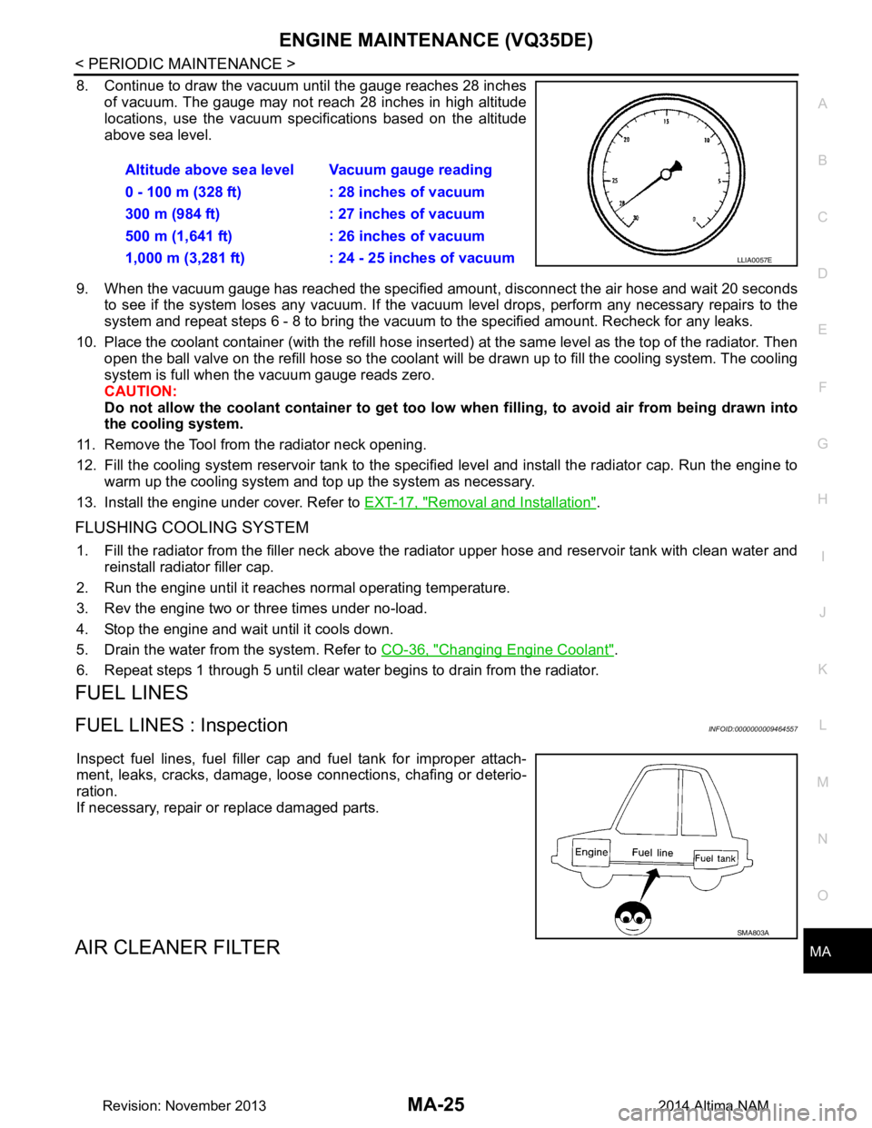
8. Continue to draw the vacuum until the gauge reaches 28 inches
of vacuum. The gauge may not reach 28 inches in high altitude
locations, use the vacuum specifications based on the altitude
above sea level.
9. When the vacuum gauge has reached the specified amount, disconnect the air hose and wait 20 seconds
to see if the system loses any vacuum. If the vacuum level drops, perform any necessary repairs to the
system and repeat steps 6 - 8 to br ing the vacuum to the specified amount. Recheck for any leaks.
10. Place the coolant container (with the refill hose inserted) at the same level as the top of the radiator. Then
open the ball valve on the refill hose so the coolant will be drawn up to fill the cooling system. The cooling
system is full when the vacuum gauge reads zero.
CAUTION:
Do not allow the coolant container to get too low when filling, to avoid air from being drawn into
the cooling system.
11. Remove the Tool from the radiator neck opening.
12. Fill the cooling system reservoir tank to the specif ied level and install the radiator cap. Run the engine to
warm up the cooling system and top up the system as necessary.
13. Install the engine under cover. Refer to EXT-17, "Removal and Installation"
.
FLUSHING COOLING SYSTEM
1. Fill the radiator from the filler neck above the r adiator upper hose and reservoir tank with clean water and
reinstall radiator filler cap.
2. Run the engine until it reaches normal operating temperature.
3. Rev the engine two or three times under no-load.
4. Stop the engine and wait until it cools down.
5. Drain the water from the system. Refer to CO-36, "Changing Engine Coolant"
.
6. Repeat steps 1 through 5 until clear water begins to drain from the radiator.
FUEL LINES
FUEL LINES : InspectionINFOID:0000000009464557
Inspect fuel lines, fuel filler cap and fuel tank for improper attach-
ment, leaks, cracks, damage, loos e connections, chafing or deterio-
ration.
If necessary, repair or replace damaged parts.
AIR CLEANER FILTER
Altitude above sea level Vacuum gauge reading
0 - 100 m (328 ft) : 28 inches of vacuum
300 m (984 ft) : 27 inches of vacuum
500 m (1,641 ft) : 26 inches of vacuum
1,000 m (3,281 ft) : 24 - 25 inches of vacuum
LLIA0057E
SMA803A
Revision: November 20132014 Altima NAM
Page 3214 of 4801
MA-30
< PERIODIC MAINTENANCE >
ENGINE MAINTENANCE (VQ35DE)
• If plug is covered with carbon, a spark plug cleaner may be used.
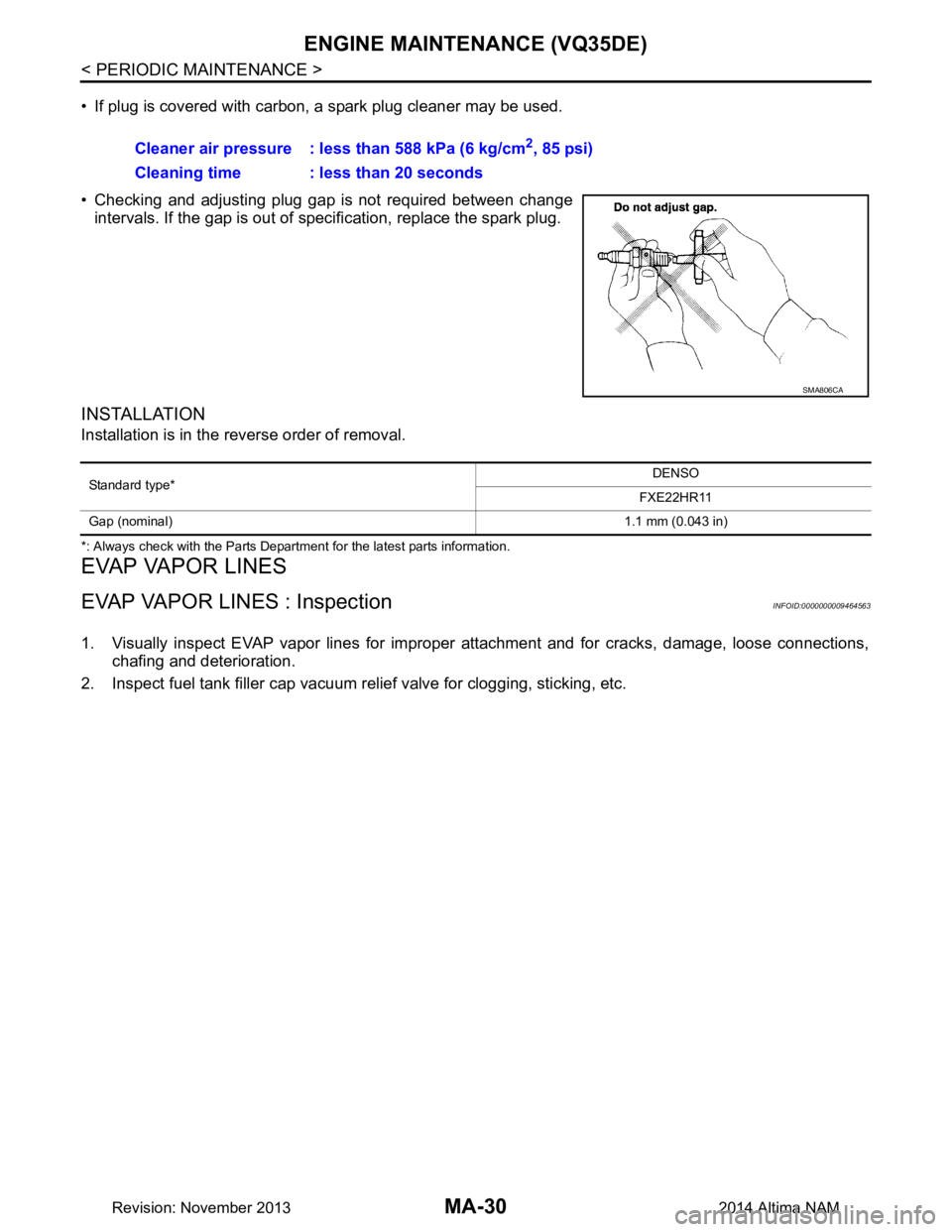
• Checking and adjusting plug gap is not required between change intervals. If the gap is out of s pecification, replace the spark plug.
INSTALLATION
Installation is in the reverse order of removal.
*: Always check with the Parts Department for the latest parts information.
EVAP VAPOR LINES
EVAP VAPOR LINES : InspectionINFOID:0000000009464563
1. Visually inspect EVAP vapor lines for improper attachment and for cracks, damage, loose connections,
chafing and deterioration.
2. Inspect fuel tank filler cap vacuum relief valve for clogging, sticking, etc. Cleaner air pressure : less than 588 kPa (6 kg/cm
2, 85 psi)
Cleaning time : less than 20 seconds
SMA806CA
Standard type* DENSO
FXE22HR11
Gap (nominal) 1.1 mm (0.043 in)
Revision: November 20132014 Altima NAM
Page 3217 of 4801
CHASSIS AND BODY MAINTENANCEMA-33
< PERIODIC MAINTENANCE >
C
D E
F
G H
I
J
K L
M B
MA
N
O A
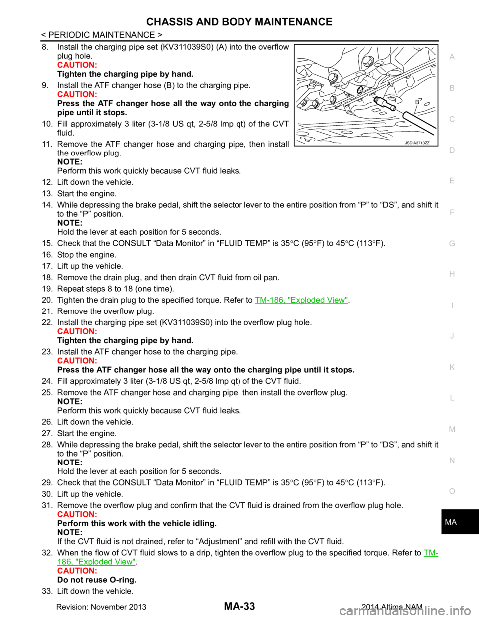
8. Install the charging pipe set (KV311039S0) (A) into the overflow
plug hole.
CAUTION:
Tighten the charging pipe by hand.
9. Install the ATF changer hose (B) to the charging pipe. CAUTION:
Press the ATF changer hose all the way onto the charging
pipe until it stops.
10. Fill approximately 3 liter (3-1/8 US qt, 2-5/8 lmp qt) of the CVT fluid.
11. Remove the ATF changer hose and charging pipe, then install the overflow plug.
NOTE:
Perform this work quickly because CVT fluid leaks.
12. Lift down the vehicle.
13. Start the engine.
14. While depressing the brake pedal, shift the selector leve r to the entire position from “P” to “DS”, and shift it
to the “P” position.
NOTE:
Hold the lever at each position for 5 seconds.
15. Check that the CONSULT “Data Monitor” in “FLUID TEMP” is 35°C (95 °F) to 45 °C (113 °F).
16. Stop the engine.
17. Lift up the vehicle.
18. Remove the drain plug, and then drain CVT fluid from oil pan.
19. Repeat steps 8 to 18 (one time).
20. Tighten the drain plug to the specified torque. Refer to TM-186, "Exploded View"
.
21. Remove the overflow plug.
22. Install the charging pipe set (KV311039S0) into the overflow plug hole. CAUTION:
Tighten the charging pipe by hand.
23. Install the ATF changer hose to the charging pipe. CAUTION:
Press the ATF changer hose all the way onto the charging pipe until it stops.
24. Fill approximately 3 liter (3-1/8 US qt, 2-5/8 lmp qt) of the CVT fluid.
25. Remove the ATF changer hose and charging pipe, then install the overflow plug. NOTE:
Perform this work quickly because CVT fluid leaks.
26. Lift down the vehicle.
27. Start the engine.
28. While depressing the brake pedal, shift the selector leve r to the entire position from “P” to “DS”, and shift it
to the “P” position.
NOTE:
Hold the lever at each position for 5 seconds.
29. Check that the CONSULT “Data Monitor” in “FLUID TEMP” is 35°C (95 °F) to 45 °C (113 °F).
30. Lift up the vehicle.
31. Remove the overflow plug and confirm that the CV T fluid is drained from the overflow plug hole.
CAUTION:
Perform this work with the vehicle idling.
NOTE:
If the CVT fluid is not drained, refer to “Adjustment” and refill with the CVT fluid.
32. When the flow of CVT fluid slows to a drip, tighten the overflow plug to the specified torque. Refer to TM-
186, "Exploded View".
CAUTION:
Do not reuse O-ring.
33. Lift down the vehicle.
JSDIA3713ZZ
Revision: November 20132014 Altima NAM
Page 3218 of 4801
MA-34
< PERIODIC MAINTENANCE >
CHASSIS AND BODY MAINTENANCE
34. Select “Data Monitor” in “TRANSMISSION” using CONSULT.
35. Select “CONFORM CVTF DETERIORTN”.
36. Select “Erase”.
37. Stop the engine.
CVT FLUID : AdjustmentINFOID:0000000009464569
CAUTION:
• During adjustment of the CVT fluid level, check CO NSULT so that the oil temperature may be main-
tained from 35 to 45 °C (95 to 113 °F).
• During adjustment of the CVT fluid level, check that the engine speed is maintaining 500 rpm.
• Use caution when looking into the drain hole as th ere is a risk of dripping fluid entering the eye.
1. Check that the selector lever is in the “P ” position, then completely engage the parking brake.
2. Start the engine.
3. Adjust the CVT fluid temperature to be approximately 40 °C (104 °F).
NOTE:
The CVT fluid is largely affected by temperature. Therefore be sure to use CONSULT and check the
“FLUID TEMP” under “TRANSMISSION” in “Data Monitor” while adjusting.
4. While depressing the brake pedal, shift the selector lever to the entire position from “P” to “DS”, and shift it to the “P” position.
NOTE:
Hold the lever at each position for 5 seconds.
5. Lift up the vehicle.
6. Check that there is no CVT fluid leakage.
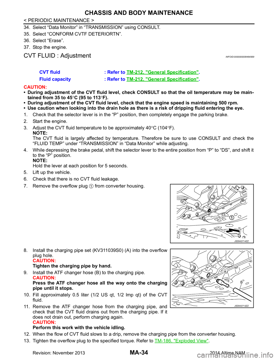
7. Remove the overflow plug from converter housing.
8. Install the charging pipe set (KV311039S0) (A) into the overflow plug hole.
CAUTION:
Tighten the charging pipe by hand.
9. Install the ATF changer hose (B) to the charging pipe. CAUTION:
Press the ATF changer hose all the way onto the charging
pipe until it stops.
10. Fill approximately 0.5 liter (1/2 US qt, 1/2 lmp qt) of the CVT
fluid.
11. Remove the ATF changer hose from the charging pipe, and check that the CVT fluid drains out from the charging pipe. If it
does not drain out, perform charging again.
CAUTION:
Perform this work with the vehicle idling.
12. When the flow of CVT fluid slows to a drip, re move the charging pipe from the converter housing.
13. Tighten the overflow plug to the specified torque. Refer to TM-186, "Exploded View"
.
CVT fluid : Refer to
TM-212, "General Specification"
.
Fluid capacity : Refer to TM-212, "General Specification"
.
JSDIA3714ZZ
JSDIA3713ZZ
Revision: November 20132014 Altima NAM
Page 3220 of 4801
MA-36
< PERIODIC MAINTENANCE >
CHASSIS AND BODY MAINTENANCE
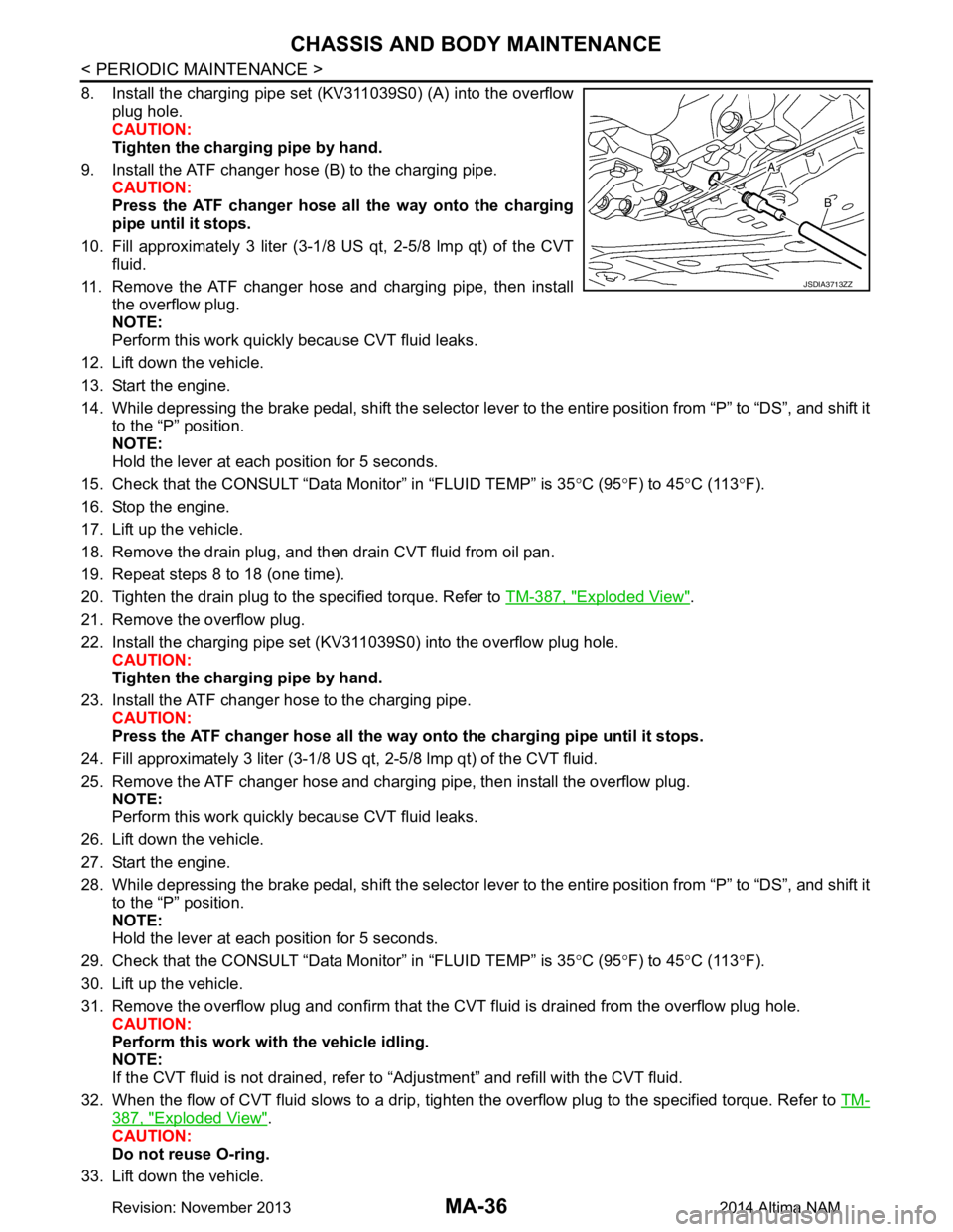
8. Install the charging pipe set (KV311039S0) (A) into the overflowplug hole.
CAUTION:
Tighten the charging pipe by hand.
9. Install the ATF changer hose (B) to the charging pipe. CAUTION:
Press the ATF changer hose all the way onto the charging
pipe until it stops.
10. Fill approximately 3 liter (3-1/8 US qt, 2-5/8 lmp qt) of the CVT
fluid.
11. Remove the ATF changer hose and charging pipe, then install the overflow plug.
NOTE:
Perform this work quickly because CVT fluid leaks.
12. Lift down the vehicle.
13. Start the engine.
14. While depressing the brake pedal, shift the selector lever to the entire position from “P” to “DS”, and shift it to the “P” position.
NOTE:
Hold the lever at each position for 5 seconds.
15. Check that the CONSULT “Data Monitor” in “FLUID TEMP” is 35 °C (95 °F) to 45 °C (113 °F).
16. Stop the engine.
17. Lift up the vehicle.
18. Remove the drain plug, and then drain CVT fluid from oil pan.
19. Repeat steps 8 to 18 (one time).
20. Tighten the drain plug to the specified torque. Refer to TM-387, "Exploded View"
.
21. Remove the overflow plug.
22. Install the charging pipe set (KV311039S0) into the overflow plug hole. CAUTION:
Tighten the charging pipe by hand.
23. Install the ATF changer hose to the charging pipe. CAUTION:
Press the ATF changer hose all the way onto the charging pipe until it stops.
24. Fill approximately 3 liter (3-1/8 US qt, 2-5/8 lmp qt) of the CVT fluid.
25. Remove the ATF changer hose and charging pipe, then install the overflow plug. NOTE:
Perform this work quickly because CVT fluid leaks.
26. Lift down the vehicle.
27. Start the engine.
28. While depressing the brake pedal, shift the selector lever to the entire position from “P” to “DS”, and shift it to the “P” position.
NOTE:
Hold the lever at each position for 5 seconds.
29. Check that the CONSULT “Data Monitor” in “FLUID TEMP” is 35 °C (95 °F) to 45 °C (113 °F).
30. Lift up the vehicle.
31. Remove the overflow plug and confirm that the CV T fluid is drained from the overflow plug hole.
CAUTION:
Perform this work with the vehicle idling.
NOTE:
If the CVT fluid is not drained, refer to “Adjustment” and refill with the CVT fluid.
32. When the flow of CVT fluid slows to a drip, tighten the overflow plug to the specified torque. Refer to TM-
387, "Exploded View".
CAUTION:
Do not reuse O-ring.
33. Lift down the vehicle.
JSDIA3713ZZ
Revision: November 20132014 Altima NAM
Page 3221 of 4801
CHASSIS AND BODY MAINTENANCEMA-37
< PERIODIC MAINTENANCE >
C
D E
F
G H
I
J
K L
M B
MA
N
O A
34. Select “Data Monitor” in “TRANSMISSION” using CONSULT.
35. Select “CONFORM CVTF DETERIORTN”.
36. Select “Erase”.
37. Stop the engine.
CVT FLUID : AdjustmentINFOID:0000000009464573
CAUTION:
• During adjustment of the CVT fluid level, check CO NSULT so that the oil temperature may be main-
tained from 35 to 45 °C (95 to 113 °F).
• During adjustment of the CVT fluid level, check that the engine speed is maintaining 500 rpm.
• Use caution when looking into the drain hole as there is a risk of dripping fluid entering the eye.
1. Check that the selector lever is in the “P ” position, then completely engage the parking brake.
2. Start the engine.
3. Adjust the CVT fluid temperature to be approximately 40 °C (104 °F).
NOTE:
The CVT fluid is largely affected by temperature. Therefore be sure to use CONSULT and check the
“FLUID TEMP” under “TRA NSMISSION” in “Data Monitor” while adjusting.
4. While depressing the brake pedal, shift the selector leve r to the entire position from “P” to “DS”, and shift it
to the “P” position.
NOTE:
Hold the lever at each position for 5 seconds.
5. Lift up the vehicle.
6. Check that there is no CVT fluid leakage.
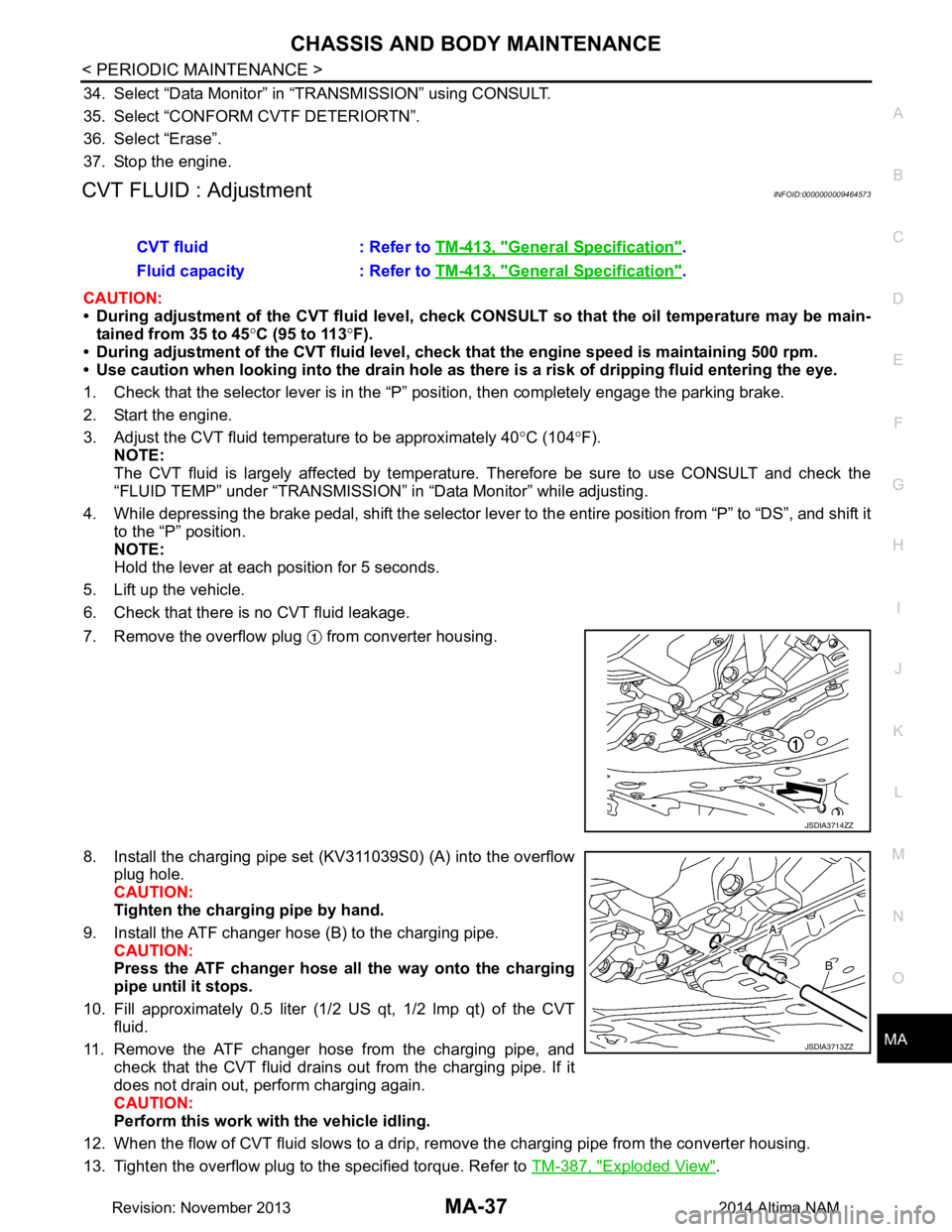
7. Remove the overflow plug from converter housing.
8. Install the charging pipe set (KV311039S0) (A) into the overflow plug hole.
CAUTION:
Tighten the charging pipe by hand.
9. Install the ATF changer hose (B) to the charging pipe. CAUTION:
Press the ATF changer hose all the way onto the charging
pipe until it stops.
10. Fill approximately 0.5 liter (1/2 US qt, 1/2 lmp qt) of the CVT
fluid.
11. Remove the ATF changer hose from the charging pipe, and check that the CVT fluid drains out from the charging pipe. If it
does not drain out, perform charging again.
CAUTION:
Perform this work with the vehicle idling.
12. When the flow of CVT fluid slows to a drip, re move the charging pipe from the converter housing.
13. Tighten the overflow plug to the specified torque. Refer to TM-387, "Exploded View"
.
CVT fluid : Refer to
TM-413, "General Specification"
.
Fluid capacity : Refer to TM-413, "General Specification"
.
JSDIA3714ZZ
JSDIA3713ZZ
Revision: November 20132014 Altima NAM
Page 3225 of 4801
CHASSIS AND BODY MAINTENANCEMA-41
< PERIODIC MAINTENANCE >
C
D E
F
G H
I
J
K L
M B
MA
N
O A
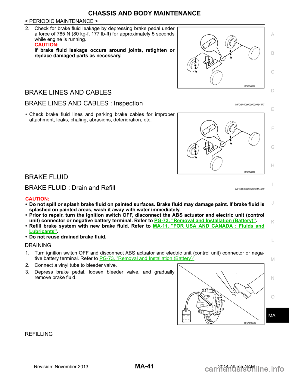
2. Check for brake fluid leakage by depressing brake pedal under
a force of 785 N (80 kg-f, 177 lb-ft) for approximately 5 seconds
while engine is running.
CAUTION:
If brake fluid leakage occurs around joints, retighten or
replace damaged parts as necessary.
BRAKE LINES AND CABLES
BRAKE LINES AND CABLES : InspectionINFOID:0000000009464577
• Check brake fluid lines and parking brake cables for improper attachment, leaks, chafing, abrasions, deterioration, etc.
BRAKE FLUID
BRAKE FLUID : Drain and RefillINFOID:0000000009464578
CAUTION:
• Do not spill or splash brake fluid on painted surf aces. Brake fluid may damage paint. If brake fluid is
splashed on painted areas, wash it away with water immediately.
• Prior to repair, turn the ignition switch OFF, disconnect the ABS actuator and electric unit (control
unit) connector or negative battery terminal. Refer to PG-73, "Removal and Installation (Battery)"
.
• Refill brake system with new brake fluid. Refer to MA-11, "FOR USA AND CANADA : Fluids and
Lubricants".
• Do not reuse drained brake fluid.
DRAINING
1. Turn ignition switch OFF and disconnect ABS actuat or and electric unit (control unit) connector or nega-
tive battery terminal. Refer to PG-73, "Removal and Installation (Battery)"
.
2. Connect a vinyl tube to bleeder valve.
3. Depress brake pedal, loosen bleeder valve, and gradually remove brake fluid.
REFILLING
SBR389C
SBR389C
BRA0007D
Revision: November 20132014 Altima NAM
Page 3226 of 4801
MA-42
< PERIODIC MAINTENANCE >
CHASSIS AND BODY MAINTENANCE
1. Make sure no foreign material is in the reservoir, and refill withnew brake fluid.
CAUTION:
Do not reuse drained brake fluid.
2. Refill the brake system as follows: • Depress the brake pedal.
• Loosen bleeder valve.
• Slowly depress brake pedal to 2/3 of the brake pedal full stroke.
• Tighten bleeder valve.
• Release brake pedal.
Repeat this operation at intervals of two or three seconds until
all old brake fluid is discharged. Add new brake flui d to master cylinder reservoir sub tank frequently.
CAUTION:
Do not allow master cylinder reservoir to empt y as this may cause damage to master cylinder
internal components.
3. Bleed the air out of the brake hydraulic system. Refer to BR-14, "Bleeding Brake System"
.
DISC BRAKE
DISC BRAKE : Front Brake PadINFOID:0000000009464579
DISC BRAKE : InspectionINFOID:0000000009464580
PA D W E A R
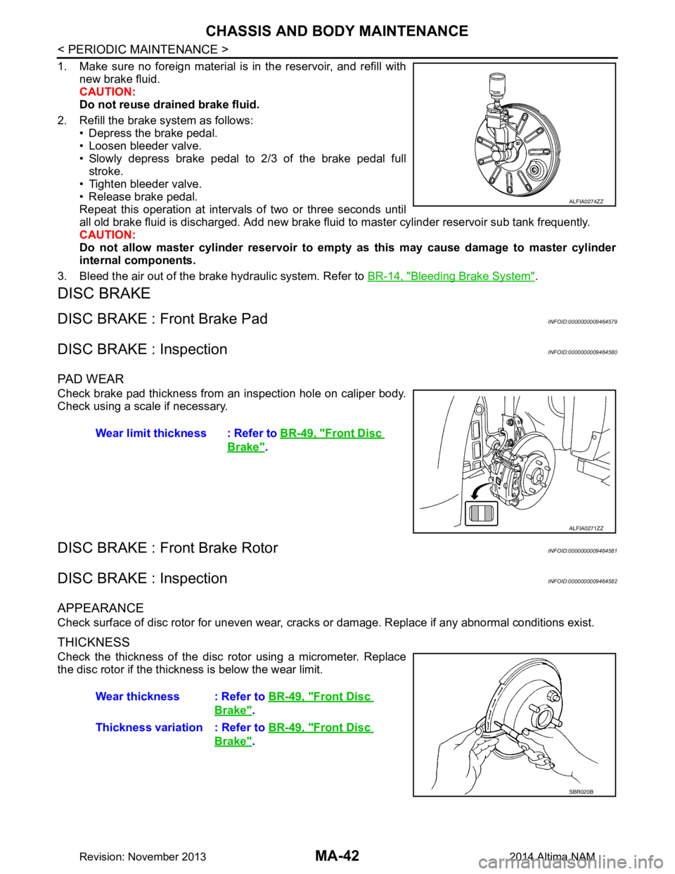
Check brake pad thickness from an inspection hole on caliper body.
Check using a scale if necessary.
DISC BRAKE : Front Brake RotorINFOID:0000000009464581
DISC BRAKE : InspectionINFOID:0000000009464582
APPEARANCE
Check surface of disc rotor for uneven wear, cracks or damage. Replace if any abnormal conditions exist.
THICKNESS
Check the thickness of the disc rotor using a micrometer. Replace
the disc rotor if the thickness is below the wear limit.
ALFIA0274ZZ
Wear limit thickness : Refer to BR-49, "Front Disc
Brake".
ALFIA0271ZZ
Wear thickness : Refer to BR-49, "Front Disc
Brake".
Thickness variation : Refer to BR-49, "Front Disc
Brake".
SBR020B
Revision: November 20132014 Altima NAM