2014 NISSAN TEANA height
[x] Cancel search: heightPage 3711 of 4801
RF-46
< REMOVAL AND INSTALLATION >
MOONROOF UNIT ASSEMBLY
d. Tighten glass lid bolts.NOTE:
First tighten left front bolt, then right rear bolt on glass lid to prevent uneven torque while tightening
remaining bolts.
e. After any adjustment, check moonroof operation and glass lid alignment.
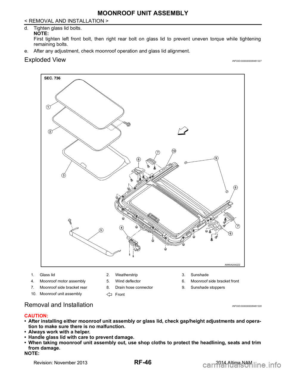
Exploded ViewINFOID:0000000009461327
Removal and InstallationINFOID:0000000009461328
CAUTION:
• After installing either moonro of unit assembly or glass lid, check gap/height adjustments and opera-
tion to make sure there is no malfunction.
• Always work with a helper.
• Handle glass lid with care to prevent damage.
• When taking moonroof unit assembly out, use shop cloths to protect the headlining, seats and trim
from damage.
NOTE:
1. Glass lid 2. Weatherstrip 3. Sunshade
4. Moonroof motor assembly 5. Wind deflector 6. Moonroof side bracket front
7. Moonroof side bracket rear 8. Drain hose connector 9. Sunshade stoppers
10. Moonroof unit assembly Front
AWKIA2042ZZ
Revision: November 20132014 Altima NAMRevision: November 20132014 Altima NAM
Page 3718 of 4801

RSU-1
SUSPENSION
C
D
F
G H
I
J
K L
M
SECTION RSU
A
B
RSU
N
O PCONTENTS
REAR SUSPENSION
PRECAUTION ................ ...............................2
PRECAUTIONS .............................................. .....2
Precaution for Supplemental Restraint System
(SRS) "AIR BAG" and "SEAT BELT PRE-TEN-
SIONER" ............................................................. ......
2
General Precautions .................................................2
PREPARATION ............................................3
PREPARATION .............................................. .....3
Commercial Service Tool .................................... ......3
SYMPTOM DIAGNOSIS ...............................4
NOISE, VIBRATION AND HARSHNESS
(NVH) TROUBLESHOOTING ........................ .....
4
NVH Troubleshooting Chart ................................ ......4
PERIODIC MAINTENANCE ..........................5
REAR SUSPENSION ASSEMBLY ................ .....5
On-vehicle Service .............................................. ......5
Inspection ..................................................................5
Inspection and Adjustment ........................................5
UNIT REMOVAL AND INSTALLATION .......8
REAR SUSPENSION ASSEMBLY ................ .....8
Exploded View .................................................... ......8
Removal and Installation ..................................... .....8
REMOVAL AND INSTALLATION ...............12
REAR LOWER LINK & COIL SPRING .............12
Removal and Installation ..................................... ....12
SHOCK ABSORBER ........................................13
Exploded View .........................................................13
Removal and Installation .........................................13
Disassembly and Assembly .....................................14
Disposal ...................................................................14
REAR STABILIZER ..........................................15
Exploded View .........................................................15
Removal and Installation .........................................15
SUSPENSION ARM ..........................................16
Exploded View .........................................................16
Removal and Installation .........................................16
SERVICE DATA AND SPECIFICATIONS
(SDS) ............... .............................................
17
SERVICE DATA AND SPECIFICATIONS
(SDS) .................................................................
17
General Specification (Rear) ............................... ....17
Wheel Alignment (Unladen*) ...................................17
Wheelarch Height (Unladen*1) ................................17
Revision: November 20132014 Altima NAM
Page 3722 of 4801
REAR SUSPENSION ASSEMBLYRSU-5
< PERIODIC MAINTENANCE >
C
D
F
G H
I
J
K L
M A
B
RSU
N
O P
PERIODIC MAINTENANCE
REAR SUSPENSION ASSEMBLY
On-vehicle ServiceINFOID:0000000009464454
• Check the suspension parts for excessive play, cracks, wear or damage. Shake each rear wheel to check for
excessive play.
• Retighten all nuts and bolts to the specified torque.
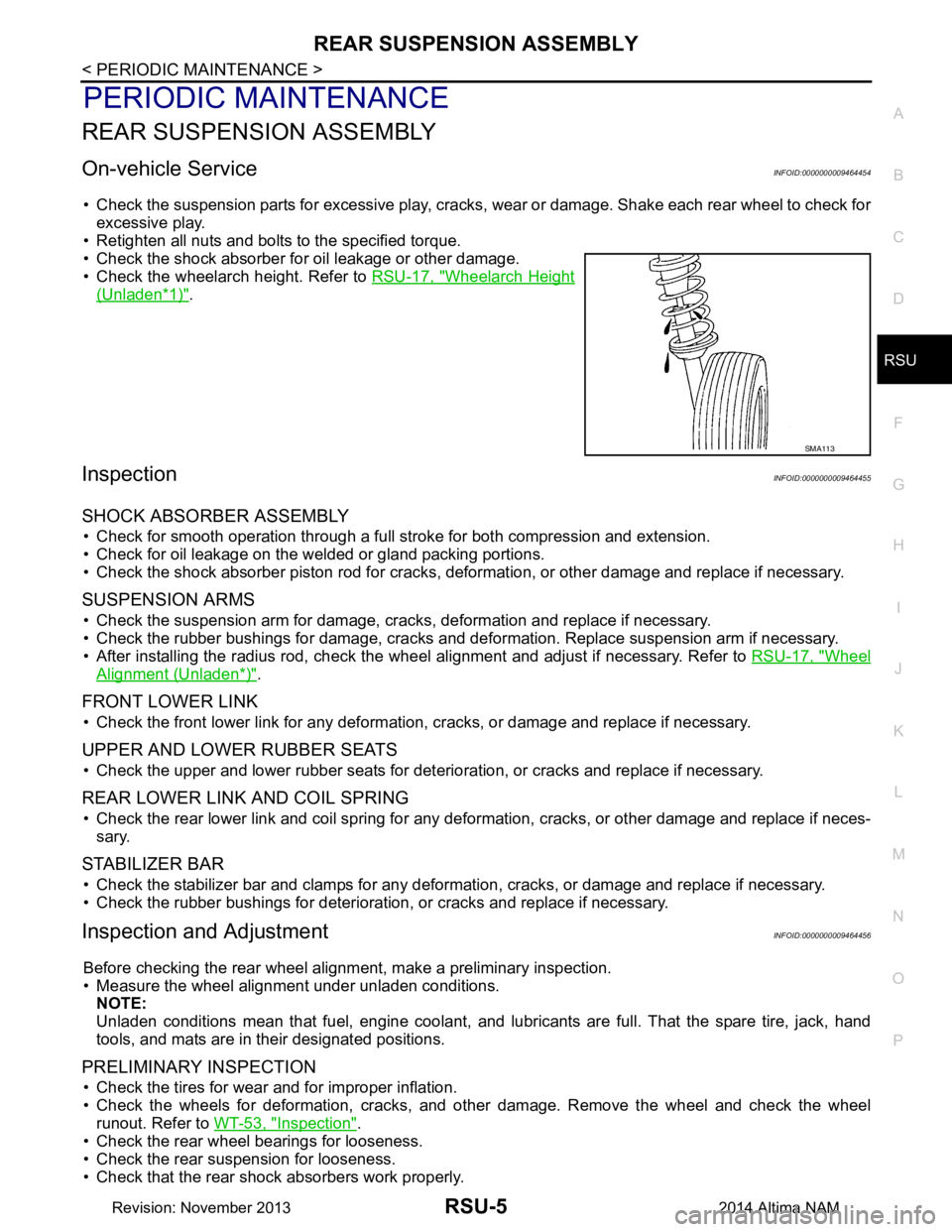
• Check the shock absorber for oil leakage or other damage.
• Check the wheelarch height. Refer to RSU-17, "Wheelarch Height
(Unladen*1)".
InspectionINFOID:0000000009464455
SHOCK ABSORBER ASSEMBLY
• Check for smooth operation through a full stroke for both compression and extension.
• Check for oil leakage on the welded or gland packing portions.
• Check the shock absorber piston r od for cracks, deformation, or other damage and replace if necessary.
SUSPENSION ARMS
• Check the suspension arm for damage, cracks, deformation and replace if necessary.
• Check the rubber bushings for damage, cracks and defo rmation. Replace suspension arm if necessary.
• After installing the radius rod, check the wheel alignment and adjust if necessary. Refer to RSU-17, "Wheel
Alignment (Unladen*)".
FRONT LOWER LINK
• Check the front lower link for any deformation, cracks, or damage and replace if necessary.
UPPER AND LOWER RUBBER SEATS
• Check the upper and lower rubber seats for deterioration, or cracks and replace if necessary.
REAR LOWER LINK AND COIL SPRING
• Check the rear lower link and coil spring for any def ormation, cracks, or other damage and replace if neces-
sary.
STABILIZER BAR
• Check the stabilizer bar and clamps for any deformation, cracks, or damage and replace if necessary.
• Check the rubber bushings for deterioration, or cracks and replace if necessary.
Inspection and AdjustmentINFOID:0000000009464456
Before checking the rear wheel ali gnment, make a preliminary inspection.
• Measure the wheel alignment under unladen conditions. NOTE:
Unladen conditions mean that fuel, engine coolant, and l ubricants are full. That the spare tire, jack, hand
tools, and mats are in their designated positions.
PRELIMINARY INSPECTION
• Check the tires for wear and for improper inflation.
• Check the wheels for deformation, cracks, and ot her damage. Remove the wheel and check the wheel
runout. Refer to WT-53, "Inspection"
.
• Check the rear wheel bearings for looseness.
• Check the rear suspension for looseness.
• Check that the rear shock absorbers work properly.
SMA113
Revision: November 20132014 Altima NAM
Page 3723 of 4801
RSU-6
< PERIODIC MAINTENANCE >
REAR SUSPENSION ASSEMBLY
• Check the wheelarch height in the unladen condition. Refer to RSU-17, "Wheelarch Height (Unladen*1)".
GENERAL INFORMATION AND RECOMMENDATIONS
1. A Four-Wheel Thrust Alignment should be performed.
• This type of alignment is recommended for any NISSAN vehicle.
• The four-wheel “thrust” process helps ensure that the vehicle is properly aligned and the steering wheel
is centered.
• The alignment machine itself should be ca pable of accepting any NISSAN vehicle.
• The alignment machine should be checked to ensure that it is level.
2. Make sure the alignment machine is properly calibrated. • Your alignment machine should be regularly calibrated in order to give correct information.
• Check with the manufacturer of your specific al ignment machine for their recommended Service/Cali-
bration Schedule.
THE ALIGNMENT PROCESS
IMPORTANT: Use only the alignment specifications listed in this Service Manual. Refer to RSU-17,
"Wheelarch Height (Unladen*1)".
1. When displaying the alignment settings, many alignm ent machines use “indicators”: (Green/red, plus or
minus, Go/No Go). Do NOT use these indicators.
• The alignment specifications programmed into your alignment machine that operate these indicators
may not be correct.
• This may result in an ERROR.
2. Most camera-type alignment machines are equipped with both "Rolling Compensation" method and optional "Jacking Compensation" method to "com pensate" the alignment targets or head units.
"Rolling Compensation" is the preferred method.
• If using the "Rolling Compensation" method, after installing the alignment targets or head units, push or pull on the rear wheel to move the vehicle. Do not push or pull the vehicle body.
• If using the "Jacking Compensation" method, after in stalling the alignment targets or head units, raise
the vehicle and rotate the wheels 1/2 turn both ways.
NOTE:
Do not use the "Rolling Compensation" method if you are using sensor-type alignment equipment.
• Follow all instructions for the alignment machine you are using for more information.
CAMBER and TOE
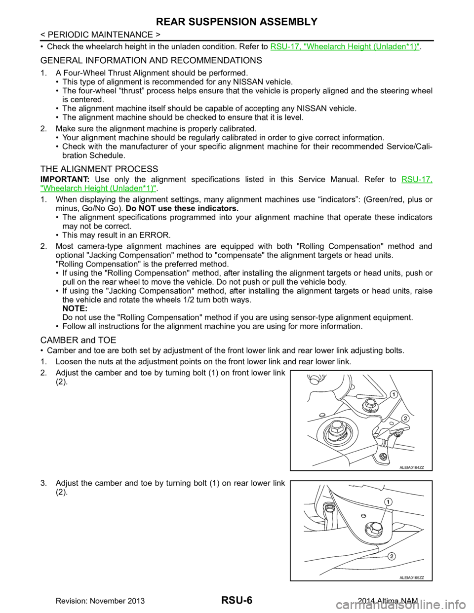
• Camber and toe are both set by adjustment of the fr ont lower link and rear lower link adjusting bolts.
1. Loosen the nuts at the adjustment points on the front lower link and rear lower link.
2. Adjust the camber and toe by turning bolt (1) on front lower link (2).
3. Adjust the camber and toe by turning bolt (1) on rear lower link (2).
ALEIA0164ZZ
ALEIA0165ZZ
Revision: November 20132014 Altima NAM
Page 3734 of 4801
SERVICE DATA AND SPECIFICATIONS (SDS)RSU-17
< SERVICE DATA AND SPECIFICATIONS (SDS)
C
D
F
G H
I
J
K L
M A
B
RSU
N
O P
SERVICE DATA AND SPECIFICATIONS (SDS)
SERVICE DATA AND SPECIFICATIONS (SDS)
General Specification (Rear)INFOID:0000000009464468
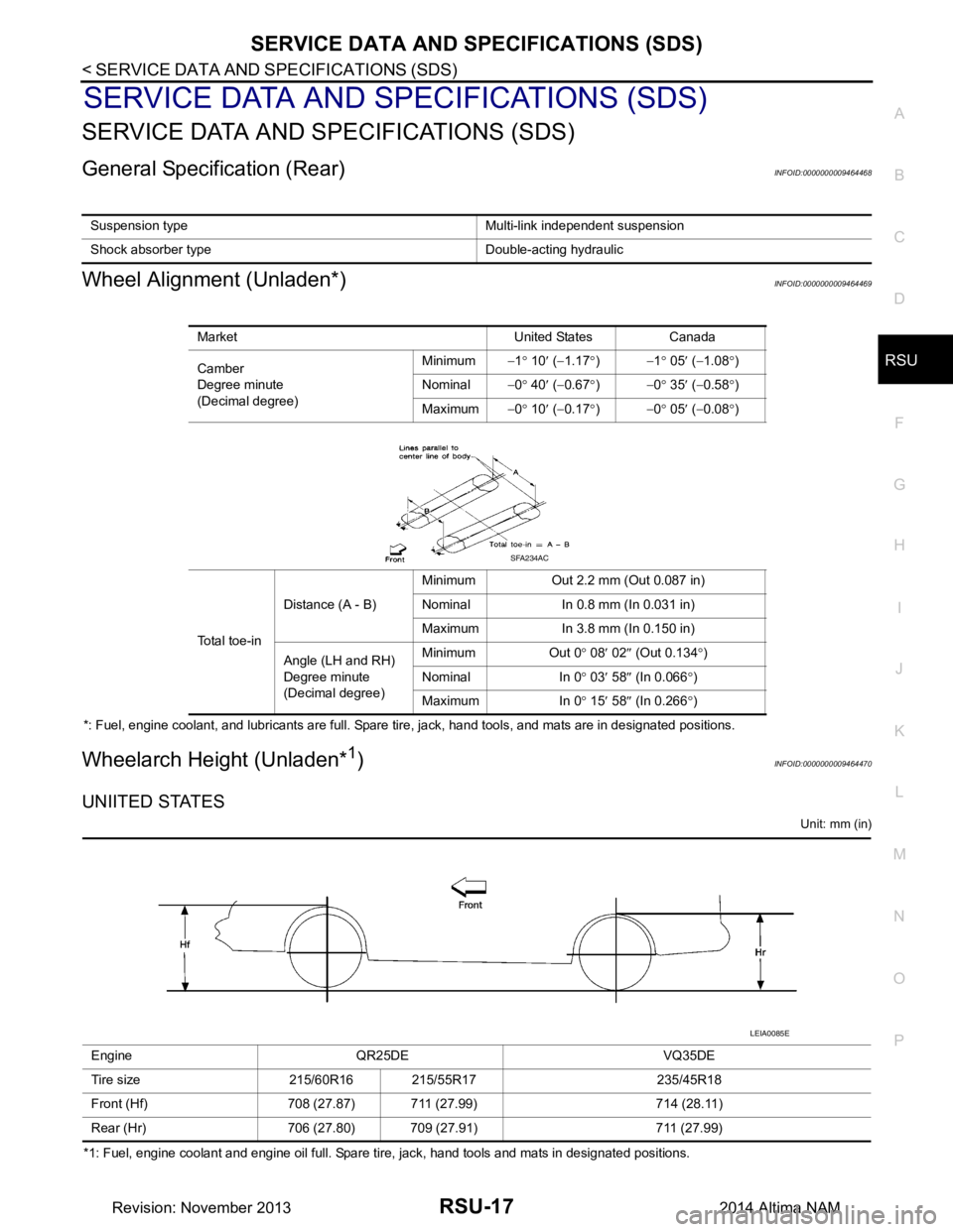
Wheel Alignment (Unladen*)INFOID:0000000009464469
*: Fuel, engine coolant, and lubricants are full. Spare tire, jack, hand tools, and mats are in designated positions.
Wheelarch Height (Unladen*1)INFOID:0000000009464470
UNIITED STATES
Unit: mm (in)
*1: Fuel, engine coolant and engine oil full. Spare tire, jack, hand tools and mats in designated positions. Suspension type Multi-link independent suspension
Shock absorber type Double-acting hydraulic
Market United States Canada
Camber
Degree minute
(Decimal degree) Minimum
−1° 10 ′ ( −1.17 °) −1 ° 05 ′ ( −1.08 °)
Nominal −0° 40 ′ ( −0.67 °) −0 ° 35 ′ ( −0.58 °)
Maximum −0° 10 ′ ( −0.17 °) −0 ° 05 ′ ( −0.08 °)
Total toe-in Distance (A - B)
Minimum Out 2.2 mm (Out 0.087 in)
Nominal In 0.8 mm (In 0.031 in)
Maximum In 3.8 mm (In 0.150 in)
Angle (LH and RH)
Degree minute
(Decimal degree) Minimum Out 0
° 08 ′ 02 ″ (Out 0.134 °)
Nominal In 0 ° 03 ′ 58 ″ (In 0.066 °)
Maximum In 0 ° 15 ′ 58 ″ (In 0.266 °)
SFA234AC
Engine QR25DE VQ35DE
Tire size 215/60R16 215/55R17 235/45R18
Front (Hf) 708 (27.87) 711 (27.99) 714 (28.11)
Rear (Hr) 706 (27.80) 709 (27.91) 711 (27.99)
LEIA0085E
Revision: November 20132014 Altima NAM
Page 3740 of 4801
COMPONENT INSPECTIONSB-5
< BASIC INSPECTION >
C
D E
F
G
I
J
K L
M A
B
SB
N
O P
BASIC INSPECTION
COMPONENT INSPECTION
InspectionINFOID:0000000009462960
AFTER A COLLISION
WARNING:
Inspect all seat belt assemblies in cluding retractors and attaching hardware after any collision.
NISSAN/INFINITI recommends that all seat belt assemblies in use during a collision be replaced
unless the collision was minor and th e belts show no damage and continue to operate properly. Fail-
ure to do so could result in serious personal inju ry in an accident. Seat belt assemblies not in use dur-
ing a collision should also be replaced if either da mage or improper operation is noted. Seat belt pre-
tensioners should be replaced even if the seat belts are not in use during a frontal collision in which
the air bags are deployed.
Replace any seat belt assembly (including anchor bolts) if:
• The seat belt was in use at the time of a collision (except for minor collisions and the belts, retractors and
buckles show no damage and continue to operate properly).
• The seat belt was damaged in an accident (i.e. torn webbing, bent retractor or guide, etc.).
• The seat belt attaching point is damaged in an accident . Inspect the seat belt attaching area for damage or
distortion and repair if necessary before installing a new seat belt assembly.
• Anchor bolts are deformed or worn out.
• The seat belt pre-tensioner should be replaced even if t he seat belts are not in use during the collision in
which the air bags are deployed.
PRELIMINARY CHECKS
1. Check the seat belt warning lamp for proper operation per the following:
a. Turn ignition switch ON. The seat belt warning lamp should illuminate.
b. Fasten driver seat belt. The seat belt warning lamp should turn OFF.
2. If the air bag warning lamp is blinking, perform self-diagnosis with CONSULT and air bag warning lamp. Refer to SRC-17, "Trouble Diagnosis without CONSULT"
.
3. Check that the seat belt retractor, seat belt anchor and buckle bolts are tightened firmly.
4. Check the shoulder seat belt guide and shoulder belt height adjuster for front seats. Check that guide
swivels freely and that webbing lays flat and does not bind in guide. Check that height adjuster operates
properly and holds securely.
5. Check retractor operation:
a. Fully extend the seat belt webbing and check for twists, tears or other damage.
b. Allow the seat belt to retract. Check that webbing retu rns smoothly and completely into the retractor. If the
seat belt does not return smoothly, wipe the inside of t he loops with a clean paper cloth. Dirt build-up in the
loops of the upper anchors can cause t he seat belts to retract slowly.
c. Fasten the seat belt. Check that seat belt returns sm oothly and completely to the retractor. If the webbing
does not return smoothly, the cause may be an accu mulation of dust or dirt. Use the “SEAT BELT TAPE
SET” and perform the following steps.
d. Inspect the front seat belt D-ring anchor 1. Pull the seat belt out to a length of 500 mm (19.69 in) or more.
2. Hold the seat belt at the center pillar webbing opening with a clip or other device.
3. Pass a thin wire through the D-ring anchor webbing opening. Hold both ends of the wire and pull it tightly while moving it up and down several times along the webbing opening surface to remove dirt
stuck there.
4. Any dirt that cannot be removed with the wire can be removed by cleaning the opening with a clean
cloth.
5. Apply tape at the point where the webbing contacts the D-ring anchor webbing opening. NOTE:
Apply the tape so that there is no slack or wrinkling.
6. Remove the clip holding the seat belt and check that the webbing returns smoothly.
6. Repeat steps above if necessary to check the other seat belts.
Revision: November 20132014 Altima NAM
Page 3743 of 4801
SB-8
< REMOVAL AND INSTALLATION >
FRONT SEAT BELT
REMOVAL AND INSTALLATION
FRONT SEAT BELT
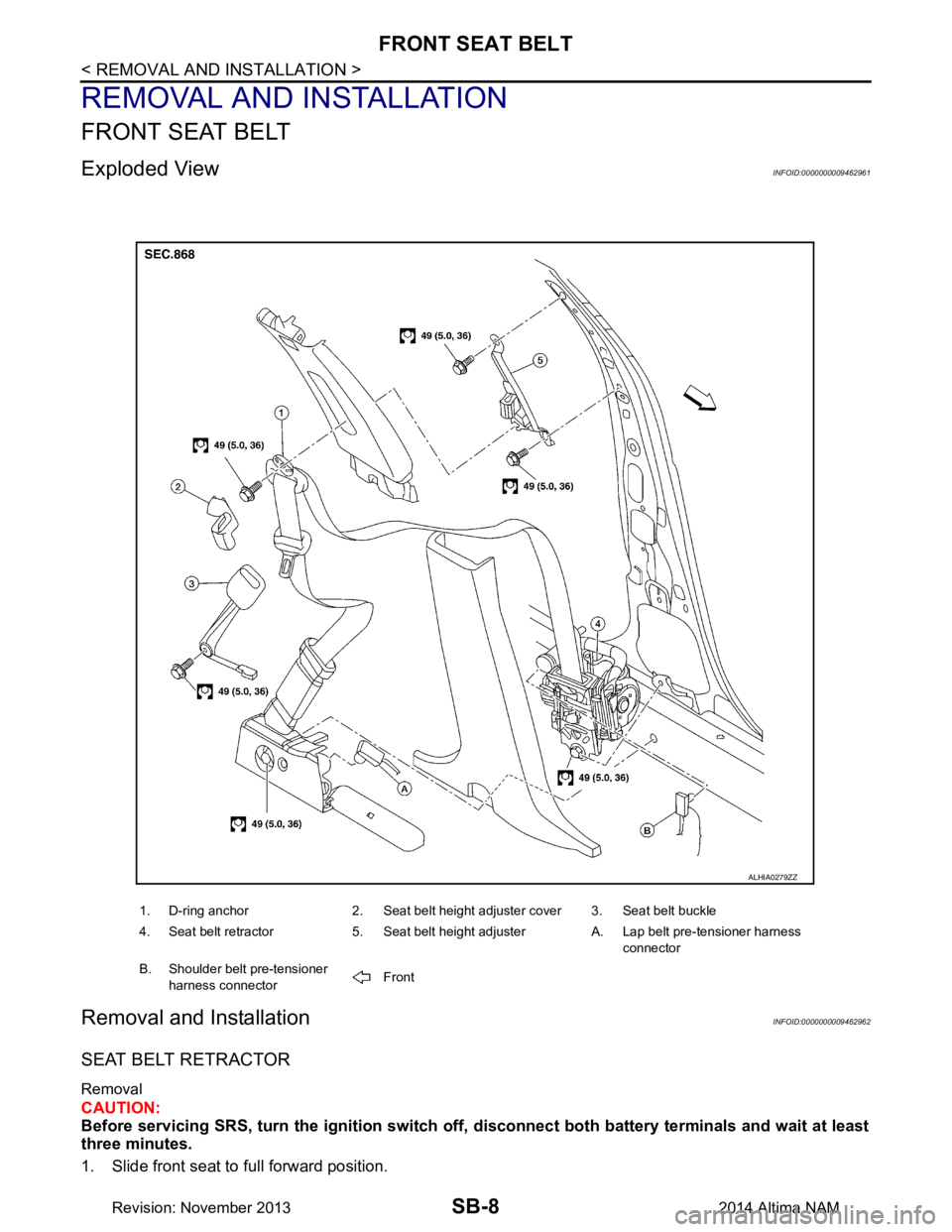
Exploded ViewINFOID:0000000009462961
Removal and InstallationINFOID:0000000009462962
SEAT BELT RETRACTOR
Removal
CAUTION:
Before servicing SRS, turn the igni tion switch off, disconnect both battery terminals and wait at least
three minutes.
1. Slide front seat to full forward position.
1. D-ring anchor 2. Seat belt height adjuster cover 3. Seat belt buckle
4. Seat belt retractor 5. Seat belt height adjuster A. Lap belt pre-tensioner harness connector
B. Shoulder belt pre-tensioner harness connector Front
ALHIA0279ZZ
Revision: November 20132014 Altima NAM
Page 3744 of 4801
FRONT SEAT BELTSB-9
< REMOVAL AND INSTALLATION >
C
D E
F
G
I
J
K L
M A
B
SB
N
O P
2. Disconnect both negative and positive battery terminals, then wait at least three minutes. Refer to PG-73,
"Removal and Installation (Battery)".
3. Remove center pillar lower finisher. Refer to INT-23, "CENTER PILLAR LOWER FINISHER : Removal
and Installation".
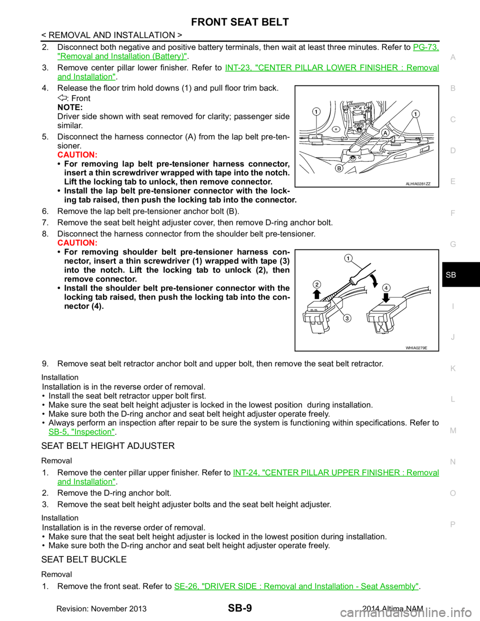
4. Release the floor trim hold downs (1) and pull floor trim back. : Front
NOTE:
Driver side shown with seat removed for clarity; passenger side
similar.
5. Disconnect the harness connector (A ) from the lap belt pre-ten-
sioner.
CAUTION:
• For removing lap belt pre-tensioner harness connector, insert a thin screwdriver wrappe d with tape into the notch.
Lift the locking tab to un lock, then remove connector.
• Install the lap belt pre-tensioner connector with the lock- ing tab raised, then push the locking tab into the connector.
6. Remove the lap belt pre-tensioner anchor bolt (B).
7. Remove the seat belt height adjuster cover, then remove D-ring anchor bolt.
8. Disconnect the harness connector from the shoulder belt pre-tensioner. CAUTION:
• For removing shoulder belt pre-tensioner harness con- nector, insert a thin screwdriver (1) wrapped with tape (3)
into the notch. Lift the lo cking tab to unlock (2), then
remove connector.
• Install the shoulder belt pr e-tensioner connector with the
locking tab raised, then push the locking tab into the con-
nector (4).
9. Remove seat belt retractor anchor bolt and upper bolt, then remove the seat belt retractor.
Installation
Installation is in the reverse order of removal.
• Install the seat belt retractor upper bolt first.
• Make sure the seat belt height adjuster is lock ed in the lowest position during installation.
• Make sure both the D-ring anchor and seat belt height adjuster operate freely.
• Always perform an inspection after repair to be sure t he system is functioning within specifications. Refer to
SB-5, "Inspection"
.
SEAT BELT HEIGHT ADJUSTER
Removal
1. Remove the center pillar upper finisher. Refer to INT-24, "CENTER PILLAR UPPER FINISHER : Removal
and Installation".
2. Remove the D-ring anchor bolt.
3. Remove the seat belt height adjuster bolts and the seat belt height adjuster.
Installation
Installation is in the reverse order of removal.
• Make sure that the seat belt height adjuster is locked in the lowest position during installation.
• Make sure both the D-ring anchor and seat belt height adjuster operate freely.
SEAT BELT BUCKLE
Removal
1. Remove the front seat. Refer to SE-26, "DRIVER SIDE : Removal and Installation - Seat Assembly".
ALHIA0281ZZ
WHIA0279E
Revision: November 20132014 Altima NAM