2014 NISSAN TEANA height
[x] Cancel search: heightPage 2433 of 4801
FRONT BUMPEREXT-19
< REMOVAL AND INSTALLATION >
C
D E
F
G H
I
J
L
M A
B
EXT
N
O P
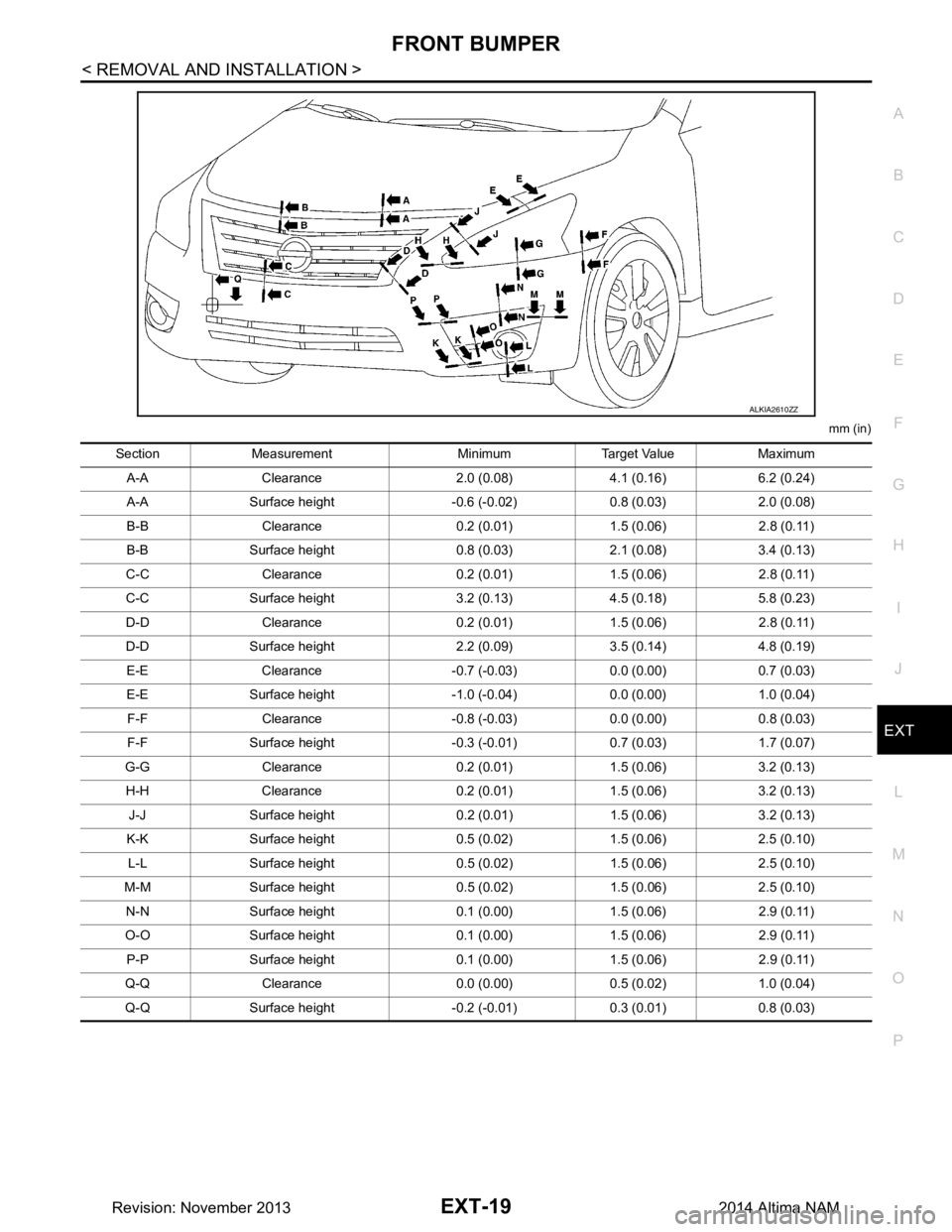
mm (in)
ALKIA2610ZZ
Section Measurement Minimum Target Value Maximum A-A Clearance 2.0 (0.08) 4.1 (0.16) 6.2 (0.24)
A-A Surface height -0.6 (-0.02) 0.8 (0.03) 2.0 (0.08)
B-B Clearance 0.2 (0.01) 1.5 (0.06) 2.8 (0.11)
B-B Surface height 0.8 (0.03) 2.1 (0.08) 3.4 (0.13)
C-C Clearance 0.2 (0.01) 1.5 (0.06) 2.8 (0.11)
C-C Surface height 3.2 (0.13) 4.5 (0.18) 5.8 (0.23)
D-D Clearance 0.2 (0.01) 1.5 (0.06) 2.8 (0.11)
D-D Surface height 2.2 (0.09) 3.5 (0.14) 4.8 (0.19) E-E Clearance -0.7 (-0.03) 0.0 (0.00) 0.7 (0.03)
E-E Surface height -1.0 (-0.04) 0.0 (0.00) 1.0 (0.04) F-F Clearance -0.8 (-0.03) 0.0 (0.00) 0.8 (0.03)
F-F Surface height -0.3 (-0.01) 0.7 (0.03) 1.7 (0.07)
G-G Clearance 0.2 (0.01) 1.5 (0.06) 3.2 (0.13)
H-H Clearance 0.2 (0.01) 1.5 (0.06) 3.2 (0.13) J-J Surface height 0.2 (0.01) 1.5 (0.06) 3.2 (0.13)
K-K Surface height 0.5 (0.02) 1.5 (0.06) 2.5 (0.10) L-L Surface height 0.5 (0.02) 1.5 (0.06) 2.5 (0.10)
M-M Surface height 0.5 (0.02) 1.5 (0.06) 2.5 (0.10) N-N Surface height 0.1 (0.00) 1.5 (0.06) 2.9 (0.11)
O-O Surface height 0.1 (0.00) 1.5 (0.06) 2.9 (0.11) P-P Surface height 0.1 (0.00) 1.5 (0.06) 2.9 (0.11)
Q-Q Clearance 0.0 (0.00) 0.5 (0.02) 1.0 (0.04)
Q-Q Surface height -0.2 (-0.01) 0.3 (0.01) 0.8 (0.03)
Revision: November 20132014 Altima NAM
Page 2436 of 4801
EXT-22
< REMOVAL AND INSTALLATION >
REAR BUMPER
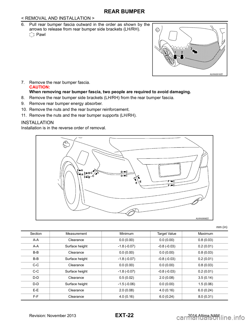
6. Pull rear bumper fascia outward in the order as shown by thearrows to release from rear bumper side brackets (LH/RH).
: Pawl
7. Remove the rear bumper fascia. CAUTION:
When removing rear bumper fascia, two people are required to avoid damaging.
8. Remove the rear bumper side brackets (LH/RH) from the rear bumper fascia.
9. Remove rear bumper energy absorber.
10. Remove the nuts and the rear bumper reinforcement.
11. Remove the nuts and the rear bumper supports (LH/RH).
INSTALLATION
Installation is in the reverse order of removal.
mm (in)
ALKIA2616ZZ
ALKIA2658ZZ
Section Measurement Minimum Target Value Maximum
A-A Clearance 0.0 (0.00) 0.0 (0.00) 0.8 (0.03)
A-A Surface height -1.8 (-0.07) -0.8 (-0.03) 0.2 (0.01)
B-B Clearance 0.0 (0.00) 0.0 (0.00) 0.8 (0.03)
B-B Surface height -1.8 (-0.07) -0.8 (-0.03) 0.2 (0.01)
C-C Clearance 0.0 (0.00) 0.0 (0.00) 0.8 (0.03)
C-C Surface height -1.8 (-0.07) -0.8 (-0.03) 0.2 (0.01)
D-D Clearance 0.5 (0.02) 2.0 (0.08) 3.5 (0.14)
D-D Surface height -1.5 (-0.06) 0.0 (0.00) 1.5 (0.06) E-E Clearance 2.0 (0.08) 4.0 (0.16) 6.0 (0.24)
F-F Clearance 4.0 (0.16) 6.0 (0.24) 8.0 (0.31)
Revision: November 20132014 Altima NAM
Page 2502 of 4801

FSU-1
SUSPENSION
C
D
F
G H
I
J
K L
M
SECTION FSU
A
B
FSU
N
O PCONTENTS
FRONT SUSPENSION
PRECAUTION ................ ...............................2
PRECAUTIONS .............................................. .....2
Precaution for Supplemental Restraint System
(SRS) "AIR BAG" and "SEAT BELT PRE-TEN-
SIONER" ............................................................. ......
2
General Precautions .................................................2
Precaution for Procedure without Cowl Top Cover ......2
Precautions for Suspension ......................................2
PREPARATION ............................................4
PREPARATION .............................................. .....4
Special Service Tool ........................................... ......4
Commercial Service Tool ..........................................5
SYMPTOM DIAGNOSIS ...............................6
NOISE, VIBRATION AND HARSHNESS
(NVH) TROUBLESHOOTING ........................ .....
6
NVH Troubleshooting Chart ................................ ......6
PERIODIC MAINTENANCE ..........................7
FRONT SUSPENSION ASSEMBLY .............. .....7
Inspection and Adjustment .................................. ......7
REMOVAL AND INSTALLATION ................9
FRONT COIL SPRING AND STRUT ............. .....9
Exploded View .................................................... ......9
Removal and Installation ...........................................9
Disposal .............................................................. ....10
TRANSVERSE LINK .........................................11
Exploded View ..................................................... ....11
Removal and Installation .........................................11
FRONT STABILIZER ........................................14
Exploded View .........................................................14
Removal and Installation .........................................14
STEERING KNUCKLE ......................................17
Exploded View .........................................................17
Removal and Installation .........................................17
UNIT REMOVAL AND INSTALLATION ......19
FRONT SUSPENSION ASSEMBLY .................19
Exploded View ..................................................... ....19
Removal and Installation .........................................20
UNIT DISASSEMBLY AND ASSEMBLY ....22
FRONT COIL SPRING AND STRUT ................22
Disassembly and Assembly ................................. ....22
SERVICE DATA AND SPECIFICATIONS
(SDS) ............... .............................................
25
SERVICE DATA AND SPECIFICATIONS
(SDS) .................................................................
25
Wheel Alignment (Unladen*1) ............................. ....25
Ball Joint ..................................................................26
Wheelarch Height (Unladen*1) ................................26
Revision: November 20132014 Altima NAM
Page 2508 of 4801
FRONT SUSPENSION ASSEMBLYFSU-7
< PERIODIC MAINTENANCE >
C
D
F
G H
I
J
K L
M A
B
FSU
N
O P
PERIODIC MAINTENANCE
FRONT SUSPENSION ASSEMBLY
Inspection and AdjustmentINFOID:0000000009460626
INSPECTION
Make sure the mounting conditions (looseness, back lash) of each component and component conditions
(wear, damage) are normal.
LOWER BALL JOINT END PLAY
1. Set front wheels in a straight-ahead position. Do not depress brake pedal.
2. Place an iron bar or similar tool between upper link and steering knuckle.
3. Measure axial end play by prying it up and down.Refer to FSU-26, "Ball Joint"
.
CAUTION:
Be careful not to damage ball joint boot. Do not damage the installation position by applying
excessive force.
SHOCK ABSORBER
Check for oil leakage, damage and repl ace if malfunction is detected.
WHEEL ALIGNMENT
Description
Measure wheel alignment under unladen conditions.
NOTE:
"Unladen conditions" means that fuel, engine coolant, and lubricant are full. Spare tire, jack, hand tools and
mats are in designated positions.
General Information and Recommendations
• A four-wheel thrust alignment should be performed.
- This type of alignment is re commended for any NISSAN vehicle.
- The four-wheel "thrust" process helps ensure that t he vehicle is properly aligned and the steering wheel is
centered.
- The alignment rack itself should be capable of accepting any NISSAN vehicle.
- The rack should be checked to ensure that it is level.
• Make sure the machine is properly calibrated.
- Your alignment equipment should be regularly ca librated in order to give correct information.
- Check with the manufacturer of your specific equi pment for their recommended Service/Calibration Sched-
ule.
Preliminary Check
Check the following:
1. Tires for improper air pressure and wear.
2. Road wheels for runout. Refer to WT-60, "Road Wheel"
.
3. Wheel bearing axial end play. Refer to FAX-27, "Wheel Bearing"
.
4. Transverse link ball joint axial end play. Refer to FSU-11, "Removal and Installation"
.
5. Shock absorber operation.
6. Each mounting part of axle and suspension for looseness and deformation.
7. Each of suspension member, shock absorber, upper link and transverse link for cracks, deformation and other damage.
8. Vehicle height (posture).
Alignment Process
IMPORTANT:
Use only the alignment specificati ons listed in this Service Manual.
• When displaying the alignment settings, m any alignment machines use "indicators" Do not use these indi-
cators. : (Green/red, plus or minus, Go/No Go).
- The alignment specifications programmed into your machine that operate these indicators may not be cor-
rect.
Revision: November 20132014 Altima NAM
Page 2527 of 4801
FSU-26
< SERVICE DATA AND SPECIFICATIONS (SDS)
SERVICE DATA AND SPECIFICATIONS (SDS)
*1: Fuel, engine coolant, and lubricants are full. Spare tire, jack, hand tools, and mats are in designated positions.
*2: The RH camber angle shall be -0 ° 15 ′± 0 ° 33 ′ (-0.25 °± 0.55 °) with respect to the LH camber angle.
*3: For the caster angle, the difference between right and left against the ground surface shall be ± 0 ° 30 ′ ( ± 0.50 °) maximum.
Ball JointINFOID:0000000009460640
Wheelarch Height (Unladen*1)INFOID:0000000009460641
UNITED STATES
Camber *2
Degree minute
(Decimal degree) (LH)Minimum -1
° 05 ′ (-1.08 °)
Nominal -0 ° 20 ′ (-0.33 °)
Maximum 0 ° 25 ′ (0.42 °)
(RH) Minimum -1
° 20 ′ (-1.33 °)
Nominal -0 ° 35 ′ (-0.58 °)
Maximum 0 ° 10 ′ (0.17 °)
Caster *3
Degree minute
(Decimal degree) Minimum 4
° 10 ′ (4.17 °)
Nominal 4 ° 55 ′ (4.92 °)
Maximum 5 ° 40 ′ (5.67 °)
Kingpin inclination
Degree minute
(Decimal degree) (LH)
Minimum 13
° 35 ′ (13.58 °)13 ° 40 ′ (13.67 °)
Nominal 14 ° 20 ′ (14.33 °)14 ° 25 ′ (14.42 °)
Maximum 15 ° 05 ′ (15.08 °)15 ° 10 ′ (15.17 °)
(RH) Minimum 13
° 50 ′ (13.83 °)13 ° 55 ′ (13.92 °)
Nominal 14 ° 35 ′ (14.58 °)14 ° 40 ′ (14.67 °)
Maximum 15 ° 20 ′ (15.33 °)15 ° 25 ′ (15.42 °)
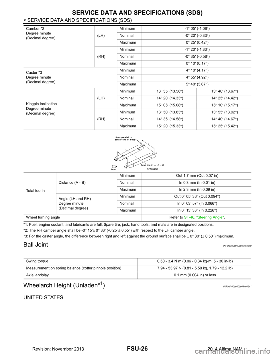
Total toe-in Distance (A - B)
Minimum Out 1.7 mm (Out 0.07 in)
Nominal In 0.3 mm (In 0.01 in)
Maximum In 2.3 mm (In 0.09 in)
Angle (LH and RH)
Degree minute
(Decimal degree) Minimum Out 0
° 05 ′ 38 ″ (Out 0.094 °)
Nominal In 0 ° 03 ′ 57 ″ (In 0.066 °)
Maximum In 0 ° 13 ′ 33 ″ (In 0.226 °)
Wheel turning angle Refer to ST-46, "Steering Angle"
.
SFA234AC
Swing torque 0.50 - 3.4 N·m (0 .06 - 0.34 kg-m, 5 - 30 in-lb)
Measurement on spring balance (cotter pinhole position) 7.94 - 53.97 N (0.81 - 5.50 kg, 1.79 - 12.2 lb)
Axial endplay 0.1 mm (0.004 in) or less
Revision: November 20132014 Altima NAM
Page 2553 of 4801
IDENTIFICATION INFORMATIONGI-25
< VEHICLE INFORMATION >
C
D E
F
G H
I
J
K L
M B
GI
N
O P
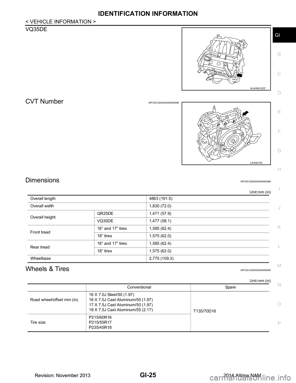
VQ35DE
CVT NumberINFOID:0000000009462988
DimensionsINFOID:0000000009462989
Unit:mm (in)
Wheels & TiresINFOID:0000000009462990
Unit:mm (in)
ALAIA0013ZZ
LAIA0074E
Overall length 4863 (191.5)
Overall width 1,830 (72.0)
Overall height QR25DE 1,471 (57.9)
VQ35DE 1,477 (58.1)
Front tread 16” and 17” tires 1,585 (62.4)
18” tires 1,575 (62.0)
Rear tread 16” and 17” tires 1,585 (62.4)
18” tires 1,575 (62.0)
Wheelbase 2,775 (109.3)
Conventional Spare
Road wheel/offset mm (in) 16 X 7.0J Steel/50 (1.97)
16 X 7.0J Cast Aluminum/50 (1.97)
17 X 7.5J Cast Aluminum/50 (1.97)
18 X 7.5J Cast Aluminum/55 (2.17) T135/70D16
Tire size P215/60R16
P215/55R17
P235/45R18
Revision: November 20132014 Altima NAMRevision: November 20132014 Altima NAM
Page 3706 of 4801
GLASS LIDRF-41
< REMOVAL AND INSTALLATION >
C
D E
F
G H
I
J
L
M A
B
RF
N
O P
REMOVAL AND INSTALLATION
GLASS LID
Removal and InstallationINFOID:0000000009461324
REMOVAL
CAUTION:
• After installing glass li d, check gap/height adjustments and oper ation to make sure there is no mal-
function.
• Handle glass lid with care to prevent damage.
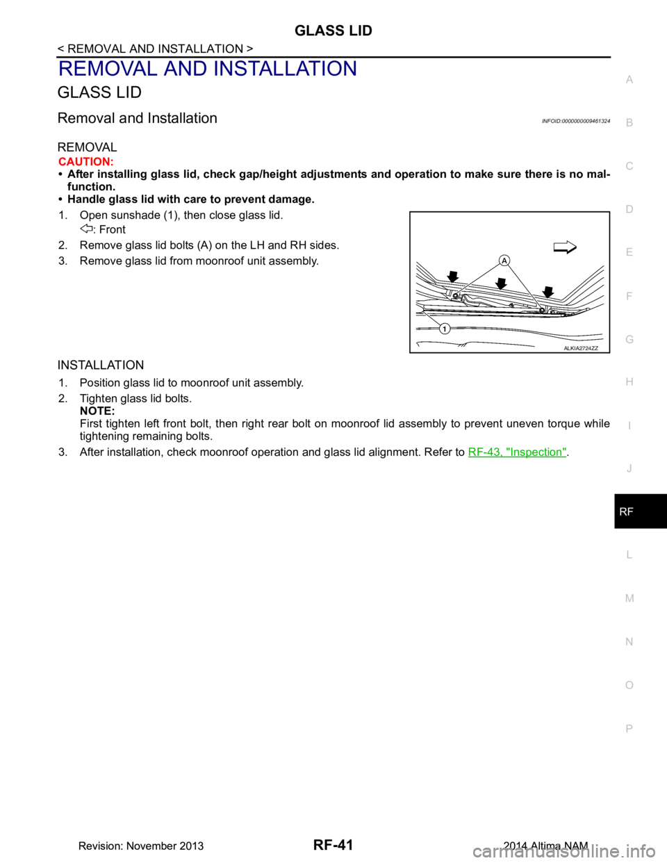
1. Open sunshade (1), then close glass lid. : Front
2. Remove glass lid bolts (A) on the LH and RH sides.
3. Remove glass lid from moonroof unit assembly.
INSTALLATION
1. Position glass lid to moonroof unit assembly.
2. Tighten glass lid bolts. NOTE:
First tighten left front bolt, then right rear bolt on moonroof lid assembly to prevent uneven torque while
tightening remaining bolts.
3. After installation, check moonroof operation and glass lid alignment. Refer to RF-43, "Inspection"
.
ALKIA2724ZZ
Revision: November 20132014 Altima NAMRevision: November 20132014 Altima NAM
Page 3710 of 4801
MOONROOF UNIT ASSEMBLYRF-45
< REMOVAL AND INSTALLATION >
C
D E
F
G H
I
J
L
M A
B
RF
N
O P
Unit: mm (in)
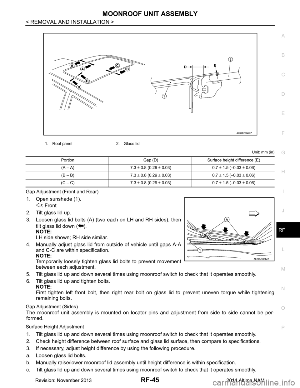
Gap Adjustment (Front and Rear)
1. Open sunshade (1). : Front
2. Tilt glass lid up.
3. Loosen glass lid bolts (A) (two each on LH and RH sides), then tilt glass lid down ( ).
NOTE:
LH side shown; RH side similar.
4. Manually adjust glass lid from outside of vehicle until gaps A-A
and C-C are within specification.
NOTE:
Temporarily loosely tighten glass lid bolts to prevent movement
between each adjustment.
5. Tilt glass lid up and down several times using moonr oof switch to check that it operates smoothly.
6. Tilt glass lid up and tighten bolts. NOTE:
First tighten left front bolt, then right rear bolt on glass lid to prevent uneven torque while tightening
remaining bolts.
Gap Adjustment (Sides)
The moonroof unit assembly is mounted on locator pi ns and adjustment from side to side cannot be per-
formed.
Surface Height Adjustment
1. Tilt glass lid up and down several times using moonr oof switch to check that it operates smoothly.
2. Check height difference between roof surface and glas s lid surface, then compare to specifications.
3. If necessary, adjust height difference by using the following procedure.
a. Loosen glass lid bolts.
b. Manually raise/lower moonroof lid assembly until height difference is within specification.
c. Tilt glass lid up and down several times using moonr oof switch to check that it operates smoothly.
1. Roof panel 2. Glass lid
ALKIA2280ZZ
Portion Gap (D) Surface height difference (E)
(A – A) 7.3 ± 0.8 (0.29 ± 0.03) 0.7 ± 1.5 (–0.03 ± 0.06)
(B – B) 7.3 ± 0.8 (0.29 ± 0.03) 0.7 ± 1.5 (–0.03 ± 0.06)
(C – C) 7.3 ± 0.8 (0.29 ± 0.03) 0.7 ± 1.5 (–0.03 ± 0.06)
ALKIA2724ZZ
Revision: November 20132014 Altima NAMRevision: November 20132014 Altima NAM