Page 4702 of 4801
ID REGISTRATION PROCEDUREWT-27
< BASIC INSPECTION >
C
D
F
G H
I
J
K L
M A
B
WT
N
O P
2. Turn the ignition switch ON.
3. Using CONSULT, select “WORK SUPPORT” in BC M (AIR PRESSURE MONITOR). Then, select “ID
REGIST.”
4. Select “Start” on “ID REGIST” screen.
5. Drive the vehicle at a speed greater than 40 km/h (25 MPH) for 3 minutes or more.
6. After ID registration for all wheels is complete, pr ess “End” on the CONSULT to finish ID registration.
7. Adjust the tire pressures for all tires to the recommended value. Refer to WT-60, "Tire"
.
8. Test drive the vehicle to ensure that the TPMS lamp is OFF and no warning messages are present.
Rear RH 200 (2.0, 29)
Rear LH 180 (1.8, 26)
ID registration position CONSULT Front LH “Yet (red)”↓
“Done (green)”
Front RH
Rear RH Rear LH
Tire position
Tire pressure kPa (kg/cm
2, psi)
Revision: November 20132014 Altima NAMRevision: November 20132014 Altima NAM
Page 4727 of 4801

WT-52
< SYMPTOM DIAGNOSIS >
NOISE, VIBRATION AND HARSHNESS (NVH) TROUBLESHOOTING
NOISE, VIBRATION AND HARSHNESS (NVH) TROUBLESHOOTING
NVH Troubleshooting ChartINFOID:0000000009464519
Use chart below to help you find the cause of the symp tom. If necessary, repair or replace these parts.
×: ApplicableReference page
WT-55, "Adjustment"WT-53, "Inspection"WT-55, "Adjustment"
WT-60, "Tire"
—
—
—
WT-60, "Tire"
FAX-5, "NVH Troubleshooting Chart"
,
FSU-6, "NVH Troubleshooting Chart"
RAX-4, "NVH Troubleshooting Chart"
,
RSU-4, "NVH Troubleshooting Chart"
Refer to TIRES in this chart.
Refer to ROAD WHEEL in this chart.
FAX-5, "NVH Troubleshooting Chart"
BR-6, "NVH Troubleshooting Chart"ST-29, "NVH Troubleshooting Chart"
Possible cause and SUSPECTED
PA R T S
Improper installation, looseness
Out-of-round
Imbalance
Incorrect tire pressure
Uneven tire wear
Deformation or damage
Non-uniformity
Incorrect tire size
FRONT AXLE AND FRONT SUSPENSION
REAR AXLE AND REAR SUSPENSION
TIRES
ROAD WHEELS
DRIVE SHAFT
BRAKE
STEERING
Symptom TIRESNoise
××××××× × × ××××
Shake ×××××× × × × ××××
Vibration ××××××
Shimmy ×××××××× × × × ××
Shudder ×××××× × × × × ××
Poor quality ride
or handling ×××××× × × ××
ROAD
WHEEL Noise
×× × × × × × × × ×
Shake ×× × × × × × × × ×
Shimmy, Shud-
der ×××× ×××××
Poor quality ride
or handling ×× × × × × ×
Revision: November 20132014 Altima NAMRevision: November 20132014 Altima NAM
Page 4728 of 4801

ROAD WHEELWT-53
< PERIODIC MAINTENANCE >
C
D
F
G H
I
J
K L
M A
B
WT
N
O P
PERIODIC MAINTENANCE
ROAD WHEEL
InspectionINFOID:0000000009464520
ALUMINUM WHEEL
1. Check tires for wear and improper inflation.
2. Check wheels for deformation, cracks and other damage. If deformed, remove wheel and check wheel
runout.
3. Remove tire from aluminum wheel and mount wheel on a tire balance machine.
CAUTION:
DO NOT use center hole cone-type clamping machines to
hold the wheel assembly during tire removal/installation or
balancing. Damage to the wheel finish, cladding or chrome
may occur. Use only rim-type or universal lug-type clamp-
ing machines to hold the wheel assembly.
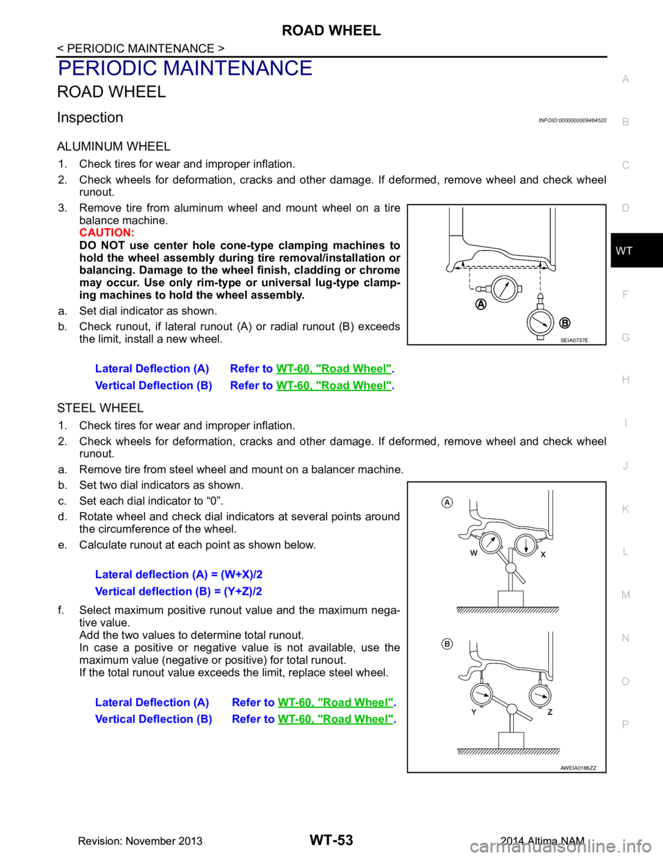
a. Set dial indicator as shown.
b. Check runout, if lateral runout (A) or radial runout (B) exceeds
the limit, install a new wheel.
STEEL WHEEL
1. Check tires for wear and improper inflation.
2. Check wheels for deformation, cracks and other damage. If deformed, remove wheel and check wheel
runout.
a. Remove tire from steel wheel and mount on a balancer machine.
b. Set two dial indicators as shown.
c. Set each dial indicator to “0”.
d. Rotate wheel and check dial indicators at several points around the circumference of the wheel.
e. Calculate runout at each point as shown below.
f. Select maximum positive runout value and the maximum nega- tive value.
Add the two values to determine total runout.
In case a positive or negative value is not available, use the
maximum value (negative or positive) for total runout.
If the total runout value exceeds the limit, replace steel wheel.
Lateral Deflection (A) Refer to
WT-60, "Road Wheel"
.
Vertical Deflection (B) Refer to WT-60, "Road Wheel"
.
SEIA0737E
Lateral deflection (A) = (W+X)/2
Vertical deflection (B) = (Y+Z)/2
Lateral Deflection (A) Refer to WT-60, "Road Wheel"
.
Vertical Deflection (B) Refer to WT-60, "Road Wheel"
.
AWEIA0186ZZ
Revision: November 20132014 Altima NAMRevision: November 20132014 Altima NAM
Page 4731 of 4801

WT-56
< REMOVAL AND INSTALLATION >
ROAD WHEEL TIRE ASSEMBLY
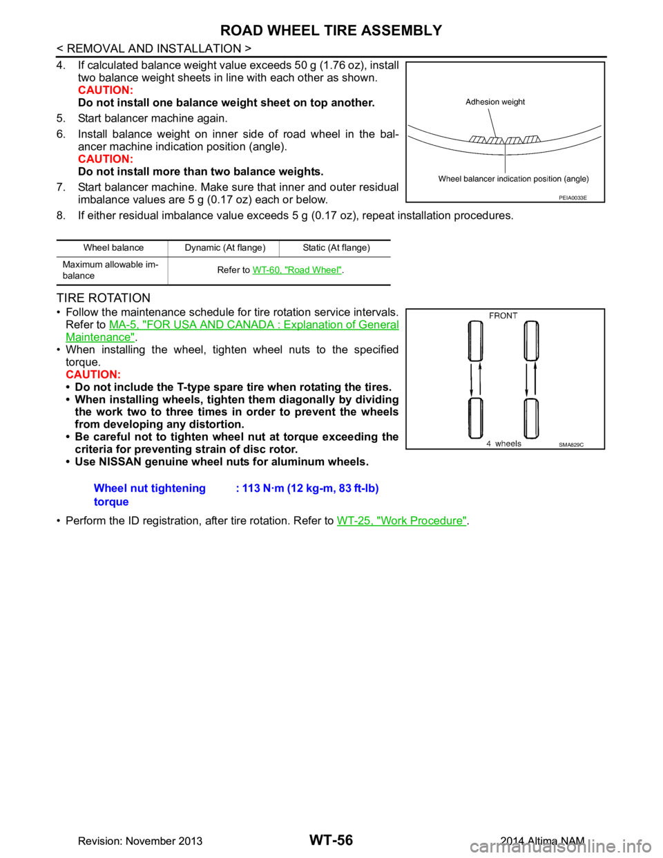
4. If calculated balance weight value exceeds 50 g (1.76 oz), installtwo balance weight sheets in line with each other as shown.
CAUTION:
Do not install one balance weight sheet on top another.
5. Start balancer machine again.
6. Install balance weight on inner side of road wheel in the bal- ancer machine indication position (angle).
CAUTION:
Do not install more than two balance weights.
7. Start balancer machine. Make sure that inner and outer residual imbalance values are 5 g (0.17 oz) each or below.
8. If either residual imbalance value exceeds 5 g (0.17 oz), repeat installation procedures.
TIRE ROTATION
• Follow the maintenance schedule for tire rotation service intervals.
Refer to MA-5, "FOR USA AND CANADA : Explanation of General
Maintenance".
• When installing the wheel, tighten wheel nuts to the specified torque.
CAUTION:
• Do not include the T-type spare tire when rotating the tires.
• When installing wheels, tighten them diagonally by dividing
the work two to three times in order to prevent the wheels
from developing any distortion.
• Be careful not to tighten wheel nut at torque exceeding the criteria for preventing strain of disc rotor.
• Use NISSAN genuine wheel nuts for aluminum wheels.
• Perform the ID registration, after tire rotation. Refer to WT-25, "Work Procedure"
.
Wheel balance Dynamic (At flange) Static (At flange)
Maximum allowable im-
balance Refer to
WT-60, "Road Wheel"
.
PEIA0033E
Wheel nut tightening
torque : 113 N·m (12 kg-m, 83 ft-lb)
SMA829C
Revision: November 20132014 Altima NAMRevision: November 20132014 Altima NAM