2014 NISSAN TEANA tires
[x] Cancel search: tiresPage 4139 of 4801
ST-36
< REMOVAL AND INSTALLATION >
STEERING GEAR AND LINKAGE
STEERING GEAR AND LINKAGE
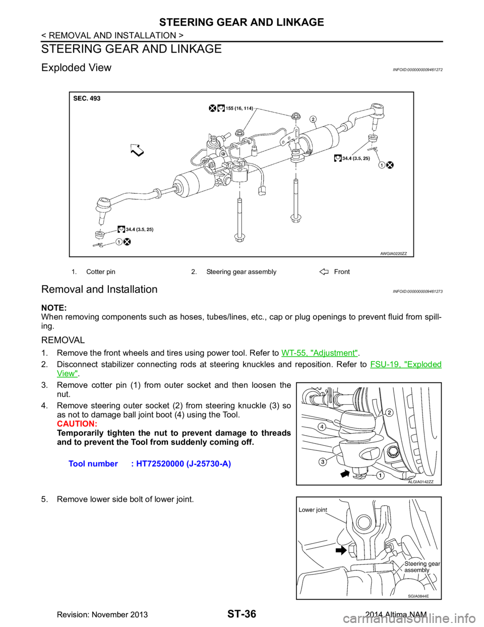
Exploded ViewINFOID:0000000009461272
Removal and InstallationINFOID:0000000009461273
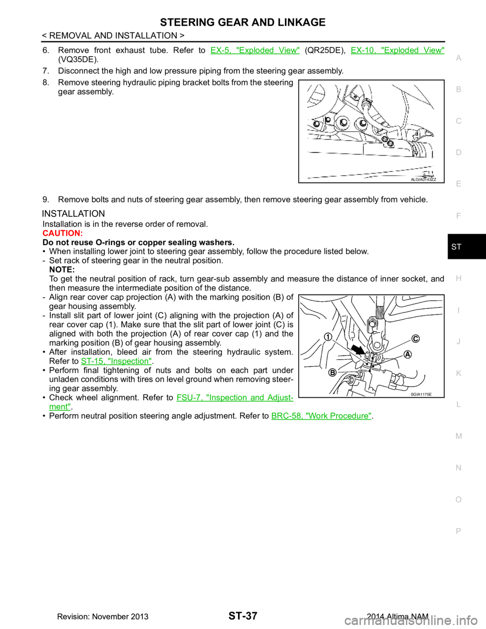
NOTE:
When removing components such as hoses, tubes/lines, etc. , cap or plug openings to prevent fluid from spill-
ing.
REMOVAL
1. Remove the front wheels and tires using power tool. Refer to WT-55, "Adjustment".
2. Disconnect stabilizer connecting rods at st eering knuckles and reposition. Refer to FSU-19, "Exploded
View".
3. Remove cotter pin (1) from outer socket and then loosen the nut.
4. Remove steering outer socket (2) from steering knuckle (3) so as not to damage ball joint boot (4) using the Tool.
CAUTION:
Temporarily tighten the nut to prevent damage to threads
and to prevent the Tool fr om suddenly coming off.
5. Remove lower side bolt of lower joint.
1. Cotter pin 2. Steering gear assembly Front
AWGIA0220ZZ
Tool number : HT72520000 (J-25730-A)
ALGIA0142ZZ
SGIA0844E
Revision: November 20132014 Altima NAMRevision: November 20132014 Altima NAM
Page 4140 of 4801
STEERING GEAR AND LINKAGEST-37
< REMOVAL AND INSTALLATION >
C
D E
F
H I
J
K L
M A
B
ST
N
O P
6. Remove front exhaust tube. Refer to EX-5, "Exploded View" (QR25DE), EX-10, "Exploded View"
(VQ35DE).
7. Disconnect the high and low pressure piping from the steering gear assembly.
8. Remove steering hydraulic piping bracket bolts from the steering gear assembly.
9. Remove bolts and nuts of steering gear assembly, then remove steering gear assembly from vehicle.
INSTALLATION
Installation is in the reverse order of removal.
CAUTION:
Do not reuse O-rings or copper sealing washers.
• When installing lower joint to steering gear assembly, follow the procedure listed below.
- Set rack of steering gear in the neutral position. NOTE:
To get the neutral position of rack, turn gear-sub a ssembly and measure the distance of inner socket, and
then measure the intermediat e position of the distance.
- Align rear cover cap projection (A) with the marking position (B) of
gear housing assembly.
- Install slit part of lower joint (C) aligning with the projection (A) of
rear cover cap (1). Make sure that the slit part of lower joint (C) is
aligned with both the projection (A) of rear cover cap (1) and the
marking position (B) of gear housing assembly.
• After installation, bleed air from the steering hydraulic system. Refer to ST-15, "Inspection"
.
• Perform final tightening of nuts and bolts on each part under
unladen conditions with tires on level ground when removing steer-
ing gear assembly.
• Check wheel alignment. Refer to FSU-7, "Inspection and Adjust-
ment".
• Perform neutral position steering angle adjustment. Refer to BRC-58, "Work Procedure"
.
ALGIA0143ZZ
SGIA1175E
Revision: November 20132014 Altima NAMRevision: November 20132014 Altima NAM
Page 4301 of 4801
![NISSAN TEANA 2014 Service Manual
TM-86
< BASIC INSPECTION >[CVT: RE0F10D]
STALL TEST
STALL TEST
Work ProcedureINFOID:0000000009464016
INSPECTION
1. Check the engine oil level. Replenish if necessary. Refer to
LU-9, "Inspection".
2. NISSAN TEANA 2014 Service Manual
TM-86
< BASIC INSPECTION >[CVT: RE0F10D]
STALL TEST
STALL TEST
Work ProcedureINFOID:0000000009464016
INSPECTION
1. Check the engine oil level. Replenish if necessary. Refer to
LU-9, "Inspection".
2.](/manual-img/5/57390/w960_57390-4300.png)
TM-86
< BASIC INSPECTION >[CVT: RE0F10D]
STALL TEST
STALL TEST
Work ProcedureINFOID:0000000009464016
INSPECTION
1. Check the engine oil level. Replenish if necessary. Refer to
LU-9, "Inspection".
2. Check for leak of the CVT fluid. Refer to TM-178, "Inspection"
.
3. Drive for about 10 minutes to warm up the vehicle so that the CVT fluid temperature is 50 to 80°C (122 to
176 °F).
4. Be sure to apply the parking brake and block the tires.
5. Start the engine, depress the brake pedal and put the selector lever to the D position.
6. While depressing the brake pedal, depress the accelerator pedal gradually.
7. Read the stall speed quickly. Then, release your foot from the accelerator pedal quickly. CAUTION:
Do not depress the accelerator pedal for 5 seconds or more during the test.
8. Place the selector lever in the N position.
9. Cool the CVT fluid. CAUTION:
Run the engine with the idle speed for at least 1 minute.
10. Put the selector lever to the R position and perform Step 6 to Step 9 again.
NARROWING-DOWN MALFUNCTIONING PARTS
O: Within the stall speed standard value.
H: Stall speed is higher than the standard value.
L: Stall speed is lower than the standard value.
Stall speed : Refer to TM-212, "Stall Speed".
Selector lever position
Possible cause
DR
Stal l s pe ed HO•Forward clutch
O H • Reverse brake
LL •Engine
• Torque converter one way clutch
HH • Line pressure is low.
• Primary pulley
• Secondary pulley
• Steel belt
Revision: November 20132014 Altima NAMRevision: November 20132014 Altima NAM
Page 4503 of 4801
![NISSAN TEANA 2014 Service Manual
TM-288
< BASIC INSPECTION >[CVT: RE0F10E]
STALL TEST
STALL TEST
Work ProcedureINFOID:0000000009464233
INSPECTION
1. Check the engine oil level. Replenish if necessary. Refer to
LU-25, "Inspection".
NISSAN TEANA 2014 Service Manual
TM-288
< BASIC INSPECTION >[CVT: RE0F10E]
STALL TEST
STALL TEST
Work ProcedureINFOID:0000000009464233
INSPECTION
1. Check the engine oil level. Replenish if necessary. Refer to
LU-25, "Inspection".](/manual-img/5/57390/w960_57390-4502.png)
TM-288
< BASIC INSPECTION >[CVT: RE0F10E]
STALL TEST
STALL TEST
Work ProcedureINFOID:0000000009464233
INSPECTION
1. Check the engine oil level. Replenish if necessary. Refer to
LU-25, "Inspection".
2. Check for leak of the CVT fluid. Refer to TM-377, "Inspection"
.
3. Drive for about 10 minutes to warm up the vehicle so that the CVT fluid temperature is 50 to 80°C (122 to
176 °F).
4. Be sure to apply the parking brake and block the tires.
5. Start the engine, depress the brake pedal and sh ift the selector lever to “D” position.
6. While depressing the brake pedal, depress the accelerator pedal gradually.
7. Read the stall speed quickly and release your foot from the accelerator pedal quickly. CAUTION:
Do not depress the accelerator pedal for 5 seconds or more during the test.
8. Shift the selector lever to “N” position.
9. Cool the CVT fluid. CAUTION:
Run the engine with the idle speed for at least 1 minute.
10. Put the selector lever to the R position and perform Step 6 to Step 9 again.
NARROWING-DOWN MALFUNCTIONING PARTS
O: Within the stall speed standard value.
H: Stall speed is higher than the standard value.
L: Stall speed is lower than the standard value.
Stall speed : Refer to TM-413, "Stall Speed".
Selector lever position
Possible cause
DR
Stal l s pe ed HO•Forward clutch
O H • Reverse brake
LL •Engine
• Torque converter one way clutch
HH • Line pressure is low.
• Primary pulley
• Secondary pulley
• Chain belt
Revision: November 20132014 Altima NAMRevision: November 20132014 Altima NAM
Page 4676 of 4801

WT-1
SUSPENSION
C
D
F
G H
I
J
K L
M
SECTION WT
A
B
WT
N
O PCONTENTS
ROAD WHEELS & TIRES
PRECAUTION ................ ...............................3
PRECAUTIONS .............................................. .....3
Precaution for Supplemental Restraint System
(SRS) "AIR BAG" and "SEAT BELT PRE-TEN-
SIONER" ............................................................. ......
3
Service Notice and Precautions for TPMS ................3
Precaution for Road Wheel .......................................4
PREPARATION ............................................5
PREPARATION .............................................. .....5
Special Service Tool ........................................... ......5
Commercial Service Tool ..........................................5
SYSTEM DESCRIPTION ..............................6
COMPONENT PARTS ................................... .....6
Component Parts Location .................................. ......6
Component Description .............................................6
BCM ..........................................................................6
Transmitter ................................................................7
Remote Keyless Entry Receiver ...............................7
Outside Key Antennas ..............................................7
Combination Meter ....................................................7
SYSTEM ..............................................................8
System Diagram .................................................. ......8
System Description ...................................................9
Easy Fill Tire Alert Function ......................................9
DIAGNOSIS SYSTEM (BCM) ............................10
COMMON ITEM ..................................................... ....10
COMMON ITEM : CONSULT Function (BCM -
COMMON ITEM) ................................................. ....
10
AIR PRESSURE MONITOR ......................................11
AIR PRESSURE MONITOR : CONSULT Function
(BCM-AIR PRESSURE MO NITOR) ........................
11
ECU DIAGNOSIS INFORMATION ........... ...13
BCM ...................................................................13
List of ECU Reference ......................................... ....13
WIRING DIAGRAM ......................................14
TIRE PRESSURE MONITORING SYSTEM ......14
Wiring Diagram - With Individual Tire Pressure
Display ................................................................. ....
14
Wiring Diagram - Without Individual Tire Pressure
Display ................................................................. ....
20
BASIC INSPECTION ...................................24
DIAGNOSIS AND REPAIR WORK FLOW .......24
Work Flow ............................................................ ....24
ID REGISTRATION PROCEDURE ...................25
Description ...............................................................25
Work Procedure .......................................................25
DTC/CIRCUIT DIAGNOSIS .........................28
C1704, C1705, C1706, C1707 LOW TIRE
PRESSURE .......................................................
28
DTC Logic ............................................................ ....28
Diagnosis Procedure ...............................................28
C1708, C1709, C1710, C1711 TRANSMITTER
(NO DATA) ........................................................
30
DTC Logic ............................................................ ....30
Diagnosis Procedure ...............................................30
C1712, C1713, C1714, C1715 TRANSMITTER
(CHECKSUM) ....................................................
33
DTC Logic ............................................................ ....33
Diagnosis Procedure ...............................................33
C1716, C1717, C1718, C1719 TRANSMITTER
(PRESSURE DATA) ..........................................
35
DTC Logic ............................................................ ....35
Diagnosis Procedure ...............................................35
Revision: November 20132014 Altima NAMRevision: November 20132014 Altima NAM
Page 4678 of 4801
PRECAUTIONSWT-3
< PRECAUTION >
C
D
F
G H
I
J
K L
M A
B
WT
N
O P
PRECAUTION
PRECAUTIONS
Precaution for Supplemental Restraint System (SRS) "AIR BAG" and "SEAT BELT
PRE-TENSIONER"
INFOID:0000000009951708
The Supplemental Restraint System such as “A IR BAG” and “SEAT BELT PRE-TENSIONER”, used along
with a front seat belt, helps to reduce the risk or severi ty of injury to the driver and front passenger for certain
types of collision. Information necessary to service t he system safely is included in the SR and SB section of
this Service Manual.
WARNING:
• To avoid rendering the SRS inoper ative, which could increase the risk of personal injury or death in
the event of a collision which would result in air bag inflation, all maintenance must be performed by
an authorized NISSAN/INFINITI dealer.
• Improper maintenance, including in correct removal and installation of the SRS, can lead to personal
injury caused by unintentional act ivation of the system. For removal of Spiral Cable and Air Bag
Module, see the SR section.
• Do not use electrical test equipm ent on any circuit related to the SRS unless instructed to in this
Service Manual. SRS wiring harnesses can be identi fied by yellow and/or orange harnesses or har-
ness connectors.
PRECAUTIONS WHEN USING POWER TOOLS (AIR OR ELECTRIC) AND HAMMERS
WARNING:
• When working near the Airbag Diagnosis Sensor Un it or other Airbag System sensors with the Igni-
tion ON or engine running, DO NOT use air or el ectric power tools or strike near the sensor(s) with a
hammer. Heavy vibration could activate the sensor( s) and deploy the air bag(s), possibly causing
serious injury.
• When using air or electric power tools or hammers , always switch the Ignition OFF, disconnect the
battery and wait at least three mi nutes before performing any service.
Service Notice and Precautions for TPMSINFOID:0000000009464472
WARNING:
Radio waves could adversely affect electrical medi cal equipment. Those who use a pacemaker should
contact the electrical medical equipment manu facturer for possible influences before use.
• Low tire pressure warning lamp blinks for 1 minute, then turns ON when any malfunction occurs except low
tire pressure. Erase the self-diagnosis memories for Tire Pressure Monitoring System (TPMS), or register
the ID to turn low tire pressure warning lamp OFF. For ID registration, refer to WT-25, "Work Procedure"
.
• ID registration is required when replacing or rotating wheels, replacing tire pressure sensor or BCM. Refer to WT-25, "Work Procedure"
.
• For easy fill tire alert function, refer to the following. WT-9, "Easy Fill Tire Alert Function"
- When inflating the tires, park the vehicle in the safe area and ensure the safety of the working area.
- Read and understand the easy fill tire alert function prior to use.
- Inflate the tires one at a time.
- If there is no response for approximately 15 seconds or mo re after inflating the tires, cancel the use of the
easy fill tire alert function or move the vehicle approximately 1 m (3.2 ft) backward or forward to try again.
The air filler pressure may be weak or out of service area.
- Despite the high-precision TPMS pressure sensor, an i ndicated value may differ from that of the pressure
gauge.
- Air pressure is measured rather high due to the rise in tire air temperature after driving.
- If TPMS is malfunctioning, the easy fill tire alert is unusable.
• Replace grommet seal, valve core and valve cap of tire pressure sensor in TPMS when replacing each tire
by reaching the wear limit. Refer to WT-57, "Exploded View"
.
• Because the tire pressure sensor conforms to No rth America radio law, the following items must be
observed.
- The sensor may be used only in North America.
- It may not be used in any method other than the specified method.
- It must not be disassembled or modified.
Revision: November 20132014 Altima NAMRevision: November 20132014 Altima NAM
Page 4700 of 4801
ID REGISTRATION PROCEDUREWT-25
< BASIC INSPECTION >
C
D
F
G H
I
J
K L
M A
B
WT
N
O P
ID REGISTRATION PROCEDURE
DescriptionINFOID:0000000009464492
This procedure must be performed:
• after replacement of a transmitter or BCM (with individual tire pressure display).
• after replacement of a transmitter, BCM or rotation of the wheels (without individual tire pressure display).
Work ProcedureINFOID:0000000009464493
TPMS ID registration can be performed using one of the following procedures:
• Transmitter Activation tool (J-45295-A) with CONSULT (preferred method)
• Signal Tech II tool (J-50190) with CONSULT (preferred method)
• Signal Tech II tool (J-50190) without CONSULT
• CONSULT only
TPMS REGISTRATION WITH TRANSMI TTER ACTIVATION TOOL (J-45295-A)
With CONSULT
1. Turn the ignition switch ON.
2. Using CONSULT, select “WORK SUPPORT” in BC M (AIR PRESSURE MONITOR). Then, select “ID
REGIST.”
3. Select “Start” on “ID REGIST” screen.
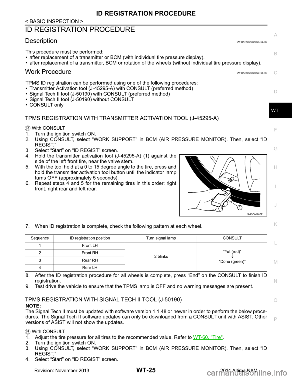
4. Hold the transmitter activation tool (J-45295-A) (1) against the side of the left front tire, near the valve stem.
5. With the tool held at a 0 to 15 degree angle to the tire, press and
hold the transmitter activation tool button until the indicator lamp
turns OFF (approximately 5 seconds).
6. Repeat steps 4 and 5 for the remaining tires in this order: right
front, right rear and left rear.
7. When ID registration is complete, check the following pattern at each wheel.
8. After the ID registration procedure for all wheels is complete, press “End” on the CONSULT to finish ID registration.
9. Test drive the vehicle to ensure that the TPMS lamp is OFF and no warning messages are present.
TPMS REGISTRATION WITH SIGNAL TECH II TOOL (J-50190)
NOTE:
The Signal Tech II must be updated with software version 1.1.48 or newer in order to perform the below proce-
dures. The Signal Tech II software updates can onl y be downloaded from a CONSULT unit with ASIST. Other
versions of ASIST will not show the updates.
With CONSULT
1. Adjust the tire pressure for all tires to the recommended value. Refer to WT-60, "Tire".
2. Turn the ignition switch ON.
3. Using CONSULT, select “WORK SUPPORT” in BC M (AIR PRESSURE MONITOR). Then, select “ID
REGIST.”
4. Select “Start” on “ID REGIST” screen.
NNEIC0020ZZ
Sequence ID registration position Turn signal lamp CONSULT
1 Front LH
2 blinks“Yet (red)”
↓
“Done (green)”
2Front RH
3 Rear RH
4 Rear LH
Revision: November 20132014 Altima NAMRevision: November 20132014 Altima NAM
Page 4701 of 4801
WT-26
< BASIC INSPECTION >
ID REGISTRATION PROCEDURE
5. Turn on the Signal Tech II tool (J-50190).
6. Hold the Signal Tech II against the side of the left front tire, near the valve stem.
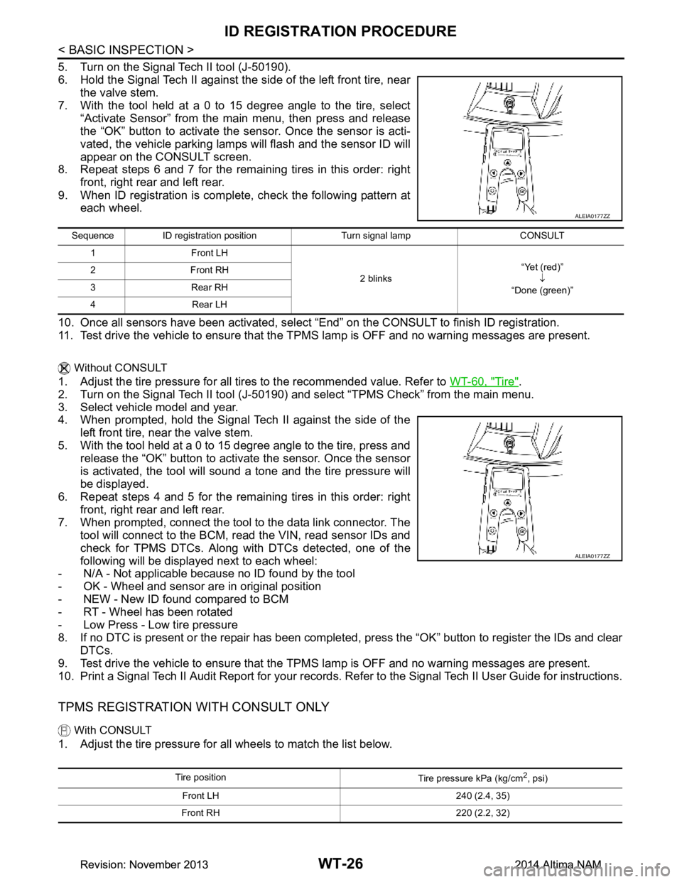
7. With the tool held at a 0 to 15 degree angle to the tire, select
“Activate Sensor” from the main menu, then press and release
the “OK” button to activate the s ensor. Once the sensor is acti-
vated, the vehicle parking lamps will flash and the sensor ID will
appear on the CONSULT screen.
8. Repeat steps 6 and 7 for the remaining tires in this order: right
front, right rear and left rear.
9. When ID registration is complete, check the following pattern at each wheel.
10. Once all sensors have been activated, select “End” on the CONSULT to finish ID registration.
11. Test drive the vehicle to ensure that the TPMS lamp is OFF and no warning messages are present.
Without CONSULT
1. Adjust the tire pressure for all tires to the recommended value. Refer to WT-60, "Tire".
2. Turn on the Signal Tech II tool (J-50190) and select “TPMS Check” from the main menu.
3. Select vehicle model and year.
4. When prompted, hold the Signal Tech II against the side of the
left front tire, near the valve stem.
5. With the tool held at a 0 to 15 degree angle to the tire, press and release the “OK” button to activate the sensor. Once the sensor
is activated, the tool will sound a tone and the tire pressure will
be displayed.
6. Repeat steps 4 and 5 for the remaining tires in this order: right
front, right rear and left rear.
7. When prompted, connect the tool to the data link connector. The tool will connect to the BCM, read the VIN, read sensor IDs and
check for TPMS DTCs. Along wit h DTCs detected, one of the
following will be displayed next to each wheel:
- N/A - Not applicable because no ID found by the tool
- OK - Wheel and sensor are in original position
- NEW - New ID found compared to BCM
- RT - Wheel has been rotated
- Low Press - Low tire pressure
8. If no DTC is present or the repair has been complet ed, press the “OK” button to register the IDs and clear
DTCs.
9. Test drive the vehicle to ensure that the TPMS lamp is OFF and no warning messages are present.
10. Print a Signal Tech II Audit Report for your records. Re fer to the Signal Tech II User Guide for instructions.
TPMS REGISTRATION WITH CONSULT ONLY
With CONSULT
1. Adjust the tire pressure for all wheels to match the list below.
ALEIA0177ZZ
Sequence ID registration position Turn signal lamp CONSULT
1Front LH
2 blinks“Yet (red)”
↓
“Done (green)”
2Front RH
3Rear RH
4Rear LH
ALEIA0177ZZ
Tire position Tire pressure kPa (kg/cm2, psi)
Front LH 240 (2.4, 35)
Front RH 220 (2.2, 32)
Revision: November 20132014 Altima NAMRevision: November 20132014 Altima NAM