2014 NISSAN TEANA heating
[x] Cancel search: heatingPage 2640 of 4801

HA-34
< REMOVAL AND INSTALLATION >
COOLER PIPE AND HOSE
COOLER PIPE AND HOSE
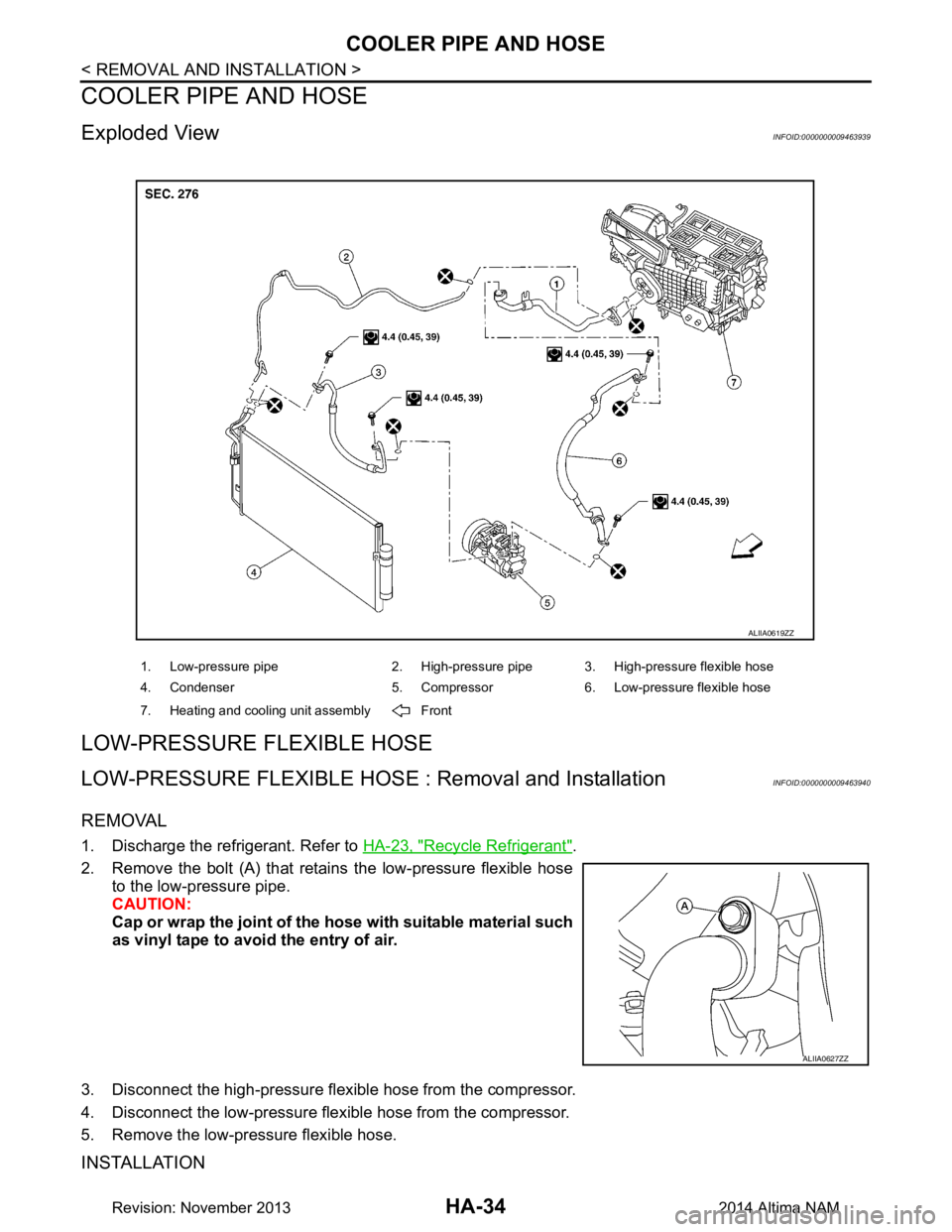
Exploded ViewINFOID:0000000009463939
LOW-PRESSURE FLEXIBLE HOSE
LOW-PRESSURE FLEXIBLE HOSE : Removal and InstallationINFOID:0000000009463940
REMOVAL
1. Discharge the refrigerant. Refer to HA-23, "Recycle Refrigerant".
2. Remove the bolt (A) that retain s the low-pressure flexible hose
to the low-pressure pipe.
CAUTION:
Cap or wrap the joint of the ho se with suitable material such
as vinyl tape to avoid the entry of air.
3. Disconnect the high-pressure flexible hose from the compressor.
4. Disconnect the low-pressure flexible hose from the compressor.
5. Remove the low-pressure flexible hose.
INSTALLATION
1. Low-pressure pipe 2. High-pressure pipe 3. High-pressure flexible hose
4. Condenser 5. Compressor 6. Low-pressure flexible hose
7. Heating and cooling unit assembly Front
ALIIA0619ZZ
ALIIA0627ZZ
Revision: November 20132014 Altima NAM
Page 2646 of 4801

HA-40
< REMOVAL AND INSTALLATION >
HEATING AND COOLING UNIT ASSEMBLY
HEATING AND COOLING UNIT ASSEMBLY
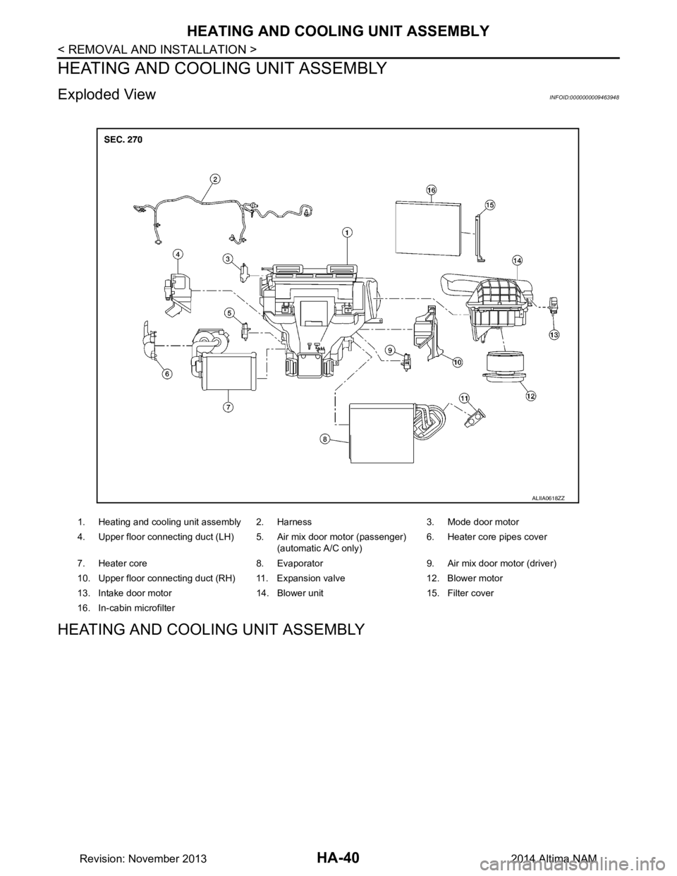
Exploded ViewINFOID:0000000009463948
HEATING AND COOLING UNIT ASSEMBLY
1. Heating and cooling unit assembly 2. Harness 3. Mode door motor
4. Upper floor connecting duct (LH) 5. Air mix door motor (passenger) (automatic A/C only)6. Heater core pipes cover
7. Heater core 8. Evaporator 9. Air mix door motor (driver)
10. Upper floor connecting duct (RH) 11. Expansion valve 12. Blower motor
13. Intake door motor 14. Blower unit 15. Filter cover
16. In-cabin microfilter
ALIIA0618ZZ
Revision: November 20132014 Altima NAM
Page 2647 of 4801

HEATING AND COOLING UNIT ASSEMBLYHA-41
< REMOVAL AND INSTALLATION >
C
D E
F
G H
J
K L
M A
B
HA
N
O P
HEATING AND COOLING UNIT ASSEMB LY : Removal and InstallationINFOID:0000000009463949
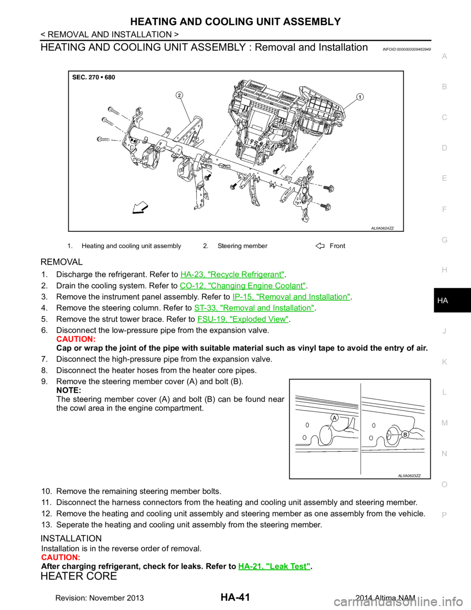
REMOVAL
1. Discharge the refrigerant. Refer to HA-23, "Recycle Refrigerant".
2. Drain the cooling system. Refer to CO-12, "Changing Engine Coolant"
.
3. Remove the instrument panel assembly. Refer to IP-15, "Removal and Installation"
.
4. Remove the steering column. Refer to ST-33, "Removal and Installation"
.
5. Remove the strut tower brace. Refer to FSU-19, "Exploded View"
.
6. Disconnect the low-pressure pipe from the expansion valve. CAUTION:
Cap or wrap the joint of the pipe with suitable ma terial such as vinyl tape to avoid the entry of air.
7. Disconnect the high-pressure pi pe from the expansion valve.
8. Disconnect the heater hoses from the heater core pipes.
9. Remove the steering member cover (A) and bolt (B). NOTE:
The steering member cover (A) and bolt (B) can be found near
the cowl area in the engine compartment.
10. Remove the remaining steering member bolts.
11. Disconnect the harness connectors from the heati ng and cooling unit assembly and steering member.
12. Remove the heating and cooling unit assembly and steering member as one assembly from the vehicle.
13. Seperate the heating and cooling unit assembly from the steering member.
INSTALLATION
Installation is in the reverse order of removal.
CAUTION:
After charging refrigerant, check for leaks. Refer to HA-21, "Leak Test"
.
HEATER CORE
1. Heating and cooling unit assembly 2. Steering member Front
ALIIA0624ZZ
ALIIA0623ZZ
Revision: November 20132014 Altima NAM
Page 2648 of 4801

HA-42
< REMOVAL AND INSTALLATION >
HEATING AND COOLING UNIT ASSEMBLY
HEATER CORE : Removal and Installation
INFOID:0000000009463950
REMOVAL
1. Remove the heating and cooling unit assembly. Refer to HA-41, "HEATING AND COOLING UNIT
ASSEMBLY : Removal and Installation".
2. Remove the heater core pipes cover. Refer to HA-40, "Exploded View"
.
3. Disconnect the harness connector from the blower motor.
4. Remove the heater core.
INSTALLATION
Installation is in the reverse order of removal.
EVAPORATOR
EVAPORATOR : Removal and InstallationINFOID:0000000009463951
REMOVAL
1. Remove the heater core. Refer to HA-42, "HEATER CORE : Removal and Installation".
2. Remove the upper floor connecting duct (RH). Refer to HA-40, "Exploded View"
.
3. Remove the air mix door motor (driver). Refer to HAC-109, "AIR MIX DOOR MOTOR : Removal and
Installation - Air Mix Door Motor (RH)".
4. Remove the air mix door motor (passenger) (if equipped). Refer to HAC-109, "AIR MIX DOOR MOTOR :
Removal and Installation - Air Mix Door Motor (LH)"
5. Disconnect the harness connector from the intake sensor.
6. Remove the evaporator and expansion valve assembly.
INSTALLATION
Installation is in the reverse order of removal.
NOTE:
The evaporator can only be ordered as an assembly with the expansion valve.
EXPANSION VALVE
EXPANSION VALVE : Removal and Installation for Expansion ValveINFOID:0000000009463952
REMOVAL
1. Discharge the refrigerant. Refer to HA-23, "Recycle Refrigerant".
2. Remove the strut tower brace. Refer to FSU-19, "Exploded View"
.
3. Disconnect the low-pressure pipe from the expansion valve.
4. Disconnect the high-pressure pipe from the expansion valve.
5. Remove the expansion valve bolts.
6. Remove the expansion valve.
INSTALLATION
Installation is in the reverse order of removal.
CAUTION:
After charging refrigerant, check for leaks. Refer to HA-21, "Leak Test"
.
Revision: November 20132014 Altima NAM
Page 2651 of 4801

HAC-2
Diagnosis Procedure ..............................................55
U1010 CONTROL UNIT (CAN) .........................56
Description ........................................................... ...56
DTC Logic ...............................................................56
Diagnosis Procedure ..............................................56
B2578, B2579 IN-VEHICLE SENSOR ...............57
DTC Logic ............................................................ ...57
Diagnosis Procedure ..............................................57
Component Inspection ............................................58
B257B, B257C AMBIENT SENSOR .................60
DTC Logic ............................................................ ...60
Diagnosis Procedure ..............................................60
Component Inspection ............................................61
B2581, B2582 INTAKE SENSOR ......................63
DTC Logic ............................................................ ...63
Diagnosis Procedure ..............................................63
Component Inspection ............................................64
B2630, B2631 SUNLOAD SENSOR .................66
DTC Logic ............................................................ ...66
Diagnosis Procedure ..............................................66
Component Inspection ............................................67
B2632, B2633 AIR MIX DOOR MOTOR
(DRIVER SIDE) ............................................... ...
69
DTC Logic ............................................................ ...69
Diagnosis Procedure ..............................................69
B2634, B2635 AIR MIX DOOR MOTOR (PAS-
SENGER SIDE) ............................................... ...
71
DTC Logic ............................................................ ...71
Diagnosis Procedure ..............................................71
B2636, B2637, B2638, B2639, B2654, B2655
MODE DOOR MOTOR ................................... ...
73
DTC Logic ............................................................ ...73
Diagnosis Procedure ..............................................73
B263D, B263E, B263F INTAKE DOOR MO-
TOR ................................................................. ...
75
DTC Logic ............................................................ ...75
Diagnosis Procedure ..............................................75
B27B0 A/C AUTO AMP. ....................................77
DTC Logic ............................................................ ...77
Diagnosis Procedure ..............................................77
POWER SUPPLY AND GROUND CIRCUIT .....78
A/C AUTO AMP. .................................................... ...78
A/C AUTO AMP. : Diagnosis Procedure ................78
AIR MIX DOOR MOTOR (DRIVER SIDE) .............. ...78
AIR MIX DOOR MOTOR (DRIVER SIDE) : Diag-
nosis Procedure ................................................... ...
78
AIR MIX DOOR MOTOR (PASSENGER SIDE) ..... ...79
AIR MIX DOOR MOTOR (PASSENGER SIDE) :
Diagnosis Procedure ............................................ ...
79
MODE DOOR MOTOR ........................................... ...80
MODE DOOR MOTOR : Diagnosis Procedure .......80
INTAKE DOOR MOTOR ........................................ ...81
INTAKE DOOR MOTOR : Diagnosis Procedure ....81
A/C SWITCH ASSEMBLY .........................................82
A/C SWITCH ASSEMBLY : Component Function
Check ................................................................... ...
82
A/C SWITCH ASSEMBLY : Diagnosis Procedure ...83
BLOWER MOTOR .......................................... ...84
Diagnosis Procedure ............................................ ...84
Component Inspection (Blower Motor) ...................85
Component Inspection (Front Blower Motor Re-
lay) ....................................................................... ...
85
MAGNET CLUTCH ............................................87
Component Function Check ................................ ...87
Diagnosis Procedure ...............................................87
A/C SWITCH ASSEMBLY SIGNAL CIRCUIT ...88
Diagnosis Procedure ...............................................88
DOOR MOTOR ..................................................89
Diagnosis Procedure ............................................ ...89
DOOR MOTOR COMMUNICATION CIRCUIT ...91
Diagnosis Procedure ............................................ ...91
ECV (ELECTRICAL CONTROL VALVE) ..........92
Diagnosis Procedure ............................................ ...92
Component Inspection ............................................93
SYMPTOM DIAGNOSIS ............................94
HEATER AND AIR CONDITIONING SYSTEM
CONTROL SYMPTOMS ................................. ...
94
Diagnosis Chart By Symptom .............................. ...94
INSUFFICIENT COOLING .................................96
Description ........................................................... ...96
Diagnosis Procedure ...............................................96
INSUFFICIENT HEATING .................................98
Description ........................................................... ...98
Diagnosis Procedure ...............................................98
COMPRESSOR DOES NOT OPERATE ...........99
Description ........................................................... ...99
Diagnosis Procedure ...............................................99
REMOVAL AND INSTALLATION .............101
A/C SWITCH ASSEMBLY .............................. ..101
Removal and Installation .......................................101
A/C AUTO AMP. ............................................. ..102
Exploded View ..................................................... .102
Removal and Installation .......................................102
Revision: November 20132014 Altima NAMRevision: November 20132014 Altima NAM
Page 2653 of 4801

HAC-4
HEATER AND AIR CONDITIONING SYSTEM
CONTROL SYMPTOMS ................................. .
154
Symptom Table ................................................... ..154
INSUFFICIENT COOLING ...............................155
Component Function Check ................................ ..155
INSUFFICIENT HEATING ...............................157
Component Function Check ................................ ..157
COMPRESSOR DOES NOT OPERATE .........159
Description ........................................................... ..159
Diagnosis Procedure .............................................159
REMOVAL AND INSTALLATION ..............161
FRONT AIR CONTROL .................................. .161
Removal and Installation ..................................... ..161
IN-VEHICLE SENSOR ......................................162
Removal and Installation .......................................162
REFRIGERANT PRESSURE SENSOR ......... ..163
Removal and Installation .......................................163
DOOR MOTOR ............................................... ..164
Exploded View ..................................................... .164
INTAKE DOOR MOTOR ........................................ .165
INTAKE DOOR MOTOR : Removal and Installa-
tion ....................................................................... .
165
MODE DOOR MOTOR ........................................... .165
MODE DOOR MOTOR : Removal and Installation .165
AIR MIX DOOR MOTOR ........................................ .165
AIR MIX DOOR MOTOR : Removal and Installa-
tion ....................................................................... .
165
Revision: November 20132014 Altima NAMRevision: November 20132014 Altima NAM
Page 2659 of 4801
![NISSAN TEANA 2014 Service Manual
HAC-10
< SYSTEM DESCRIPTION >[AUTOMATIC AIR CONDITIONER]
COMPONENT PARTS
Component Description
INFOID:0000000009463092
1. ECM 2. IPDM E/R 3. BCM (view with combination meter removed)
4. A/C auto amp NISSAN TEANA 2014 Service Manual
HAC-10
< SYSTEM DESCRIPTION >[AUTOMATIC AIR CONDITIONER]
COMPONENT PARTS
Component Description
INFOID:0000000009463092
1. ECM 2. IPDM E/R 3. BCM (view with combination meter removed)
4. A/C auto amp](/manual-img/5/57390/w960_57390-2658.png)
HAC-10
< SYSTEM DESCRIPTION >[AUTOMATIC AIR CONDITIONER]
COMPONENT PARTS
Component Description
INFOID:0000000009463092
1. ECM 2. IPDM E/R 3. BCM (view with combination meter removed)
4. A/C auto amp. (view with A/C switch assembly removed) 5. A/C switch assembly 6. A/C Compressor
7. Sunload sensor 8. Refrigerant pressure sensor (view with front bumper fascia removed)9. Ambient sensor
10. Fuse Block (J/B), Front blower motor relay 11. In-vehicle sensor 12. Accessory relay-2 (view with instru-
ment panel removed)
13. Blower motor (view with front A/C as- sembly removed from vehicle) 14. Intake door motor 15. Mode door motor
16. Air mix door motor LH 17. Air mix door motor RH 18. Intake sensor
ALIIA0599ZZ
Component Description
A/C auto amp. A/C auto amp. controls front automatic air conditioning system by inputting and calculating signals
from each sensor and each switch.
A/C Compressor Vaporized refrigerant is drawn into the A/C compressor from the evaporator, where it is compressed
to a high pressure, high temperature vapor. The hot, compressed vapor is then discharged to the con-
denser.
A/C switch assembly The A/C switch assembly controls the operation of the A/C and heating system based on inputs from
the temperature control knob, the mode switches, the blower control dial, the ambient temperature
sensor, the intake sensor, and inputs received from the ECM across the CAN. Diagnosis of the A/C
switch assembly can be performed using the CONSULT. There is no self-diagnostic feature available.
Air mix door motor LH The air mix door controls the mix of hot or cold air that enters the ventilation system. It is controlled
by the A/C auto amp. based on the position of the temperature dial. The air mix door motor LH re-
ceives position commands from the A/C auto amp. and reports actual door position back via an LCU
(Local Control Unit) installed inside the motor. Commands and responses are sent across the LIN (Lo-
cal Interconnect Network) to each motor simultaneously, with each motor having its own unique ad-
dress, thereby only responding to requests sent to its specific address. The LCU reads the door
position from a Position Balanced Resistor (PBR), also part of the motor, and returns that information
to the A/C auto amp. The LCU switches the polarity of the circuits connected to the DC motor to drive
the motor forward or backward as requested by the A/C auto amp. If the air mix door moves to a po-
sition less than 5% or more than 95% of its expected or allowed positions, the A/C auto amp. will set
a DTC.
Revision: November 20132014 Altima NAMRevision: November 20132014 Altima NAM
Page 2698 of 4801
![NISSAN TEANA 2014 Service Manual
OPERATION INSPECTIONHAC-49
< BASIC INSPECTION > [AUTOMATIC AIR CONDITIONER]
C
D E
F
G H
J
K L
M A
B
HAC
N
O P
YES >> GO TO 6.
NO >> Check magnet clutch system. Refer to HAC-87, "Diagnosis Procedu NISSAN TEANA 2014 Service Manual
OPERATION INSPECTIONHAC-49
< BASIC INSPECTION > [AUTOMATIC AIR CONDITIONER]
C
D E
F
G H
J
K L
M A
B
HAC
N
O P
YES >> GO TO 6.
NO >> Check magnet clutch system. Refer to HAC-87, "Diagnosis Procedu](/manual-img/5/57390/w960_57390-2697.png)
OPERATION INSPECTIONHAC-49
< BASIC INSPECTION > [AUTOMATIC AIR CONDITIONER]
C
D E
F
G H
J
K L
M A
B
HAC
N
O P
YES >> GO TO 6.
NO >> Check magnet clutch system. Refer to HAC-87, "Diagnosis Procedure"
.
6.CHECK TEMPERATURE DECREASE
1. Operate the A/C compressor.
2. Operate the temperature control switch (drive r side) and lower the temperature setting to 18°C (60 °F).
3. Check that the cool air blows from the outlets.
Is the inspection result normal?
YES >> GO TO 7.
NO >> Check for insufficient cooling. Refer to HAC-96, "Diagnosis Procedure"
.
7.CHECK TEMPERATURE INCREASE
1. Operate the temperature control switch (drive r side) and raise the temperature setting to 32°C (90 °F) after
warming up the engine.
2. Check that the warm air blows from the outlets.
Is the inspection result normal?
YES >> GO TO 8.
NO >> Check for insufficient heating. Refer to HAC-98, "Diagnosis Procedure"
.
8.CHECK DUAL MODE FUNCTION
1. Press the DUAL mode switch, and then check that “DUAL” is shown on the display.
2. Operate the temperature control switch (driver si de). Check that the discharge air temperature (driver
side) changes.
3. Operate the temperature control switch (passenger side). Check that the discharge air temperature (pas-
senger side) changes.
4. Press the DUAL mode switch, and then check that the temperature setting (driver/passenger) is unified to
the driver side temperature setting.
Is the inspection result normal?
YES >> GO TO 9.
NO >> Refer to HAC-94, "Diagnosis Chart By Symptom"
and perform the appropriate diagnosis.
9.CHECK AUTO MODE
1. Press the AUTO switch, and then check t hat “AUTO” is shown on the display.
2. Operate the temperature control switch (driver side) . Check that the fan speed, outlet air or intake air
changes. The discharge air temperature or fan speed varies depending on the ambient temperature, in-
vehicle temperature, and temperature setting.
Is the inspection result normal?
YES >> Inspection End
NO >> Refer to HAC-94, "Diagnosis Chart By Symptom"
and perform the appropriate diagnosis.
Revision: November 20132014 Altima NAMRevision: November 20132014 Altima NAM