2014 NISSAN TEANA warning
[x] Cancel search: warningPage 3332 of 4801

MWI
THE DOOR OPEN WARNING CONTINUES DISPLAYING, OR DOES NOT DIS-
PLAY
MWI-77
< SYMPTOM DIAGNOSIS >
C
D E
F
G H
I
J
K L
M B
A
O P
THE DOOR OPEN WARN ING CONTINUES DISPLAYING, OR DOES NOT
DISPLAY
DescriptionINFOID:0000000009461748
• The door ajar warning is displayed even though all of the doors and the trunk are closed.
• The door ajar warning is not displayed even though a door or the trunk is ajar.
Diagnosis ProcedureINFOID:0000000009461749
1.CHECK BCM INPUT SIGNAL
Check the BCM input signal. Refer to DLK-100, "Component Function Check"
.
Is the inspection result normal?
YES >> GO TO 2.
NO >> GO TO 3.
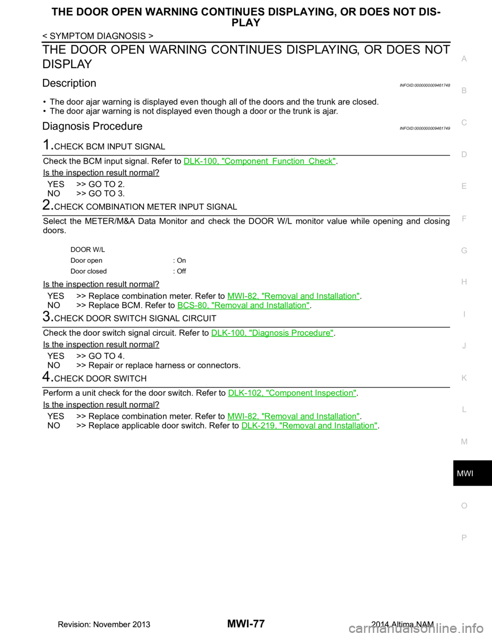
2.CHECK COMBINATION METER INPUT SIGNAL
Select the METER/M&A Data Monitor and check t he DOOR W/L monitor value while opening and closing
doors.
Is the inspection result normal?
YES >> Replace combination meter. Refer to MWI-82, "Removal and Installation".
NO >> Replace BCM. Refer to BCS-80, "Removal and Installation"
.
3.CHECK DOOR SWITCH SIGNAL CIRCUIT
Check the door switch signal circuit. Refer to DLK-100, "Diagnosis Procedure"
.
Is the inspection result normal?
YES >> GO TO 4.
NO >> Repair or replace harness or connectors.
4.CHECK DOOR SWITCH
Perform a unit check for the door switch. Refer to DLK-102, "Component Inspection"
.
Is the inspection result normal?
YES >> Replace combination meter. Refer to MWI-82, "Removal and Installation".
NO >> Replace applicable door switch. Refer to DLK-219, "Removal and Installation"
.
DOOR W/L
Door open : On
Door closed : Off
Revision: November 20132014 Altima NAMRevision: November 20132014 Altima NAM
Page 3333 of 4801

MWI-78
< SYMPTOM DIAGNOSIS >
THE TRUNK OPEN WARNING CONTINUES DISPLAYING, OR DOES NOT DIS-
PLAY
THE TRUNK OPEN WARNING CONTIN UES DISPLAYING, OR DOES NOT
DISPLAY
DescriptionINFOID:0000000009461750
• The trunk ajar warning is displayed continuously even though the trunk lid is closed.
• The trunk ajar warning is not displayed even though the trunk lid is open.
Diagnosis ProcedureINFOID:0000000009461751
1.CHECK BCM INPUT SIGNAL
1. Connect the CONSULT.
2. Check the BCM input signals. Refer to DLK-126, "Component Function Check"
.
Is the inspection result normal?
YES >> GO TO 2.
NO >> GO TO 3.
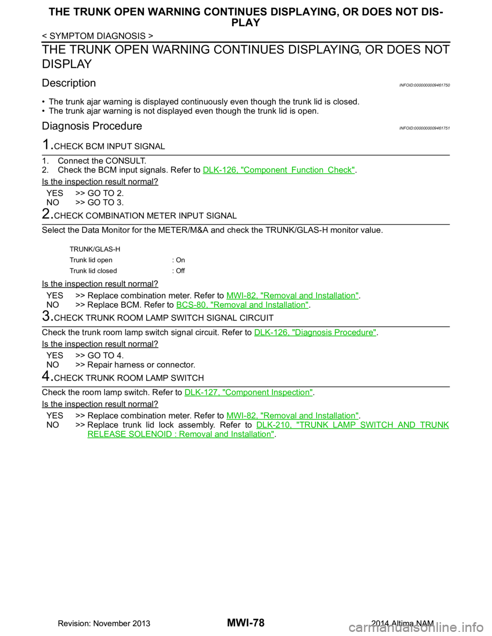
2.CHECK COMBINATION METER INPUT SIGNAL
Select the Data Monitor for the METER/M &A and check the TRUNK/GLAS-H monitor value.
Is the inspection result normal?
YES >> Replace combination meter. Refer to MWI-82, "Removal and Installation".
NO >> Replace BCM. Refer to BCS-80, "Removal and Installation"
.
3.CHECK TRUNK ROOM LAMP SWITCH SIGNAL CIRCUIT
Check the trunk room lamp switch signal circuit. Refer to DLK-126, "Diagnosis Procedure"
.
Is the inspection result normal?
YES >> GO TO 4.
NO >> Repair harness or connector.
4.CHECK TRUNK ROOM LAMP SWITCH
Check the room lamp switch. Refer to DLK-127, "Component Inspection"
.
Is the inspection result normal?
YES >> Replace combination meter. Refer to MWI-82, "Removal and Installation".
NO >> Replace trunk lid lock assembly. Refer to DLK-210, "TRUNK LAMP SWITCH AND TRUNK
RELEASE SOLENOID : Removal and Installation".
TRUNK/GLAS-H
Trunk lid open : On
Trunk lid closed : Off
Revision: November 20132014 Altima NAMRevision: November 20132014 Altima NAM
Page 3340 of 4801

PB-2
< PRECAUTION >
PRECAUTIONS
PRECAUTION
PRECAUTIONS
Precaution for Supplemental Restraint System (SRS) "AIR BAG" and "SEAT BELT
PRE-TENSIONER"
INFOID:0000000009951710
The Supplemental Restraint System such as “A IR BAG” and “SEAT BELT PRE-TENSIONER”, used along
with a front seat belt, helps to reduce the risk or severi ty of injury to the driver and front passenger for certain
types of collision. Information necessary to service the system safely is included in the SR and SB section of
this Service Manual.
WARNING:
• To avoid rendering the SRS inopera tive, which could increase the risk of personal injury or death in
the event of a collision which would result in air bag inflation, all maintenance must be performed by
an authorized NISS AN/INFINITI dealer.
• Improper maintenance, including in correct removal and installation of the SRS, can lead to personal
injury caused by unintent ional activation of the system. For re moval of Spiral Cable and Air Bag
Module, see the SR section.
• Do not use electrical test equipmen t on any circuit related to the SRS unless instructed to in this
Service Manual. SRS wiring harn esses can be identified by yellow and/or orange harnesses or har-
ness connectors.
PRECAUTIONS WHEN USING POWER TOOLS (AIR OR ELECTRIC) AND HAMMERS
WARNING:
• When working near the Airbag Diagnosis Sensor Unit or other Airbag System sensors with the Igni-
tion ON or engine running, DO NOT use air or electri c power tools or strike near the sensor(s) with a
hammer. Heavy vibration could activate the sensor( s) and deploy the air bag(s), possibly causing
serious injury.
• When using air or electric power tools or hammers , always switch the Ignition OFF, disconnect the
battery and wait at least three minutes before performing any service.
Revision: November 20132014 Altima NAM
Page 3342 of 4801

PB-4
< BASIC INSPECTION >
PARKING BRAKE SYSTEM
BASIC INSPECTION
PARKING BRAKE SYSTEM
InspectionINFOID:0000000009462912
PEDAL STROKE
1. Operate parking brake pedal with a force of 196 N (20.0 kg-f, 44.1 lb-f), make sure pedal stroke is within
the specified number of notches. (Check it by listening and counting ratchet clicks.)
2. When brake warning lamp turns ON, check that the pedal stroke is within the specified number of notches. (Check it by listening to the clicks of the ratchet.)
INSPECT COMPONENTS
• Make sure that the mounting conditions (loosenes s, backlash, etc.) of each component are normal.
• Check the following:
- Device assembly for bend, damage and cracks. Replace if necessary.
- Cables and equalizer for wear and damage. Replace if necessary.
- Parking brake switch. Replace if necessary.
AdjustmentINFOID:0000000009462913
ADJUSTMENT
1. Remove rear wheel and tire using power tool. Refer to WT-55, "Adjustment".
2. Insert a deep socket wrench onto adjusting nut. Rotate adjusting nut to fully loosen cable, and then release parking brake pedal.
3. Secure both disc rotors to hubs using wheel nuts so as not to tilt the disc rotors.
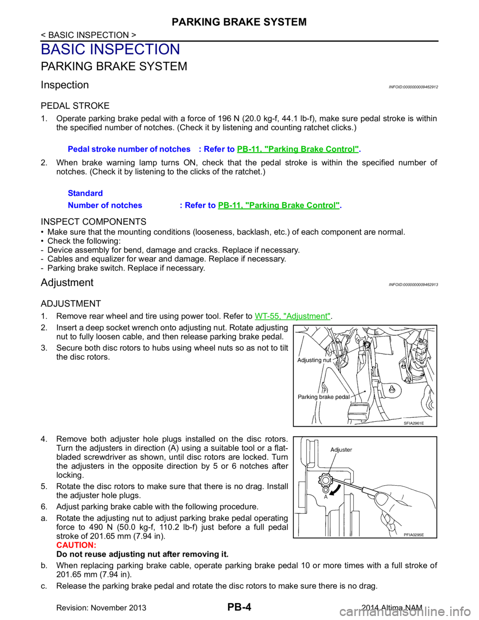
4. Remove both adjuster hole plugs installed on the disc rotors. Turn the adjusters in direction (A) using a suitable tool or a flat-
bladed screwdriver as shown, until disc rotors are locked. Turn
the adjusters in the opposite direction by 5 or 6 notches after
locking.
5. Rotate the disc rotors to make sure that there is no drag. Install the adjuster hole plugs.
6. Adjust parking brake cable with the following procedure.
a. Rotate the adjusting nut to adjust parking brake pedal operating force to 490 N (50.0 kg-f, 110.2 lb-f) just before a full pedal
stroke of 201.65 mm (7.94 in).
CAUTION:
Do not reuse adjusting nut after removing it.
b. When replacing parking brake cable, operate parking brake pedal 10 or more times with a full stroke of 201.65 mm (7.94 in).
c. Release the parking brake pedal and rotate the disc rotors to make sure there is no drag. Pedal stroke number of notches : Refer to
PB-11, "Parking Brake Control"
.
Standard
Number of notches : Refer to PB-11, "Parking Brake Control"
.
SFIA2961E
PFIA0295E
Revision: November 20132014 Altima NAM
Page 3347 of 4801

PARKING BRAKE SHOEPB-9
< REMOVAL AND INSTALLATION >
C
D E
G H
I
J
K L
M A
B
PB
N
O P
PARKING BRAKE SHOE
Exploded ViewINFOID:0000000009462918
Removal and InstallationINFOID:0000000009462919
WARNING:
• Clean brakes with a vacuum dust co llector to minimize the hazard of air borne particles or other
materials.
• Clean dust on disc brake rotor and back plate usin g a vacuum dust collector. Do not blow with com-
pressed air.
CAUTION:
Put matching marks on both disc brake rotor and wheel hub when removing disc rotor.
REMOVAL
1. Remove rear wheel and tire using power tool. Refer to WT-55, "Adjustment".
2. Remove rear brake caliper and disc brake rotor. Refer to BR-40, "BRAKE CALIPER ASSEMBLY :
Removal and Installation".
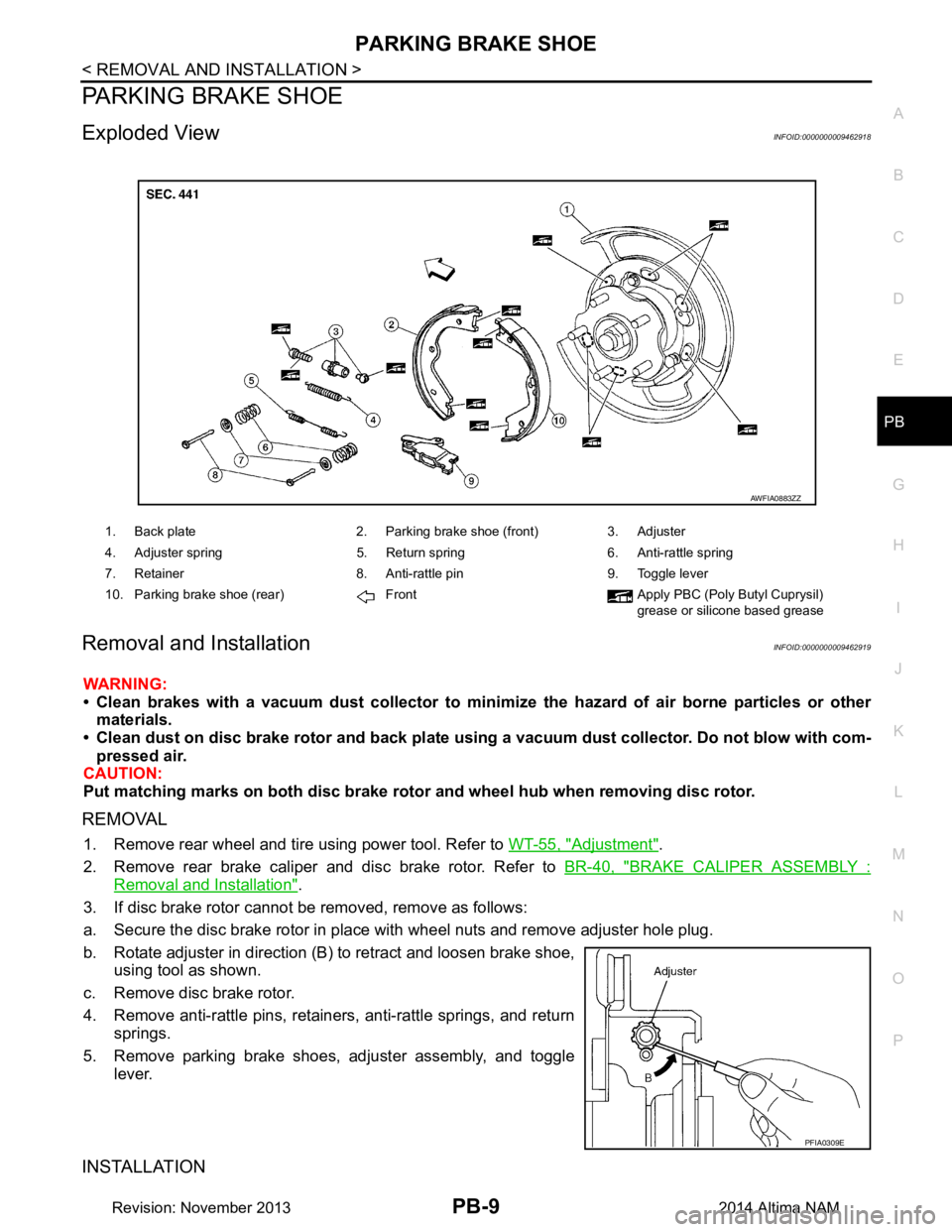
3. If disc brake rotor cannot be removed, remove as follows:
a. Secure the disc brake rotor in place with wheel nuts and remove adjuster hole plug.
b. Rotate adjuster in direction (B) to retract and loosen brake shoe, using tool as shown.
c. Remove disc brake rotor.
4. Remove anti-rattle pins, retainers, anti-rattle springs, and return springs.
5. Remove parking brake shoes, adjuster assembly, and toggle lever.
INSTALLATION
1. Back plate 2. Parking brake shoe (front) 3. Adjuster
4. Adjuster spring 5. Return spring 6. Anti-rattle spring
7. Retainer 8. Anti-rattle pin 9. Toggle lever
10. Parking brake shoe (rear) Front Apply PBC (Poly Butyl Cuprysil) grease or silicone based grease
AWFIA0883ZZ
PFIA0309E
Revision: November 20132014 Altima NAM
Page 3349 of 4801

SERVICE DATA AND SPECIFICATIONS (SDS)PB-11
< SERVICE DATA AND SPECIFICATIONS (SDS)
C
D E
G H
I
J
K L
M A
B
PB
N
O P
SERVICE DATA AND SPECIFICATIONS (SDS)
SERVICE DATA AND SPECIFICATIONS (SDS)
Parking Drum BrakeINFOID:0000000009462920
Unit: mm (in)
Parking Brake ControlINFOID:0000000009462921
Brake lining Standard thickness (new) 3.2 (0.126)
Wear limit thickness 1.5 (0.059)
Drum (in disc) Standard inner diameter (new) 172 (6.77)
Wear limit of inner diameter 173 (6.81)
Control type Foot pedal
Number of notches [under force of 196 N (20.0 kg-f, 44.1 lb-f)] 6 - 7
Number of notches when parking brake warning lamp turns on 1
Revision: November 20132014 Altima NAM
Page 3352 of 4801
![NISSAN TEANA 2014 Service Manual
PCS
PRECAUTIONSPCS-3
< PRECAUTION > [IPDM E/R]
C
D E
F
G H
I
J
K L
B
A
O P
N
PRECAUTION
PRECAUTIONS
Precaution for Supplemental
Restraint System (SRS) "AIR BAG" and "SEAT BELT
PRE-TENSIONER"
INFO NISSAN TEANA 2014 Service Manual
PCS
PRECAUTIONSPCS-3
< PRECAUTION > [IPDM E/R]
C
D E
F
G H
I
J
K L
B
A
O P
N
PRECAUTION
PRECAUTIONS
Precaution for Supplemental
Restraint System (SRS) "AIR BAG" and "SEAT BELT
PRE-TENSIONER"
INFO](/manual-img/5/57390/w960_57390-3351.png)
PCS
PRECAUTIONSPCS-3
< PRECAUTION > [IPDM E/R]
C
D E
F
G H
I
J
K L
B
A
O P
N
PRECAUTION
PRECAUTIONS
Precaution for Supplemental
Restraint System (SRS) "AIR BAG" and "SEAT BELT
PRE-TENSIONER"
INFOID:0000000009951596
The Supplemental Restraint System such as “A IR BAG” and “SEAT BELT PRE-TENSIONER”, used along
with a front seat belt, helps to reduce the risk or severi ty of injury to the driver and front passenger for certain
types of collision. Information necessary to service t he system safely is included in the SR and SB section of
this Service Manual.
WARNING:
• To avoid rendering the SRS inoper ative, which could increase the risk of personal injury or death in
the event of a collision which would result in air bag inflation, all maintenance must be performed by
an authorized NISSAN/INFINITI dealer.
• Improper maintenance, including in correct removal and installation of the SRS, can lead to personal
injury caused by unintentional act ivation of the system. For removal of Spiral Cable and Air Bag
Module, see the SR section.
• Do not use electrical test equipm ent on any circuit related to the SRS unless instructed to in this
Service Manual. SRS wiring harnesses can be identi fied by yellow and/or orange harnesses or har-
ness connectors.
PRECAUTIONS WHEN USING POWER TOOLS (AIR OR ELECTRIC) AND HAMMERS
WARNING:
• When working near the Airbag Diagnosis Sensor Un it or other Airbag System sensors with the Igni-
tion ON or engine running, DO NOT use air or el ectric power tools or strike near the sensor(s) with a
hammer. Heavy vibration could activate the sensor( s) and deploy the air bag(s), possibly causing
serious injury.
• When using air or electric power tools or hammers , always switch the Ignition OFF, disconnect the
battery and wait at least three mi nutes before performing any service.
Precaution for Procedure without Cowl Top CoverINFOID:0000000009461595
When performing the procedure after removing cowl top cover, cover
the lower end of windshield with urethane, etc.
PIIB3706J
Revision: November 20132014 Altima NAMRevision: November 20132014 Altima NAM
Page 3359 of 4801
![NISSAN TEANA 2014 Service Manual
PCS-10
< SYSTEM DESCRIPTION >[IPDM E/R]
DIAGNOSIS SYSTEM (IPDM E/R)
APPLICATION ITEM
CONSULT performs the following functions
via CAN communication with IPDM E/R.
ECU IDENTIFICATION
The IPDM E/R par NISSAN TEANA 2014 Service Manual
PCS-10
< SYSTEM DESCRIPTION >[IPDM E/R]
DIAGNOSIS SYSTEM (IPDM E/R)
APPLICATION ITEM
CONSULT performs the following functions
via CAN communication with IPDM E/R.
ECU IDENTIFICATION
The IPDM E/R par](/manual-img/5/57390/w960_57390-3358.png)
PCS-10
< SYSTEM DESCRIPTION >[IPDM E/R]
DIAGNOSIS SYSTEM (IPDM E/R)
APPLICATION ITEM
CONSULT performs the following functions
via CAN communication with IPDM E/R.
ECU IDENTIFICATION
The IPDM E/R part number is displayed.
SELF DIAGNOSTIC RESULT
Refer to PCS-20, "DTC Index".
DATA MONITOR
Direct Diagnostic Mode Description
Ecu Identification The IPDM E/R part number is displayed.
Self Diagnostic Result The IPDM E/R self diagnostic results are displayed.
Data Monitor The IPDM E/R input/output data is displayed in real time.
Active Test The IPDM E/R activates outputs to test components.
CAN Diag Support Mntr The result of transmit/receive diagnosis of CAN communication is displayed.
Monitor Item [Unit] Main
Signals Description
MOTOR FAN REQ [%] ×Indicates cooling fan speed signal received from ECM on CAN communication
line
AC COMP REQ [On/Off] ×Indicates A/C compressor request signal received from ECM on CAN commu-
nication line
TAIL&CLR REQ [On/Off] ×Indicates position light request signal received from BCM on CAN communica-
tion line
HL LO REQ [On/Off] ×Indicates low beam request signal received from BCM on CAN communication
line
HL HI REQ [On/Off] ×Indicates high beam request signal received from BCM on CAN communication
line
FR FOG REQ [On/Off] ×Indicates front fog light request signal received from BCM on CAN communica-
tion line
FR WIP REQ [Stop/1LOW/Low/Hi] ×Indicates front wiper request signal received from BCM on CAN communication
line
WIP AUTO STOP [STOP P/ACT P] ×Indicates condition of front wiper auto stop signal
WIP PROT [Off/BLOCK] ×Indicates condition of front wiper fail-safe operation
IGN RLY1 -REQ [On/Off] Indicates ignition switch ON signal received from BCM on CAN communication
line
IGN RLY [On/Off] ×Indicates condition of ignition relay
PUSH SW [On/Off] Indicates condition of push-button ignition switch
INTER/NP SW [On/Off] Indicates condition of CVT shift position
ST RLY CONT [On/Off] Indicates starter relay status signal received from BCM on CAN communication
line
IHBT RLY -REQ [On/Off] Indicates starter control relay signal received from BCM on CAN communication
line
ST/INHI RLY [Off/ ST /INHI] Indicates condition of starter relay and starter control relay
DETENT SW [On/Off] Indicates condition of CVT shift selector (park position switch)
DTRL REQ [Off] Indicates daytime light request signal received from BCM on CAN communica-
tion line
HOOD SW [On/Off] Indicates condition of hood switch
THFT HRN REQ [On/Off] Indicates theft warning horn request signal received from BCM on CAN commu-
nication line
Revision: November 20132014 Altima NAMRevision: November 20132014 Altima NAM