2014 NISSAN TEANA wheel alignment
[x] Cancel search: wheel alignmentPage 3723 of 4801
RSU-6
< PERIODIC MAINTENANCE >
REAR SUSPENSION ASSEMBLY
• Check the wheelarch height in the unladen condition. Refer to RSU-17, "Wheelarch Height (Unladen*1)".
GENERAL INFORMATION AND RECOMMENDATIONS
1. A Four-Wheel Thrust Alignment should be performed.
• This type of alignment is recommended for any NISSAN vehicle.
• The four-wheel “thrust” process helps ensure that the vehicle is properly aligned and the steering wheel
is centered.
• The alignment machine itself should be ca pable of accepting any NISSAN vehicle.
• The alignment machine should be checked to ensure that it is level.
2. Make sure the alignment machine is properly calibrated. • Your alignment machine should be regularly calibrated in order to give correct information.
• Check with the manufacturer of your specific al ignment machine for their recommended Service/Cali-
bration Schedule.
THE ALIGNMENT PROCESS
IMPORTANT: Use only the alignment specifications listed in this Service Manual. Refer to RSU-17,
"Wheelarch Height (Unladen*1)".
1. When displaying the alignment settings, many alignm ent machines use “indicators”: (Green/red, plus or
minus, Go/No Go). Do NOT use these indicators.
• The alignment specifications programmed into your alignment machine that operate these indicators
may not be correct.
• This may result in an ERROR.
2. Most camera-type alignment machines are equipped with both "Rolling Compensation" method and optional "Jacking Compensation" method to "com pensate" the alignment targets or head units.
"Rolling Compensation" is the preferred method.
• If using the "Rolling Compensation" method, after installing the alignment targets or head units, push or pull on the rear wheel to move the vehicle. Do not push or pull the vehicle body.
• If using the "Jacking Compensation" method, after in stalling the alignment targets or head units, raise
the vehicle and rotate the wheels 1/2 turn both ways.
NOTE:
Do not use the "Rolling Compensation" method if you are using sensor-type alignment equipment.
• Follow all instructions for the alignment machine you are using for more information.
CAMBER and TOE
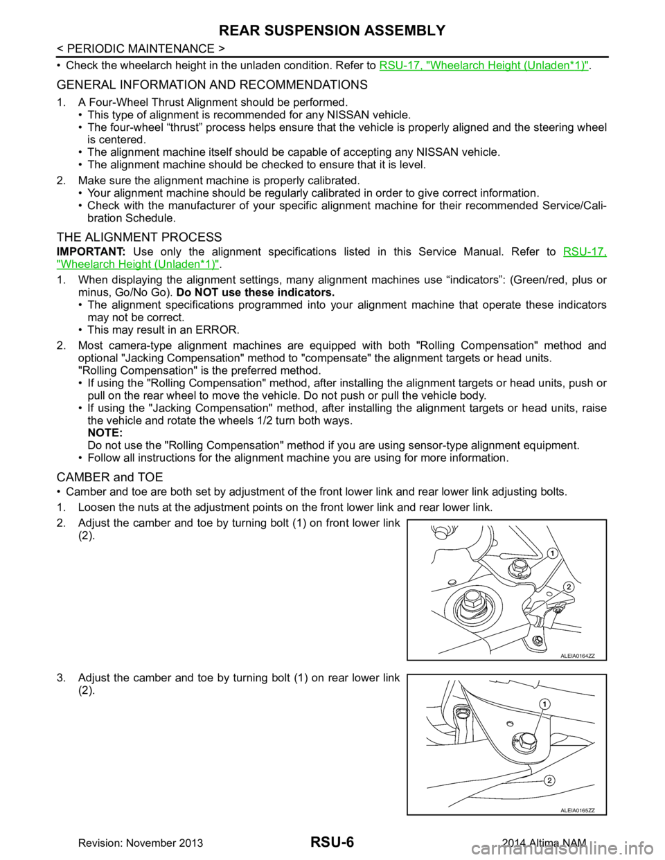
• Camber and toe are both set by adjustment of the fr ont lower link and rear lower link adjusting bolts.
1. Loosen the nuts at the adjustment points on the front lower link and rear lower link.
2. Adjust the camber and toe by turning bolt (1) on front lower link (2).
3. Adjust the camber and toe by turning bolt (1) on rear lower link (2).
ALEIA0164ZZ
ALEIA0165ZZ
Revision: November 20132014 Altima NAM
Page 3724 of 4801
REAR SUSPENSION ASSEMBLYRSU-7
< PERIODIC MAINTENANCE >
C
D
F
G H
I
J
K L
M A
B
RSU
N
O P
NOTE:
• Camber changes about 0 ° 5’ (0.08 °) with each graduation of the adjusting bolt.
• Turn the adjusting bolts in the same direction to calibrate camber.
• Toe changes about 1.5 mm (0.059 in) [one side] with each graduation of the adjusting bolt.
• Turn the adjusting bolts in the opposite direction to calibrate toe.
4. Tighten the adjusting bolt nuts to the specified torque. Camber : Refer to
RSU-17, "Wheel Alignment (Unlad-
en*)".
Total toe-in : Refer to RSU-17, "Wheel Alignment (Unlad-
en*)".
Adjusting bolt nuts : Refer to RSU-8, "Exploded View"
.
Revision: November 20132014 Altima NAM
Page 3728 of 4801
REAR SUSPENSION ASSEMBLYRSU-11
< UNIT REMOVAL AND INSTALLATION >
C
D
F
G H
I
J
K L
M A
B
RSU
N
O P
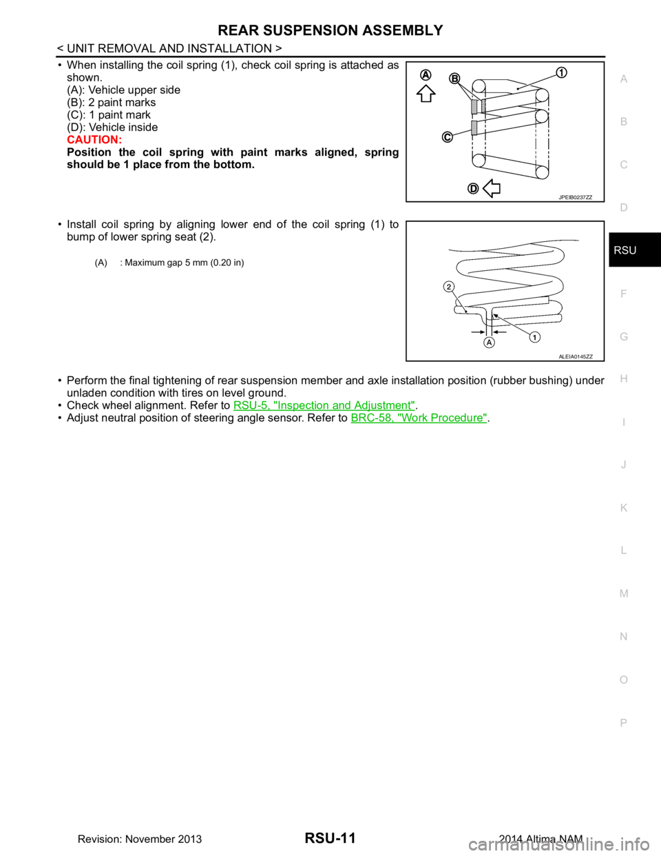
• When installing the coil spring (1), check coil spring is attached as shown.
(A): Vehicle upper side
(B): 2 paint marks
(C): 1 paint mark
(D): Vehicle inside
CAUTION:
Position the coil spring with paint marks aligned, spring
should be 1 place from the bottom.
• Install coil spring by aligning lower end of the coil spring (1) to bump of lower spring seat (2).
• Perform the final tightening of rear suspension me mber and axle installation position (rubber bushing) under
unladen condition with tires on level ground.
• Check wheel alignment. Refer to RSU-5, "Inspection and Adjustment"
.
• Adjust neutral position of steering angle sensor. Refer to BRC-58, "Work Procedure"
.
JPEIB0237ZZ
(A) : Maximum gap 5 mm (0.20 in)
ALEIA0145ZZ
Revision: November 20132014 Altima NAM
Page 3733 of 4801
RSU-16
< REMOVAL AND INSTALLATION >
SUSPENSION ARM
SUSPENSION ARM
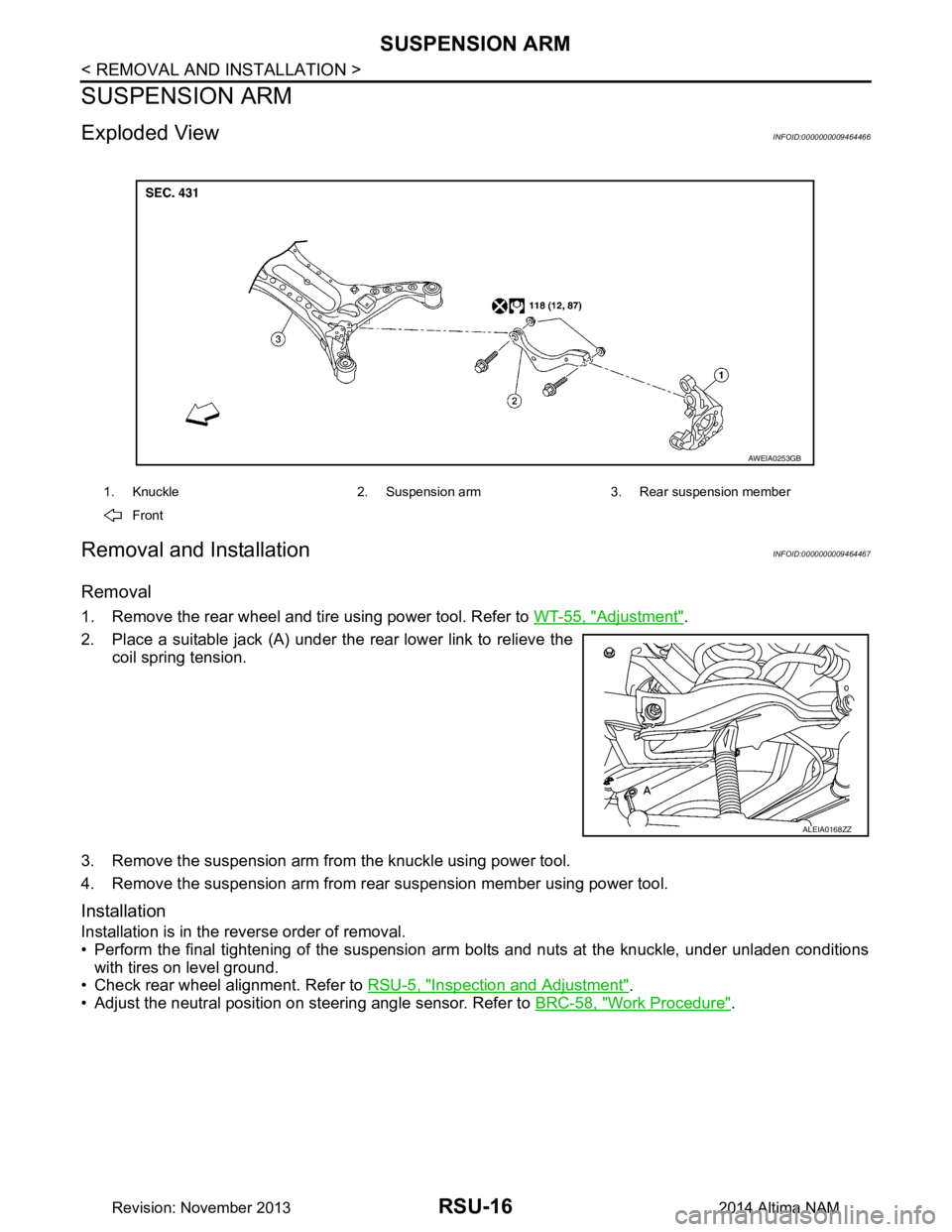
Exploded ViewINFOID:0000000009464466
Removal and InstallationINFOID:0000000009464467
Removal
1. Remove the rear wheel and tire using power tool. Refer to WT-55, "Adjustment".
2. Place a suitable jack (A) under the rear lower link to relieve the coil spring tension.
3. Remove the suspension arm from the knuckle using power tool.
4. Remove the suspension arm from rear suspension member using power tool.
Installation
Installation is in the reverse order of removal.
• Perform the final tightening of the suspension arm bolts and nuts at the knuckle, under unladen conditions
with tires on level ground.
• Check rear wheel alignment. Refer to RSU-5, "Inspection and Adjustment"
.
• Adjust the neutral position on steering angle sensor. Refer to BRC-58, "Work Procedure"
.
1. Knuckle 2. Suspension arm 3. Rear suspension member
Front
AWEIA0253GB
ALEIA0168ZZ
Revision: November 20132014 Altima NAM
Page 3734 of 4801
SERVICE DATA AND SPECIFICATIONS (SDS)RSU-17
< SERVICE DATA AND SPECIFICATIONS (SDS)
C
D
F
G H
I
J
K L
M A
B
RSU
N
O P
SERVICE DATA AND SPECIFICATIONS (SDS)
SERVICE DATA AND SPECIFICATIONS (SDS)
General Specification (Rear)INFOID:0000000009464468
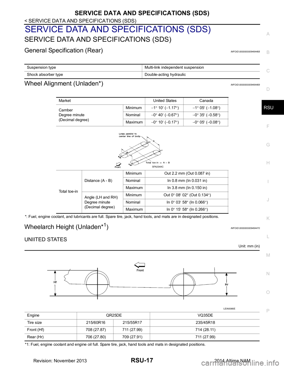
Wheel Alignment (Unladen*)INFOID:0000000009464469
*: Fuel, engine coolant, and lubricants are full. Spare tire, jack, hand tools, and mats are in designated positions.
Wheelarch Height (Unladen*1)INFOID:0000000009464470
UNIITED STATES
Unit: mm (in)
*1: Fuel, engine coolant and engine oil full. Spare tire, jack, hand tools and mats in designated positions. Suspension type Multi-link independent suspension
Shock absorber type Double-acting hydraulic
Market United States Canada
Camber
Degree minute
(Decimal degree) Minimum
−1° 10 ′ ( −1.17 °) −1 ° 05 ′ ( −1.08 °)
Nominal −0° 40 ′ ( −0.67 °) −0 ° 35 ′ ( −0.58 °)
Maximum −0° 10 ′ ( −0.17 °) −0 ° 05 ′ ( −0.08 °)
Total toe-in Distance (A - B)
Minimum Out 2.2 mm (Out 0.087 in)
Nominal In 0.8 mm (In 0.031 in)
Maximum In 3.8 mm (In 0.150 in)
Angle (LH and RH)
Degree minute
(Decimal degree) Minimum Out 0
° 08 ′ 02 ″ (Out 0.134 °)
Nominal In 0 ° 03 ′ 58 ″ (In 0.066 °)
Maximum In 0 ° 15 ′ 58 ″ (In 0.266 °)
SFA234AC
Engine QR25DE VQ35DE
Tire size 215/60R16 215/55R17 235/45R18
Front (Hf) 708 (27.87) 711 (27.99) 714 (28.11)
Rear (Hr) 706 (27.80) 709 (27.91) 711 (27.99)
LEIA0085E
Revision: November 20132014 Altima NAM
Page 3967 of 4801
COLLISION DIAGNOSISSR-5
< BASIC INSPECTION >
C
D E
F
G
I
J
K L
M A
B
SR
N
O P
BASIC INSPECTION
COLLISION DIAGNOSIS
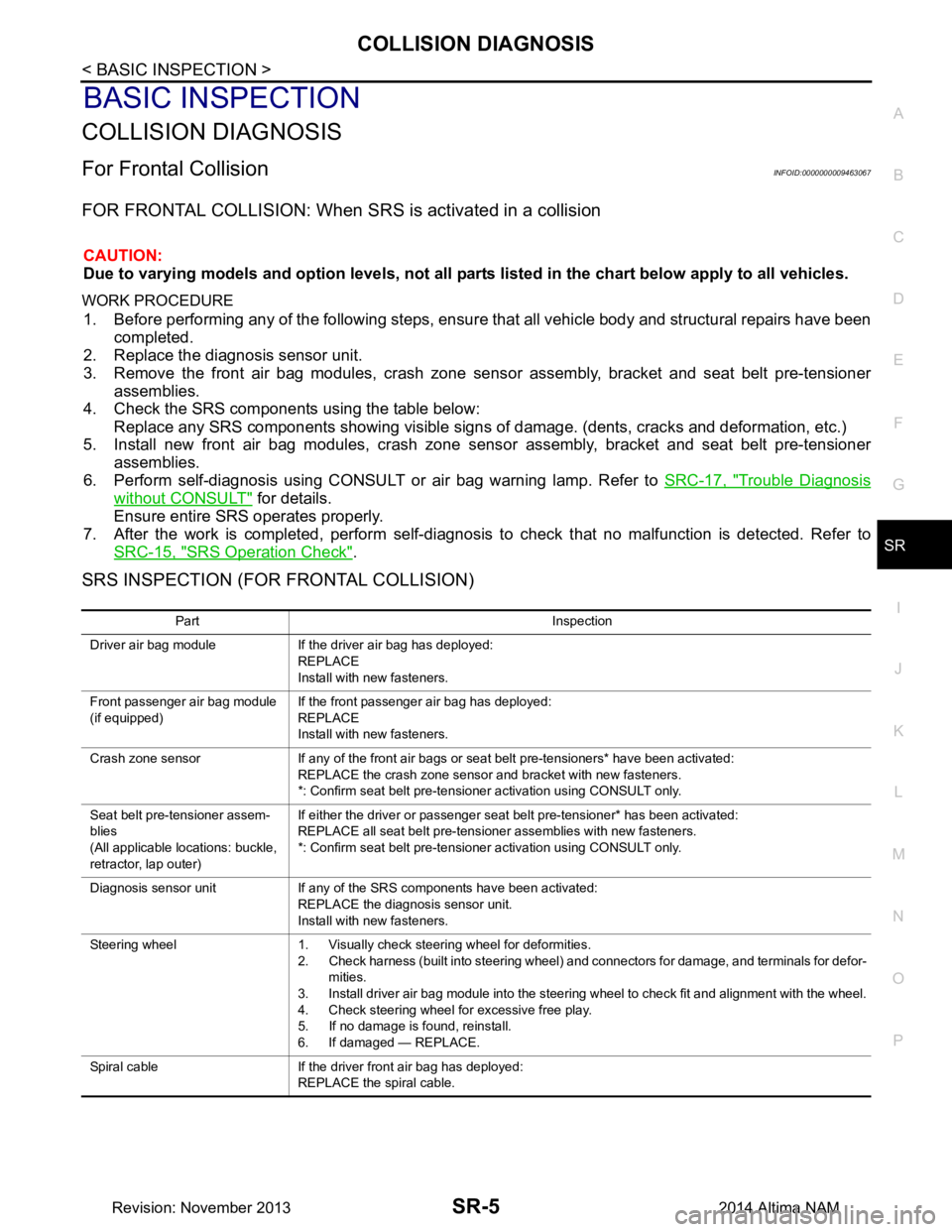
For Frontal CollisionINFOID:0000000009463067
FOR FRONTAL COLLISION: When SRS is activated in a collision
CAUTION:
Due to varying models and option levels, not all parts listed in the chart below apply to all vehicles.
WORK PROCEDURE
1. Before performing any of the following steps, ensur e that all vehicle body and structural repairs have been
completed.
2. Replace the diagnosis sensor unit.
3. Remove the front air bag modules, crash zone sens or assembly, bracket and seat belt pre-tensioner
assemblies.
4. Check the SRS components using the table below:
Replace any SRS components showing visible signs of damage. (dents, cracks and deformation, etc.)
5. Install new front air bag modules, crash zone sens or assembly, bracket and seat belt pre-tensioner
assemblies.
6. Perform self-diagnosis using CONSULT or air bag warning lamp. Refer to SRC-17, "Trouble Diagnosis
without CONSULT" for details.
Ensure entire SRS operates properly.
7. After the work is completed, perform self-diagnosis to check that no malfunction is detected. Refer to
SRC-15, "SRS Operation Check"
.
SRS INSPECTION (FOR FRONTAL COLLISION)
Part Inspection
Driver air bag module If the driver air bag has deployed: REPLACE
Install with new fasteners.
Front passenger air bag module
(if equipped) If the front passenger air bag has deployed:
REPLACE
Install with new fasteners.
Crash zone sensor If any of the front air bags or seat belt pre-tensioners* have been activated: REPLACE the crash zone sensor and bracket with new fasteners.
*: Confirm seat belt pre-tensioner activation using CONSULT only.
Seat belt pre-tensioner assem-
blies
(All applicable locations: buckle,
retractor, lap outer) If either the driver or passenger seat belt pre-tensioner* has been activated:
REPLACE all seat belt pre-tensioner assemblies with new fasteners.
*: Confirm seat belt pre-tensioner activation using CONSULT only.
Diagnosis sensor unit If any of the SRS components have been activated: REPLACE the diagnosis sensor unit.
Install with new fasteners.
Steering wheel 1. Visually check steering wheel for deformities. 2. Check harness (built into steering wheel) and connectors for damage, and terminals for defor-
mities.
3. Install driver air bag module into the steering wheel to check fit and alignment with the wheel.
4. Check steering wheel for excessive free play.
5. If no damage is found, reinstall.
6. If damaged — REPLACE.
Spiral cable If the driver front air bag has deployed: REPLACE the spiral cable.
Revision: November 20132014 Altima NAM
Page 3968 of 4801
SR-6
< BASIC INSPECTION >
COLLISION DIAGNOSIS
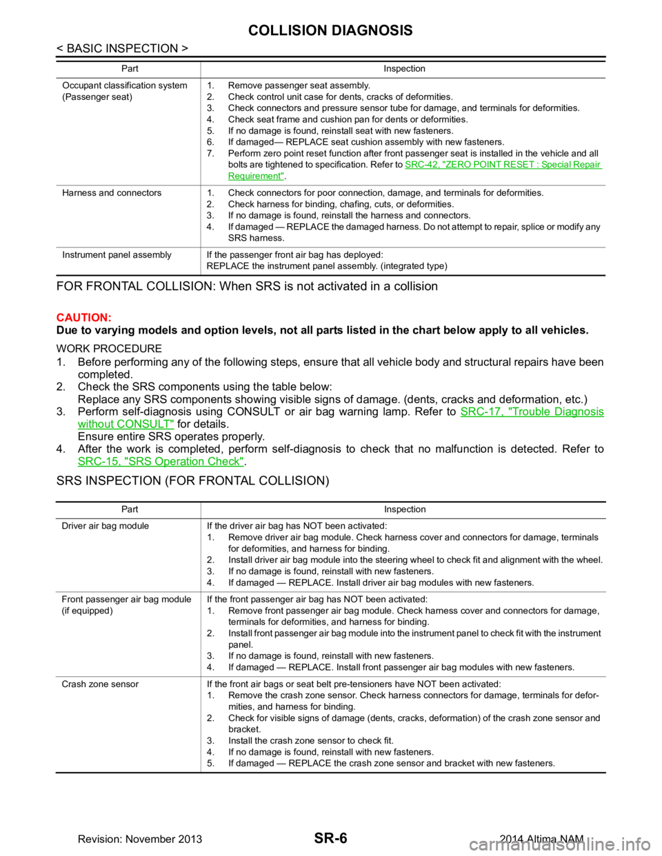
FOR FRONTAL COLLISION: When SRS is not activated in a collision
CAUTION:
Due to varying models and option levels, not all part s listed in the chart below apply to all vehicles.
WORK PROCEDURE
1. Before performing any of the following steps, ensur e that all vehicle body and structural repairs have been
completed.
2. Check the SRS components using the table below:
Replace any SRS components showing visible signs of damage. (dents, cracks and deformation, etc.)
3. Perform self-diagnosis using CONSULT or air bag warning lamp. Refer to SRC-17, "Trouble Diagnosis
without CONSULT" for details.
Ensure entire SRS operates properly.
4. After the work is completed, perform self-diagnosis to check that no malfunction is detected. Refer to
SRC-15, "SRS Operation Check"
.
SRS INSPECTION (FOR FRONTAL COLLISION)
Occupant classification system
(Passenger seat) 1. Remove passenger seat assembly.
2. Check control unit case for dents, cracks of deformities.
3. Check connectors and pressure sensor tube for damage, and terminals for deformities.
4. Check seat frame and cushion pan for dents or deformities.
5. If no damage is found, reinstall seat with new fasteners.
6. If damaged— REPLACE seat cushion assembly with new fasteners.
7. Perform zero point reset function after front passenger seat is installed in the vehicle and all bolts are tightened to specification. Refer to SRC-42, "ZERO POINT RESET : Special Repair
Requirement".
Harness and connectors 1. Check connectors for poor connection, damage, and terminals for deformities. 2. Check harness for binding, chafing, cuts, or deformities.
3. If no damage is found, reinstall the harness and connectors.
4. If damaged — REPLACE the damaged harness. Do not attempt to repair, splice or modify any SRS harness.
Instrument panel assembly If the passenger front air bag has deployed: REPLACE the instrument panel assembly. (integrated type)
Part Inspection
Part Inspection
Driver air bag module If the driver air bag has NOT been activated: 1. Remove driver air bag module. Check harness cover and connectors for damage, terminals for deformities, and harness for binding.
2. Install driver air bag module into the steering wheel to check fit and alignment with the wheel.
3. If no damage is found, reinstall with new fasteners.
4. If damaged — REPLACE. Install driver air bag modules with new fasteners.
Front passenger air bag module
(if equipped) If the front passenger air bag has NOT been activated:
1. Remove front passenger air bag module. Check harness cover and connectors for damage, terminals for deformities, and harness for binding.
2. Install front passenger air bag module into the instrument panel to check fit with the instrument panel.
3. If no damage is found, reinstall with new fasteners.
4. If damaged — REPLACE. Install front passenger air bag modules with new fasteners.
Crash zone sensor If the front air bags or seat belt pre-tensioners have NOT been activated: 1. Remove the crash zone sensor. Check harness connectors for damage, terminals for defor-mities, and harness for binding.
2. Check for visible signs of damage (dents, cracks, deformation) of the crash zone sensor and bracket.
3. Install the crash zone sensor to check fit.
4. If no damage is found, reinstall with new fasteners.
5. If damaged — REPLACE the crash zone sensor and bracket with new fasteners.
Revision: November 20132014 Altima NAM
Page 3969 of 4801
COLLISION DIAGNOSISSR-7
< BASIC INSPECTION >
C
D E
F
G
I
J
K L
M A
B
SR
N
O P
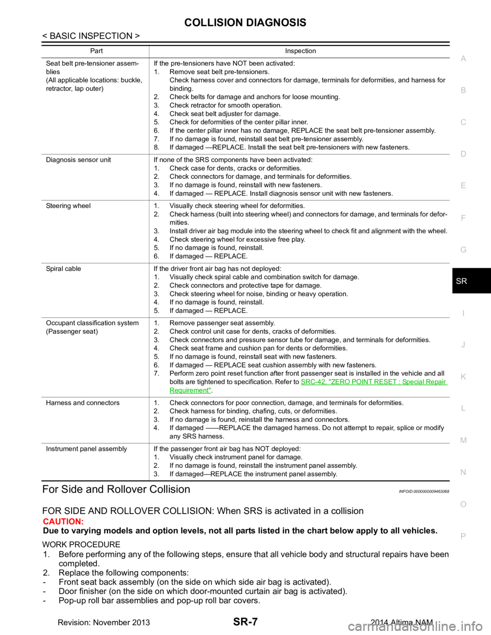
For Side and Rollover CollisionINFOID:0000000009463068
FOR SIDE AND ROLLOVER COLLISION: When SRS is activated in a collision
CAUTION:
Due to varying models and option levels, not all parts listed in the chart below apply to all vehicles.
WORK PROCEDURE
1. Before performing any of the following steps, ensur e that all vehicle body and structural repairs have been
completed.
2. Replace the following components:
- Front seat back assembly (on the side on which side air bag is activated).
- Door finisher (on the side on which door-mounted curtain air bag is activated).
- Pop-up roll bar assemblies and pop-up roll bar covers.
Seat belt pre-tensioner assem-
blies
(All applicable locations: buckle,
retractor, lap outer) If the pre-tensioners have NOT been activated:
1. Remove seat belt pre-tensioners.
Check harness cover and connectors for damage, terminals for deformities, and harness for
binding.
2. Check belts for damage and anchors for loose mounting.
3. Check retractor for smooth operation.
4. Check seat belt adjuster for damage.
5. Check for deformities of the center pillar inner.
6. If the center pillar inner has no damage, REPLACE the seat belt pre-tensioner assembly.
7. If no damage is found, reinstall seat belt pre-tensioner assembly.
8. If damaged —REPLACE. Install the seat belt pre-tensioners with new fasteners.
Diagnosis sensor unit If none of the SRS components have been activated: 1. Check case for dents, cracks or deformities.
2. Check connectors for damage, and terminals for deformities.
3. If no damage is found, reinstall with new fasteners.
4. If damaged — REPLACE. Install diagnosis sensor unit with new fasteners.
Steering wheel 1. Visually check steering wheel for deformities. 2. Check harness (built into steering wheel) and connectors for damage, and terminals for defor-mities.
3. Install driver air bag module into the steering wheel to check fit and alignment with the wheel.
4. Check steering wheel for excessive free play.
5. If no damage is found, reinstall.
6. If damaged — REPLACE.
Spiral cable If the driver front air bag has not deployed: 1. Visually check spiral cable and combination switch for damage.
2. Check connectors and protective tape for damage.
3. Check steering wheel for noise, binding or heavy operation.
4. If no damage is found, reinstall.
5. If damaged — REPLACE.
Occupant classification system
(Passenger seat) 1. Remove passenger seat assembly.
2. Check control unit case for dents, cracks of deformities.
3. Check connectors and pressure sensor tube for damage, and terminals for deformities.
4. Check seat frame and cushion pan for dents or deformities.
5. If no damage is found, reinstall seat with new fasteners.
6. If damaged — REPLACE seat cushion assembly with new fasteners.
7. Perform zero point reset function after front passenger seat is installed in the vehicle and all
bolts are tightened to specification. Refer to SRC-42, "ZERO POINT RESET : Special Repair
Requirement".
Harness and connectors 1. Check connectors for poor connection, damage, and terminals for deformities. 2. Check harness for binding, chafing, cuts, or deformities.
3. If no damage is found, reinstall the harness and connectors.
4. If damaged ——REPLACE the damaged harness. Do not attempt to repair, splice or modify any SRS harness.
Instrument panel assembly If the passenger front air bag has NOT deployed: 1. Visually check instrument panel for damage.
2. If no damage is found, reinstall the instrument panel assembly.
3. If damaged—REPLACE the instrument panel assembly.
Part Inspection
Revision: November 20132014 Altima NAM