2014 NISSAN TEANA wheel alignment
[x] Cancel search: wheel alignmentPage 5 of 4801

QUICK REFERENCE CHART: ALTIMA
2014
Drive BeltINFOID:0000000010112420
DRIVE BELT
Spark PlugINFOID:0000000010112421
SPARK PLUG
Unit: mm (in)
*: Always check with the Parts Department for the latest parts information.
Front Wheel Alignment (Unladen*1)INFOID:0000000010112418
UNITED STATES
Cylinder number
Valve timing
(Valve timing control - “OFF”)Unit: degree
abcde f
240 240−
10 (-35)
AT D C 70(25)
ABDC 10
50
SEM713A
PBIC0187E
Tension of drive belt Belt tension is not necessary, as it is automatically adjusted by drive belt auto-tensioner.
Make DENSO
Standard type* FXE22HR11
Gap Standard 1.1 (0.043)
Engine type QR25DEVQ35DE
Tire size 215/60R16 215/55R17235/45R18
Page 7 of 4801

QUICK REFERENCE CHART: ALTIMA
2014
*1: Fuel, engine coolant, and lubricants are full. Spare tire, jack, hand tools, and mats are in designated positions.
*2: The RH camber angle shall be -0° 15 ′± 0 ° 33′ (-0.25 °± 0.55 °) with respect to the LH camber angle.
*3: For the caster angle, the difference between right and left against the ground surface shall be ± 0 ° 30 ′ ( ± 0.50 °) maximum.
Rear Wheel Alignment (Unladen*)INFOID:0000000010112416
*: Fuel, engine coolant, and lubricants are full. Spare tire, jack, hand tools, and mats are in designated positions.
Wheelarch Height (Unladen*1)INFOID:0000000010112417
UNITED STATES
Kingpin inclination
Degree minute
(Decimal degree) (LH)
Minimum
13° 35 ′ (13.58 °)1 3° 40 ′ (13.67 °)
Nominal 14° 20 ′ (14.33 °)1 4° 25 ′ (14.42 °)
Maximum 15° 05 ′ (15.08 °)1 5° 10 ′ (15.17 °)
(RH) Minimum
13° 50 ′ (13.83 °)1 3° 55 ′ (13.92 °)
Nominal 14° 35 ′ (14.58 °)1 4° 40 ′ (14.67 °)
Maximum 15° 20 ′ (15.33 °)1 5° 25 ′ (15.42 °)
To t a l t o e - i n Distance (A - B)
Minimum
Out 1.7 mm (Out 0.07 in)
Nominal In 0.3 mm (In 0.01 in)
Maximum In 2.3 mm (In 0.09 in)
Angle (LH and RH)
Degree minute
(Decimal degree) Minimum
Out 0° 05 ′ 38 ″ (Out 0.094 °)
Nominal In 0° 03 ′ 57 ″ (I
n 0.066 °)
Maximum In 0° 13 ′ 33 ″ (In 0.226 °)
SFA234AC
Market United StatesCanada
Camber
Degree minute
(Decimal degree) Minimum
−1° 10 ′ ( −1.17 °) −1 ° 05 ′ ( −1.08° )
Nominal −0° 40 ′ ( −0.67 °) −0 ° 35 ′ ( −0.58° )
Maximum −0° 10 ′ ( −0.17 °) −0 ° 05 ′ ( −0.08° )
Total toe-in Distance (A - B)
Minimum
Out 2.2 mm (Out 0.087 in)
Nominal In 0.8 mm (In 0.031 in)
Maximum In 3.8 mm (In 0.150 in)
Angle (LH and RH)
Degree minute
(Decimal degree) Minimum
Out 0° 08′ 02 ″ (Out 0.134° )
Nominal In 0° 03 ′ 58 ″ (In 0.066 °)
Maximum In 0° 15′ 58 ″ (In 0.266 °)
SFA234AC
Page 204 of 4801
![NISSAN TEANA 2014 Service Manual
BRC-58
< BASIC INSPECTION >[VDC/TCS/ABS]
ADJUSTMENT OF STEERING ANGLE
SENSOR NEUTRAL POSITION
ADJUSTMENT OF STEERING ANGLE SENSOR NEUTRAL POSITION
DescriptionINFOID:0000000009463767
Refer to the tab NISSAN TEANA 2014 Service Manual
BRC-58
< BASIC INSPECTION >[VDC/TCS/ABS]
ADJUSTMENT OF STEERING ANGLE
SENSOR NEUTRAL POSITION
ADJUSTMENT OF STEERING ANGLE SENSOR NEUTRAL POSITION
DescriptionINFOID:0000000009463767
Refer to the tab](/manual-img/5/57390/w960_57390-203.png)
BRC-58
< BASIC INSPECTION >[VDC/TCS/ABS]
ADJUSTMENT OF STEERING ANGLE
SENSOR NEUTRAL POSITION
ADJUSTMENT OF STEERING ANGLE SENSOR NEUTRAL POSITION
DescriptionINFOID:0000000009463767
Refer to the table below to determine if adjustment of steering angle sensor neutral position is required.
×: Required –: Not required
Work ProcedureINFOID:0000000009463768
ADJUSTMENT OF STEERING ANGLE SENSOR NEUTRAL POSITION
CAUTION:
To adjust neutral position of steering an gle sensor, make sure to use CONSULT.
(Adjustment cannot be done without CONSULT).
1.ALIGN THE VEHICLE STATUS
Stop vehicle with front wheels in straight-ahead position.
>> GO TO 2.
2.PERFORM THE NEUTRAL POSITION ADJUST MENT FOR THE STEERING ANGLE SENSOR
1. On the CONSULT screen, touch “WORK SUPPO RT” and “ST ANG SEN ADJUSTMENT” in order.
2. Touch “START”.
CAUTION:
Do not touch steering wheel whil e adjusting steering angle sensor.
3. After approximately 10 seconds, touch “END”. NOTE:
After approximately 60 seconds, it ends automatically.
4. Turn ignition switch OFF, then turn it ON again. CAUTION:
Be sure to perform above operation.
>> GO TO 3.
3.CHECK DATA MONITOR
1. Run vehicle with front wheels in straight-ahead position, then stop.
2. Select “DATA MONITOR”. Then make sure “STR ANGLE SIG” is within 0 ±2.5 °.
Is the steering angle within the specified range?
YES >> GO TO 4.
NO >> Perform the neutral position adjustment fo r the steering angle sensor again, GO TO 1
4.ERASE THE SELF-DIAGNOSIS MEMORY
Erase the self-diagnosis memory of the ABS ac tuator and electric unit (control unit) and ECM.
• ABS actuator and electric unit (control unit): Refer to BRC-33, "CONSULT Function (ABS)"
.
Situation Adjustment of steering angle sensor neutral position
Removing/Installing ABS actuator and electric unit (control unit) —
Replacing ABS actuator and electric unit (control unit) ×
Removing/Installing steering angle sensor ×
Replacing steering angle sensor ×
Removing/Installing steering components ×
Replacing steering components ×
Removing/Installing suspension components ×
Replacing suspension components ×
Change tires to new ones —
Tire rotation —
Adjusting wheel alignment ×
Revision: November 20132014 Altima NAMRevision: November 20132014 Altima NAM
Page 208 of 4801
![NISSAN TEANA 2014 Service Manual
BRC-62
< BASIC INSPECTION >[VDC/TCS/ABS]
CALIBRATION OF DECEL G SENSOR
CALIBRATION OF DECEL G SENSOR
DescriptionINFOID:0000000009962236
Refer to the table below to determine if calibration of the dec NISSAN TEANA 2014 Service Manual
BRC-62
< BASIC INSPECTION >[VDC/TCS/ABS]
CALIBRATION OF DECEL G SENSOR
CALIBRATION OF DECEL G SENSOR
DescriptionINFOID:0000000009962236
Refer to the table below to determine if calibration of the dec](/manual-img/5/57390/w960_57390-207.png)
BRC-62
< BASIC INSPECTION >[VDC/TCS/ABS]
CALIBRATION OF DECEL G SENSOR
CALIBRATION OF DECEL G SENSOR
DescriptionINFOID:0000000009962236
Refer to the table below to determine if calibration of the decel G sensor is required.
×
: Required –: Not required
Work ProcedureINFOID:0000000009962237
CALIBRATION OF DECEL G SENSOR
CAUTION:
To calibrate the decel G sensor, make sure to use CONSULT.
(Calibration cannot be done without CONSULT).
1.ALIGN THE VEHICLE STATUS
Stop vehicle with front wheels in straight-ahead position.
>> GO TO 2.
2.PERFORM CALIBRATION OF DECEL G SENSOR
1. On the CONSULT screen, touch “WORK SUPPORT ” and “DECEL G SEN CALIBRATION” in order.
2. Touch “START”.
3. After approximately 10 seconds, touch “END”.
NOTE:
After approximately 60 seconds, it ends automatically.
4. Turn ignition switch OFF, then turn it ON again.
CAUTION:
Be sure to perform above operation.
>> GO TO 3.
3.CHECK DATA MONITOR
1. Run vehicle with front wheels in straight-ahead position, then stop.
2. Select “DATA MONITOR”. Then make sure “DECEL G SEN” is within ± 0.08G.
Is the inspection result normal?
YES >> GO TO 4.
NO >> Perform calibration of decel G sensor again, GO TO 1.
4.ERASE THE SELF-DIAGNOSIS MEMORY
Erase the self-diagnosis memory of the ABS ac tuator and electric unit (control unit) and ECM.
• ABS actuator and electric unit (control unit): Refer to BRC-33, "CONSULT Function (ABS)"
.
• ECM: Refer to EC-77, "CONSULT Function"
(QR25DE) or EC-601, "CONSULT Function" (VQ35DE).
Situation Calibration of decel G sensor
Removing/Installing ABS actuator and electric unit (control unit) —
Replacing ABS actuator and electric unit (control unit) ×
Removing/Installing steering components —
Replacing steering components —
Removing/Installing suspension components —
Replacing suspension components —
Removing/Installing tire —
Replacing tire —
Tire rotation —
Adjusting wheel alignment —
Removing/Installing yaw rate/side/decel G sensor ×
Replacing yaw rate/side/decel G sensor ×
Revision: November 20132014 Altima NAMRevision: November 20132014 Altima NAM
Page 2460 of 4801

FAX-8
< REMOVAL AND INSTALLATION >
FRONT WHEEL HUB
REMOVAL AND INSTALLATION
FRONT WHEEL HUB
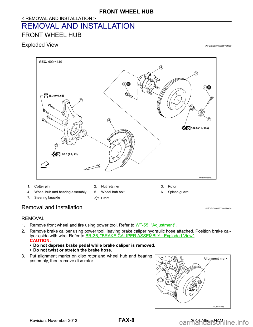
Exploded ViewINFOID:0000000009464438
Removal and InstallationINFOID:0000000009464439
REMOVAL
1. Remove front wheel and tire using power tool. Refer to WT-55, "Adjustment".
2. Remove brake caliper using power tool, leaving brak e caliper hydraulic hose attached. Position brake cal-
iper aside with wire. Refer to BR-36, "BRAKE CALIPER ASSEMBLY : Exploded View"
.
CAUTION:
• Do not depress brake pedal while brake caliper is removed.
• Do not twist or stretch the brake hose.
3. Put alignment marks on disc rotor and wheel hub and bearing assembly, then remove disc rotor.
1. Cotter pin 2. Nut retainer 3. Rotor
4. Wheel hub and bearing assembly 5. Wheel hub bolt 6. Splash guard
7. Steering knuckle Front
AWEIA0264ZZ
SDIA1480E
Revision: November 20132014 Altima NAM
Page 2463 of 4801

FRONT DRIVE SHAFTFAX-11
< REMOVAL AND INSTALLATION >
CEF
G H
I
J
K L
M A
B
FA X
N
O P
9. Put alignment marks on disc rotor and wheel hub and bearing assembly, then remove disc rotor.
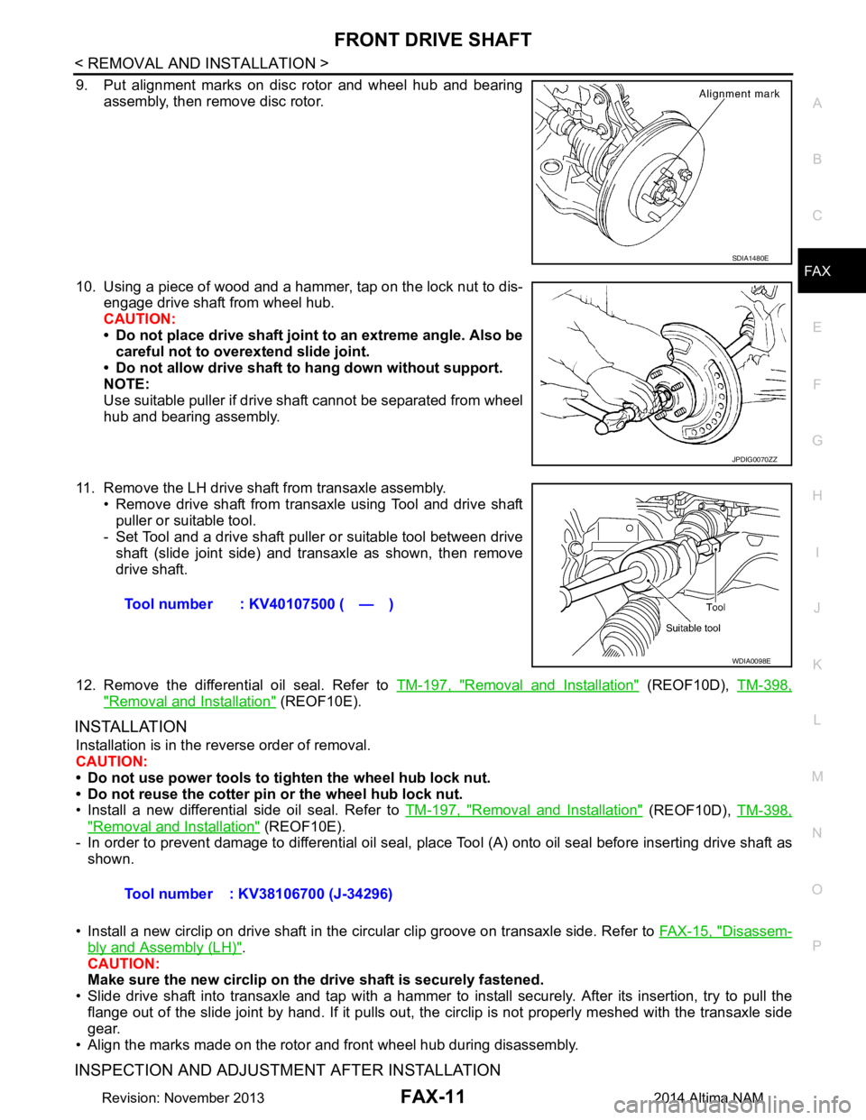
10. Using a piece of wood and a hammer, tap on the lock nut to dis- engage drive shaft from wheel hub.
CAUTION:
• Do not place drive shaft joint to an extreme angle. Also be careful not to over extend slide joint.
• Do not allow drive shaft to hang down without support.
NOTE:
Use suitable puller if drive shaft cannot be separated from wheel
hub and bearing assembly.
11. Remove the LH drive shaf t from transaxle assembly.
• Remove drive shaft from transaxle using Tool and drive shaft puller or suitable tool.
- Set Tool and a drive shaft puller or suitable tool between drive
shaft (slide joint side) and transaxle as shown, then remove
drive shaft.
12. Remove the differential oil seal. Refer to TM-197, "Removal and Installation"
(REOF10D), TM-398,
"Removal and Installation" (REOF10E).
INSTALLATION
Installation is in the reverse order of removal.
CAUTION:
• Do not use power tools to ti ghten the wheel hub lock nut.
• Do not reuse the cotter pin or the wheel hub lock nut.
• Install a new differential side oil seal. Refer to TM-197, "Removal and Installation"
(REOF10D), TM-398,
"Removal and Installation" (REOF10E).
- In order to prevent damage to differential oil seal, plac e Tool (A) onto oil seal before inserting drive shaft as
shown.
• Install a new circlip on drive shaft in the circular clip groove on transaxle side. Refer to FAX-15, "Disassem-
bly and Assembly (LH)".
CAUTION:
Make sure the new circlip on the drive shaft is securely fastened.
• Slide drive shaft into transaxle and tap with a hammer to install securely. After its insertion, try to pull the
flange out of the slide joint by hand. If it pulls out, t he circlip is not properly meshed with the transaxle side
gear.
• Align the marks made on the rotor and front wheel hub during disassembly.
INSPECTION AND ADJUSTMENT AFTER INSTALLATION
SDIA1480E
JPDIG0070ZZ
Tool number : KV40107500 ( — )
WDIA0098E
Tool number : KV38106700 (J-34296)
Revision: November 20132014 Altima NAM
Page 2464 of 4801

FAX-12
< REMOVAL AND INSTALLATION >
FRONT DRIVE SHAFT
1. Check CVT fluid level and leakage. Refer to TM-84, "Adjustment" (REOF10D), TM-286, "Adjustment"
(REOF10E).
2. Check wheel alignment. Refer to FSU-7, "Inspection and Adjustment"
.
3. Adjust the neutral position of the steering angle sensor. Refer to BRC-58, "Work Procedure"
.
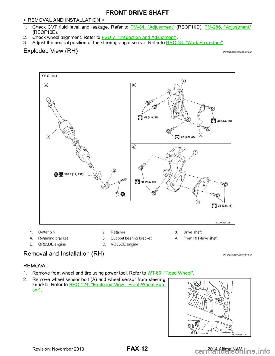
Exploded View (RH)INFOID:0000000009464442
Removal and Installation (RH)INFOID:0000000009464443
REMOVAL
1. Remove front wheel and tire using power tool. Refer to WT-60, "Road Wheel".
2. Remove wheel sensor bolt (A) and wheel sensor from steering knuckle. Refer to BRC-124, "Exploded View - Front Wheel Sen-
sor".
1. Cotter pin 2. Retainer 3. Drive shaft
4. Retaining bracket 5. Support bearing bracket A. Front RH drive shaft
B. QR25DE engine C. VQ35DE engine
ALDIA0371ZZ
ALDIA0287ZZ
Revision: November 20132014 Altima NAM
Page 2465 of 4801

FRONT DRIVE SHAFTFAX-13
< REMOVAL AND INSTALLATION >
CEF
G H
I
J
K L
M A
B
FA X
N
O P
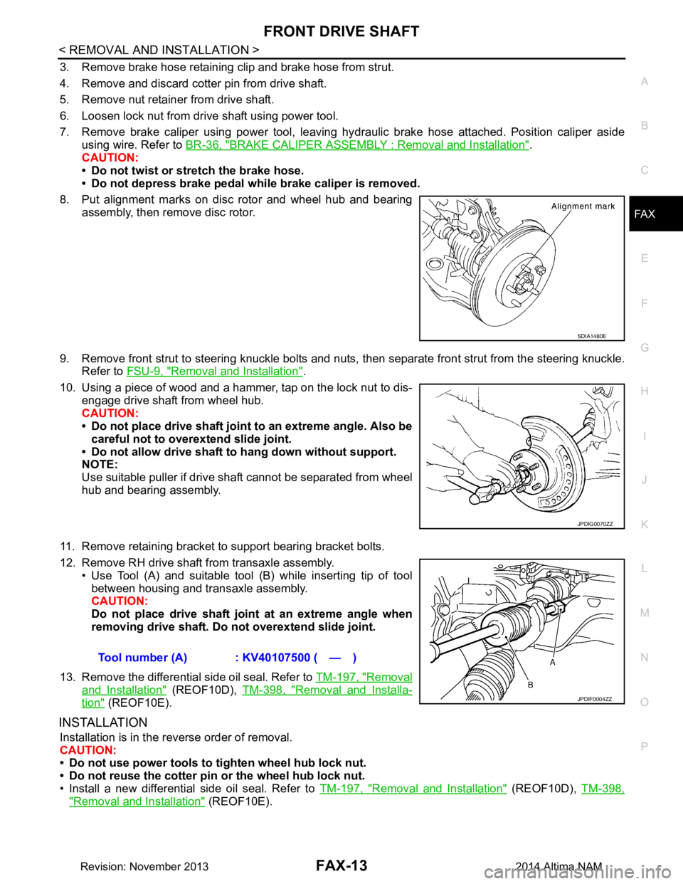
3. Remove brake hose retaining clip and brake hose from strut.
4. Remove and discard cotter pin from drive shaft.
5. Remove nut retainer from drive shaft.
6. Loosen lock nut from drive shaft using power tool.
7. Remove brake caliper using power tool, leaving hy draulic brake hose attached. Position caliper aside
using wire. Refer to BR-36, "BRAKE CALIPER ASSEMBLY : Removal and Installation"
.
CAUTION:
• Do not twist or stretch the brake hose.
• Do not depress brake pedal while brake caliper is removed.
8. Put alignment marks on disc rotor and wheel hub and bearing assembly, then remove disc rotor.
9. Remove front strut to steering knuckle bolts and nuts, then separate front strut from the steering knuckle.
Refer to FSU-9, "Removal and Installation"
.
10. Using a piece of wood and a hammer, tap on the lock nut to dis- engage drive shaft from wheel hub.
CAUTION:
• Do not place drive shaft joint to an extreme angle. Also be careful not to over extend slide joint.
• Do not allow drive shaft to hang down without support.
NOTE:
Use suitable puller if drive shaft cannot be separated from wheel
hub and bearing assembly.
11. Remove retaining bracket to support bearing bracket bolts.
12. Remove RH drive shaft from transaxle assembly. • Use Tool (A) and suitable tool (B) while inserting tip of tool
between housing and transaxle assembly.
CAUTION:
Do not place drive shaft join t at an extreme angle when
removing drive shaft. Do not overextend slide joint.
13. Remove the differential side oil seal. Refer to TM-197, "Removal
and Installation" (REOF10D), TM-398, "Removal and Installa-
tion" (REOF10E).
INSTALLATION
Installation is in the reverse order of removal.
CAUTION:
• Do not use power tools to tighten wheel hub lock nut.
• Do not reuse the cotter pin or the wheel hub lock nut.
• Install a new differential side oil seal. Refer to TM-197, "Removal and Installation"
(REOF10D), TM-398,
"Removal and Installation" (REOF10E).
SDIA1480E
JPDIG0070ZZ
Tool number (A) : KV40107500 ( — )
JPDIF0004ZZ
Revision: November 20132014 Altima NAM