2014 NISSAN TEANA trunk release
[x] Cancel search: trunk releasePage 2827 of 4801

INL-6
< SYSTEM DESCRIPTION >
COMPONENT PARTS
IPDM E/RThe IPDM E/R activates the tail lamp relay based on inputs re-
ceived from the BCM via the CAN communication.
Push button ignition switch Provides ignition switch status to the BCM.
Door switches Provides door OPEN/CLOSED status to the BCM.
Combination switch
(lighting and turn signal switch) The combination switch (lighting and turn signal switch) provides
input to the BCM. The BCM then sends a tail lamp relay request
signal to the IPDM E/R via CAN communication to operate the il-
lumination system.
Trunk lamp switch and release solenoid
(trunk lamp switch) Provides trunk lamp switch OP
EN/CLOSED status to the BCM.
Power window and door lock/unlock switch RH Provides door lock/unlock position switch RH status to the BCM.
Main power window and door lock/unlock switch Provides door lock/unlock position switch LH status to the BCM.
Meter control switch
(illumination control switch) • Adjusts the illumination system and combination meter illumina-
tion brightness (with multiple illumination control).
• Only adjusts the combination meter illumination brightness
(with meter illumination control only).
Front door lock assembly LH (key cylinder switch) Provides front door lock assembly LH (key cylinder switch) door
lock/unlock switch position status to the BCM.
Revision: November 20132014 Altima NAMRevision: November 20132014 Altima NAM
Page 2889 of 4801
INL-68
< REMOVAL AND INSTALLATION >
TRUNK ROOM LAMP
TRUNK ROOM LAMP
Removal and InstallationINFOID:0000000009463904
WARNING:
Do not touch bulb while it is lit or right after being turned OFF. Burning may result.
CAUTION:
Do not touch glass surface of the bulb with bare ha nds or allow oil or grease to get on it to prevent
damage to bulb.
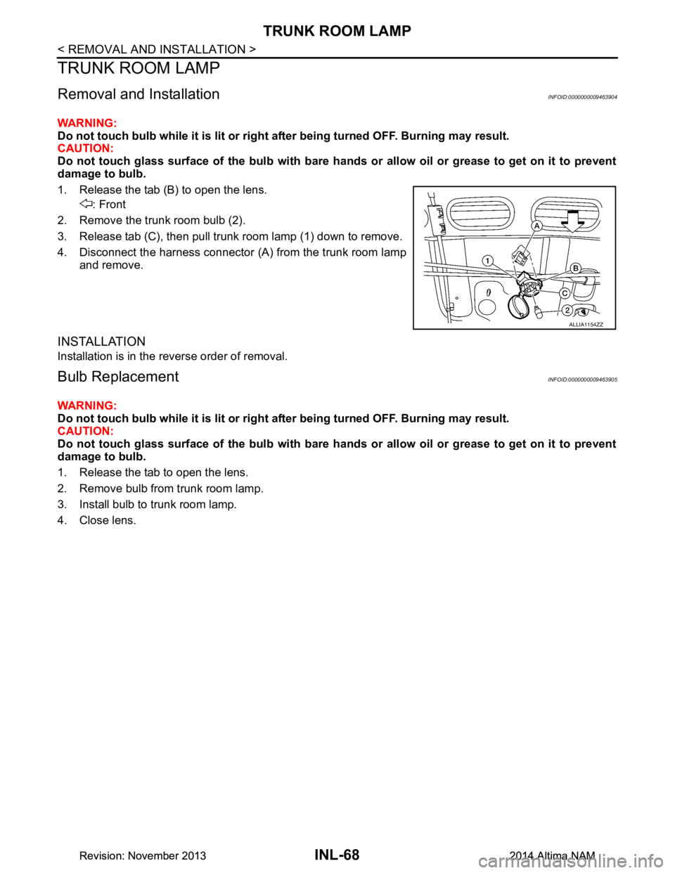
1. Release the tab (B) to open the lens. : Front
2. Remove the trunk room bulb (2).
3. Release tab (C), then pull trunk room lamp (1) down to remove.
4. Disconnect the harness connector (A ) from the trunk room lamp
and remove.
INSTALLATION
Installation is in the reverse order of removal.
Bulb ReplacementINFOID:0000000009463905
WARNING:
Do not touch bulb while it is lit or right after being turned OFF. Burning may result.
CAUTION:
Do not touch glass surface of the bulb with bare ha nds or allow oil or grease to get on it to prevent
damage to bulb.
1. Release the tab to open the lens.
2. Remove bulb from trunk room lamp.
3. Install bulb to trunk room lamp.
4. Close lens.
ALLIA1154ZZ
Revision: November 20132014 Altima NAMRevision: November 20132014 Altima NAM
Page 2924 of 4801
TRUNK ROOM TRIM & TRUNK LID FINISHERINT-33
< REMOVAL AND INSTALLATION >
C
D E
F
G H
I
K L
M A
B
INT
N
O P
TRUNK ROOM TRIM & TRUNK LID FINISHER
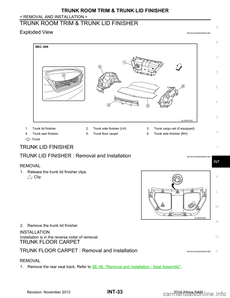
Exploded ViewINFOID:0000000009461364
TRUNK LID FINISHER
TRUNK LID FINISHER : Re moval and InstallationINFOID:0000000009461365
REMOVAL
1. Release the trunk lid finisher clips.
: Clip
2. Remove the trunk lid finisher.
INSTALLATION
Installation is in the reverse order of removal.
TRUNK FLOOR CARPET
TRUNK FLOOR CARPET : Re moval and InstallationINFOID:0000000009461366
REMOVAL
1. Remove the rear seat back. Refer to SE-36, "Removal and Installation - Seat Assembly".
1. Trunk lid finisher 2. Trunk side finisher (LH) 3. Trunk cargo net (if equipped)
4. Trunk rear finisher 5. Trunk floor carpet 6. Trunk side finisher (RH)
Front
ALJIA0915ZZ
ALJIA0919ZZ
Revision: November 20132014 Altima NAM
Page 2926 of 4801
TRUNK ROOM TRIM & TRUNK LID FINISHERINT-35
< REMOVAL AND INSTALLATION >
C
D E
F
G H
I
K L
M A
B
INT
N
O P
INSTALLATION
Installation is in the reverse order of removal.
TRUNK REAR FINISHER
TRUNK REAR FINISHER : Removal and InstallationINFOID:0000000009461369
REMOVAL
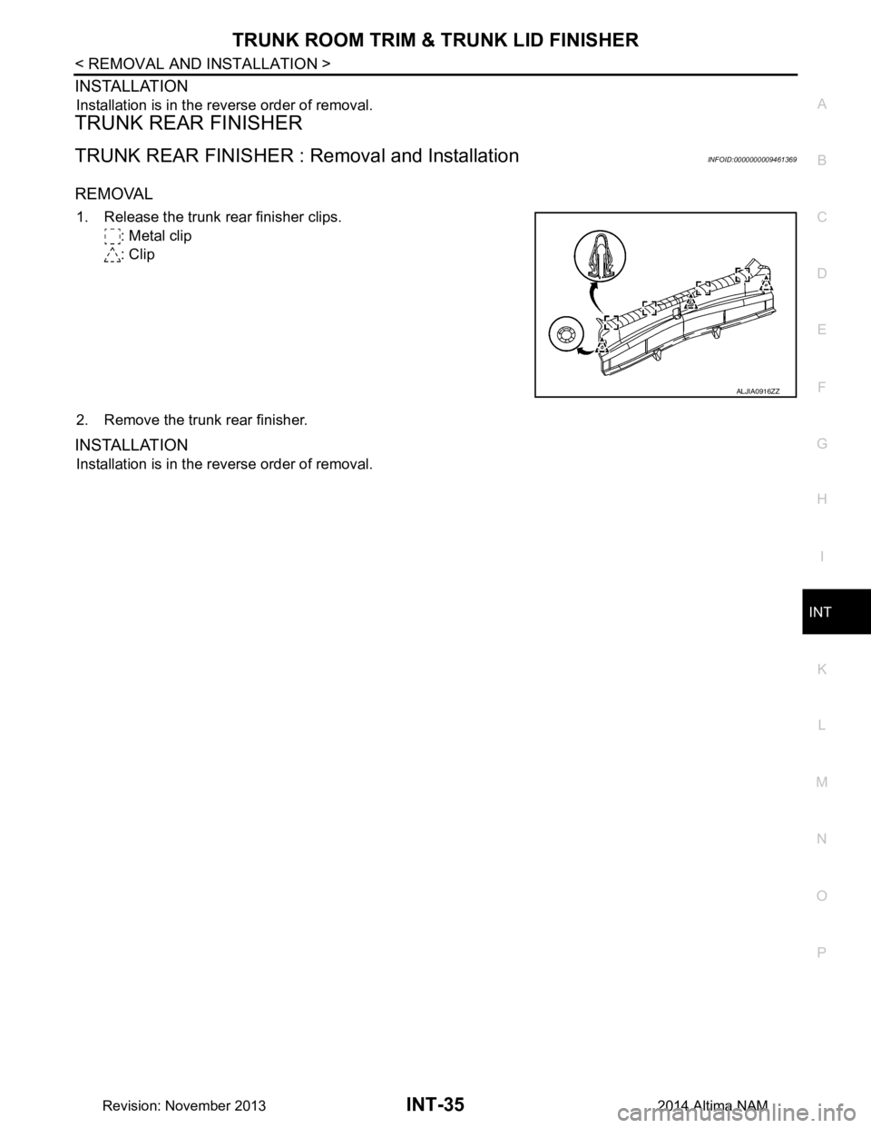
1. Release the trunk rear finisher clips.
: Metal clip
: Clip
2. Remove the trunk rear finisher.
INSTALLATION
Installation is in the reverse order of removal.
ALJIA0916ZZ
Revision: November 20132014 Altima NAM
Page 3257 of 4801

MWI-2
Wiring Diagram .......................................................30
METER ...............................................................32
Wiring Diagram .................................................... ...32
BASIC INSPECTION ...................................51
DIAGNOSIS AND REPAIR WORKFLOW ...... ...51
Work flow ............................................................. ...51
DTC/CIRCUIT DIAGNOSIS ...................... ...53
U1000 CAN COMM CIRCUIT ......................... ...53
DTC Logic ............................................................ ...53
Diagnosis Procedure .............................................53
U1010 CONTROL UNIT (CAN) .........................54
Description ........................................................... ...54
DTC Logic ...............................................................54
Diagnosis Procedure ..............................................54
B2205 VEHICLE SPEED ...................................55
Description ........................................................... ...55
DTC Logic ...............................................................55
Diagnosis Procedure .............................................55
B2267 ENGINE SPEED .....................................56
Description ........................................................... ...56
DTC Logic ...............................................................56
Diagnosis Procedure ..............................................56
B2268 WATER TEMP ........................................57
Description ........................................................... ...57
DTC Logic ...............................................................57
Diagnosis Procedure ..............................................57
POWER SUPPLY AND GROUND CIRCUIT .....58
COMBINATION METER ........................................ ...58
COMBINATION METER : Diagnosis Procedure ....58
BCM (BODY CONTROL MODULE) ...................... ...58
BCM (BODY CONTROL MODULE) : Diagnosis
Procedure ............................................................ ...
58
IPDM E/R (INTELLIGENT POWER DISTRIBU-
TION MODULE ENGINE ROOM) .......................... ...
59
IPDM E/R (INTELLIGENT POWER DISTRIBU-
TION MODULE ENGINE ROOM) : Diagnosis Pro-
cedure .................................................................. ...
59
FUEL LEVEL SENSOR SIGNAL CIRCUIT .......61
Description ........................................................... ...61
Component Function Check ...................................61
Diagnosis Procedure .............................................61
Component Inspection ............................................62
PARKING BRAKE SWITCH SIGNAL CIR-
CUIT ................................................................ ...
63
Description ........................................................... ...63
Component Function Check ...................................63
Diagnosis Procedure ..............................................63
Component Inspection ......................................... ...63
WASHER FLUID LEVEL SWITCH CIRCUIT ....64
Description ........................................................... ...64
Diagnosis Procedure ...............................................64
Component Inspection ............................................64
AMBIENT SENSOR SIGNAL CIRCUIT ............66
Description ........................................................... ...66
Component Function Check ...................................66
Diagnosis Procedure ...............................................66
Component Inspection ............................................67
METER CONTROL SWITCH SIGNAL CIR-
CUIT ................................................................ ...
68
Diagnosis Procedure ............................................ ...68
Component Inspection ............................................69
STEERING SWITCH ..........................................70
Description ........................................................... ...70
Diagnosis Procedure ...............................................70
Component Inspection ............................................70
SYMPTOM DIAGNOSIS ............................72
THE FUEL GAUGE INDICATOR DOES NOT
OPERATE ....................................................... ...
72
Description ........................................................... ...72
Diagnosis Procedure ...............................................72
THE METER CONTROL SWITCH IS INOPER-
ATIVE .............................................................. ...
73
Description ........................................................... ...73
Diagnosis Procedure ...............................................73
THE OIL PRESSURE WARNING CONTIN-
UES DISPLAYING, OR DOES NOT DISPLAY ...
74
Description ........................................................... ...74
Diagnosis Procedure ...............................................74
THE PARKING BRAKE RELEASE WARNING
CONTINUES DISPLAYING, OR DOES NOT
DISPLAY ......................................................... ...
75
Description ........................................................... ...75
Diagnosis Procedure ...............................................75
THE LOW WASHER FLUID WARNING CON-
TINUES DISPLAYING, or DOES NOT DIS-
PLAY ............................................................... ...
76
Description ........................................................... ...76
Diagnosis Procedure ...............................................76
THE DOOR OPEN WARNING CONTINUES
DISPLAYING, OR DOES NOT DISPLAY ...... ...
77
Description ........................................................... ...77
Diagnosis Procedure ...............................................77
THE TRUNK OPEN WARNING CONTINUES
DISPLAYING, OR DOES NOT DISPLAY ...... ...
78
Description ........................................................... ...78
Diagnosis Procedure ...............................................78
Revision: November 20132014 Altima NAMRevision: November 20132014 Altima NAM
Page 3268 of 4801
MWI
SYSTEMMWI-13
< SYSTEM DESCRIPTION >
C
D E
F
G H
I
J
K L
M B
A
O P
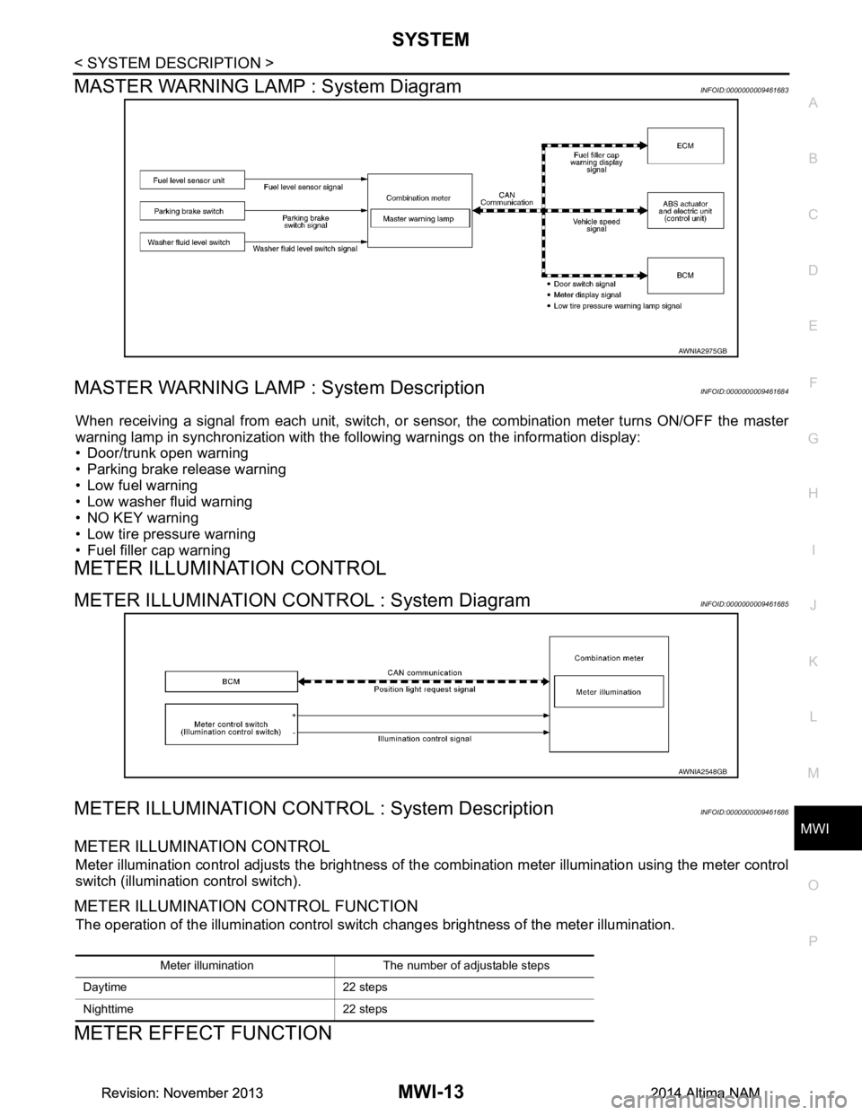
MASTER WARNING LAMP : System DiagramINFOID:0000000009461683
MASTER WARNING LAMP : System DescriptionINFOID:0000000009461684
When receiving a signal from each unit, switch, or s ensor, the combination meter turns ON/OFF the master
warning lamp in synchronization with the following warnings on the information display:
• Door/trunk open warning
• Parking brake release warning
• Low fuel warning
• Low washer fluid warning
• NO KEY warning
• Low tire pressure warning
• Fuel filler cap warning
METER ILLUMINATION CONTROL
METER ILLUMINATION CONTROL : System DiagramINFOID:0000000009461685
METER ILLUMINATION CONTROL : System DescriptionINFOID:0000000009461686
METER ILLUMINATION CONTROL
Meter illumination control adjusts the brightness of the combination meter illumination using the meter control
switch (illumination control switch).
METER ILLUMINATION CONTROL FUNCTION
The operation of the illumination control switch changes brightness of the meter illumination.
METER EFFECT FUNCTION
AWNIA2975GB
AWNIA2548GB
Meter illumination The number of adjustable steps
Daytime 22 steps
Nighttime 22 steps
Revision: November 20132014 Altima NAMRevision: November 20132014 Altima NAM
Page 3270 of 4801
MWI
SYSTEMMWI-15
< SYSTEM DESCRIPTION >
C
D E
F
G H
I
J
K L
M B
A
O P
Engine-start effect exits when any of the above operat ional conditions is cancelled during the engine-start
effect.
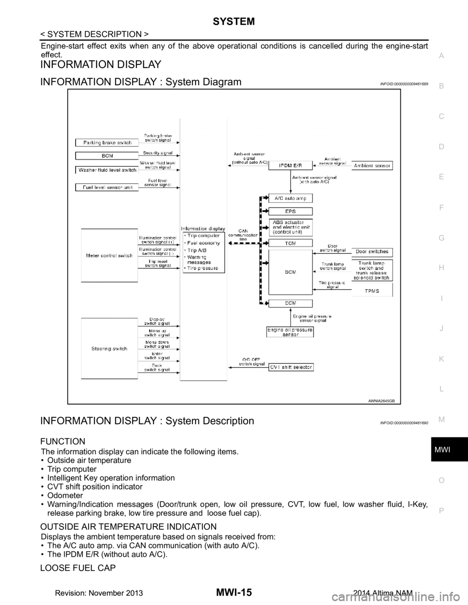
INFORMATION DISPLAY
INFORMATION DISPLAY : System DiagramINFOID:0000000009461689
INFORMATION DISPLAY : System DescriptionINFOID:0000000009461690
FUNCTION
The information display can indicate the following items.
• Outside air temperature
• Trip computer
• Intelligent Key operation information
• CVT shift position indicator
• Odometer
• Warning/Indication messages (Door/trunk open, low oil pressure, CVT, low fuel, low washer fluid, I-Key,
release parking brake, low tire pressure and loose fuel cap).
OUTSIDE AIR TEMPERATURE INDICATION
Displays the ambient temperature based on signals received from:
• The A/C auto amp. via CAN communication (with auto A/C).
• The IPDM E/R (without auto A/C).
LOOSE FUEL CAP
AWNIA2645GB
Revision: November 20132014 Altima NAMRevision: November 20132014 Altima NAM
Page 3271 of 4801

MWI-16
< SYSTEM DESCRIPTION >
SYSTEM
The LOOSE FUEL CAP message will display in the information display when the fuel-filler cap is not tightened
correctly. The message will turn off as soon as the EC M detects the fuel-filler cap is properly tightened. The
ECM provides a loose fuel cap signal to the combination meter via CAN communication.
LOW TIRE PRESSURE WARNING
This warning appears when the BCM detects low inflati on pressure or a system malfunction. The BCM sends
a signal to the combination meter via CAN communication to illuminate the low tire pressure warning lamp. In
addition, a warning message will be displayed in the vehicle information display.
DOOR OPEN WARNING
This warning appears when the ignition switch is ON and the door is open. The BCM receives a door switch
signal from the door open door switch. The BCM sends t he door switch signal to the combination meter via
CAN communication lines.
TRUNK OPEN WARNING
This warning appears when the ignition switch is ON and the trunk is opened. The BCM receives a trunk lamp
switch signal from the trunk lamp switch. The BCM s ends the trunk lamp switch signal to the combination
meter via CAN communication.
LOW FUEL WARNING
This warning appears when the fuel level in the fuel tank is less than approximately 4 US gal (15 L, 3.3 Imp
gal). A variable resistor signal is supplied to the combi nation meter from the fuel level sensor unit to determine
the amount of fuel in the fuel tank.
LOW WINDSHIELD WASHER FLUID WARNING
When the windshield washer fluid level is low, the was her fluid level switch provides a ground signal to the
combination meter and the warning is displayed. Once fluid is added, the switch opens and the warning is no
longer displayed.
RELEASE PARKING BRAKE WARNING
When the parking brake is applied, the parking brake switch provides a ground signal to the combination
meter. When the vehicle speed is greater than 4 MPH (7 km/h), the message is displayed and the warning
chime sounds.
SHIFT POSITION INDICATOR
Displays the position of the shift selector based on signals received from TCM via CAN communication.
LOW OIL PRESSURE WARNING
The low oil pressure warning appears in the information display when the combination meter receives a low
engine oil pressure signal from the ECM via CAN communication.
WARNING CHECK INDICATION
The combination meter can cause an interrupt on the information display to indicate a warning, based on sig-
nals received from each unit and switch.
Refer to Owner’s Manual for additional information display items.
COMPASS
COMPASS : DescriptionINFOID:0000000009461691
DESCRIPTION
With the ignition switch in the ON position, and the mode (N) switch
ON, the compass display will indicate the direction the vehicle is
heading.
Vehicle direction is displayed as follows:
• N: north
• E: east
• S: south
•W: west
LKIA0447E
Revision: November 20132014 Altima NAMRevision: November 20132014 Altima NAM