Page 908 of 4801

DLK-140
< DTC/CIRCUIT DIAGNOSIS >
TRUNK LID OPENER ACTUATOR
TRUNK LID OPENER ACTUATOR
DescriptionINFOID:0000000009461885
Performs trunk lid open with signal from BCM.
Component Function CheckINFOID:0000000009461886
1.CHECK FUNCTION
1. Perform Active Test TRUNK/GLASS HATCH with CONSULT.
2. Touch “OPEN” and check that trunk lid opens.
Is the inspection result normal?
YES >> Trunk lid opener actuator is OK.
NO >> Refer to DLK-140, "Diagnosis Procedure"
.
Diagnosis ProcedureINFOID:0000000009461887
Regarding Wiring Diagram information, refer to DLK-77, "Wiring Diagram".
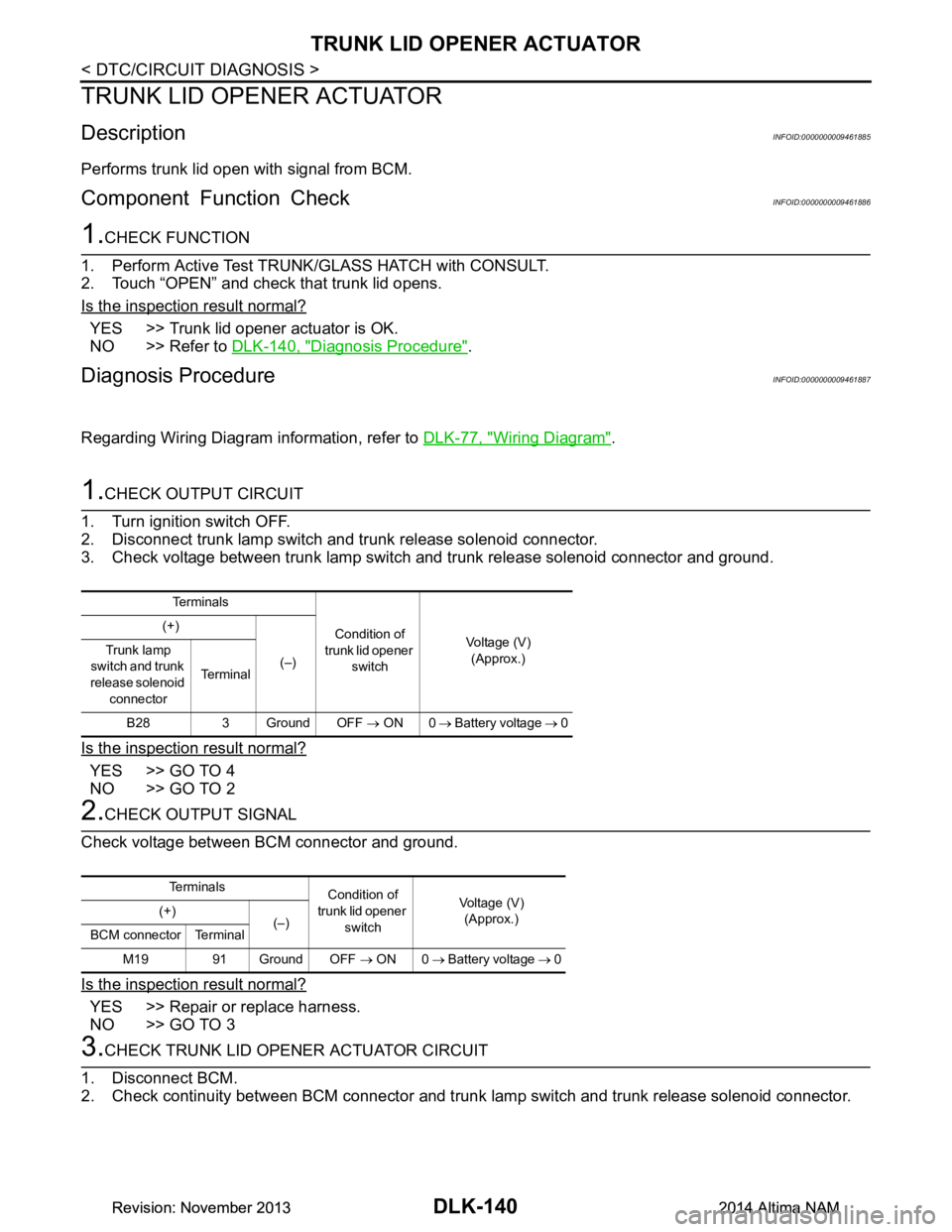
1.CHECK OUTPUT CIRCUIT
1. Turn ignition switch OFF.
2. Disconnect trunk lamp switch and trunk release solenoid connector.
3. Check voltage between trunk lamp switch and trunk release solenoid connector and ground.
Is the inspection result normal?
YES >> GO TO 4
NO >> GO TO 2
2.CHECK OUTPUT SIGNAL
Check voltage between BCM connector and ground.
Is the inspection result normal?
YES >> Repair or replace harness.
NO >> GO TO 3
3.CHECK TRUNK LID OPENER ACTUATOR CIRCUIT
1. Disconnect BCM.
2. Check continuity between BCM connector and trunk la mp switch and trunk release solenoid connector.
Te r m i n a l s
Condition of
trunk lid opener switch Voltage (V)
(Approx.)
(+)
(–)
Trunk lamp
switch and trunk
release solenoid connector Te r m i n a l
B28 3 Ground OFF → ON 0 → Battery voltage → 0
Te r m i n a l s
Condition of
trunk lid opener switch Voltage (V)
(Approx.)
(+)
(–)
BCM connector Terminal
M19 91 Ground OFF → ON 0 → Battery voltage → 0
Revision: November 20132014 Altima NAMRevision: November 20132014 Altima NAM
Page 909 of 4801
TRUNK LID OPENER ACTUATORDLK-141
< DTC/CIRCUIT DIAGNOSIS >
C
D E
F
G H
I
J
L
M A
B
DLK
N
O P
3. Check continuity between BCM connector and ground.
Is the inspection result normal?
YES >> Replace BCM. Refer to BCS-80, "Removal and Installation".
NO >> Repair or replace harness.
4.CHECK TRUNK LID OPENER GROUND CIRCUIT
Check continuity between trunk lamp switch and trunk release solenoid connector and ground.
Is the inspection result normal?
YES >> Replace trunk lamp switch and trunk release solenoid.
NO >> Repair or replace harness.
BCM connector Terminal Trunk lamp switch and
trunk release solenoid
connector Terminal Continuity
M19 91 B28 3 Yes
BCM connector Terminal Continuity M19 91 Ground No
Trunk lamp switch and trunk release solenoid connector Terminal Continuity
B28 2 Ground Yes
Revision: November 20132014 Altima NAMRevision: November 20132014 Altima NAM
Page 914 of 4801

DLK-146
< DTC/CIRCUIT DIAGNOSIS >
INTELLIGENT KEY BATTERY AND FUNCTION
INTELLIGENT KEY BATTERY AND FUNCTION
DescriptionINFOID:0000000009461895
The following functions are available when having and carrying the Intelligent Key.
• Door lock/unlock
• Trunk open
Remote control entry function and panic alarm functi on are available when operating the remote buttons.
Component Function CheckINFOID:0000000009461896
NOTE:
The Signal Tech II Tool (J-50190) can be used to perform the following functions. Refer to the Signal Tech II
User Guide for additional information.
• Check Intelligent Key relative signal strength
• Confirm vehicle Intelligent Key antenna signal strength
1.CHECK FUNCTION
With CONSULT
Check remote keyless entry receiver RKE OP E COUN1 in Data Monitor mode with CONSULT.
Is the inspection result normal?
YES >> Intelligent Key is OK.
NO >> Refer to DLK-146, "Diagnosis Procedure"
.
Diagnosis ProcedureINFOID:0000000009461897
NOTE:
The Signal Tech II Tool (J-50190) can be used to perform the following functions. Refer to the Signal Tech II
User Guide for additional information.
• Check Intelligent Key relative signal strength
• Confirm vehicle Intelligent Key antenna signal strength
1.CHECK INTELLIGENT KEY FUNCTION
Check Intelligent Key function using Signal Tech II Tool J-50190 or
Remote Keyless Entry Tester J-43241 (shown).
Does the test pass?
YES >> Intelligent Key is OK.
NO >> GO TO 2
2. CHECK INTELLIGENT KEY COMPONENTS
1. Release the lock knob at the back of the In telligent Key and remove the mechanical key.
Monitor item Condition
RKE OPE COUN1 Check that the numerical value is changing while operating with the Intelligent Key.
LEL946A
Revision: November 20132014 Altima NAMRevision: November 20132014 Altima NAM
Page 974 of 4801

DLK-206
< REMOVAL AND INSTALLATION >
TRUNK LID
TRUNK LID
TRUNK LID ASSEMBLY
TRUNK LID ASSEMBLY : Exploded ViewINFOID:0000000009461953
TRUNK LID ASSEMBLY : Removal and InstallationINFOID:0000000009461954
CAUTION:
• Use two people when removing or installing trunk lid assembly due to its heavy weight.
• Use protective tape or shop cloths to protect surrounding components from damage during removal
and installation of trunk lid assembly.
REMOVAL
1. Remove trunk lid finisher (if equipped). Refer to INT-33, "TRUNK LID FINISHER : Removal and Installa-
tion".
1. Trunk lid hinge (LH/RH) 2. Torsion bar (LH/RH) 3. Torsion bar clips
4. Trunk lid finisher (if equipped) 5. Emergency release lever handle 6. Emergency release lever clip
7. Emergency release lever cable 8. Trunk lamp switch and trunk re- lease solenoid9. Trunk lid bumpers
10. License plate finisher 11. Rear spoiler (if equipped) 12. Trunk lid
13. Weatherstrip A. Clip Clip
ALKIA2718ZZ
Revision: November 20132014 Altima NAMRevision: November 20132014 Altima NAM
Page 975 of 4801
TRUNK LIDDLK-207
< REMOVAL AND INSTALLATION >
C
D E
F
G H
I
J
L
M A
B
DLK
N
O P
2. Disconnect the harness connectors in the trunk lid assembly (1) and remove the harness clips (A) then pull out harness from the
trunk lid assembly (1).
3. Disconnect rear view camera (2) from rear washer tube (1) then release clip from the truck lid assembly (if necessary).
4. Remove the bolts (A) and the trunk lid assembly (1).
INSTALLATION
Installation is in the reverse order of removal.
CAUTION:
After installation, perform the trunk lid assembly adjustment procedure. Refer to DLK-208, "TRUNK
LID ASSEMBLY : Adjustment".
ALKIA2733ZZ
ALOIA0202ZZ
ALKIA2734ZZ
Revision: November 20132014 Altima NAMRevision: November 20132014 Altima NAM
Page 977 of 4801

TRUNK LIDDLK-209
< REMOVAL AND INSTALLATION >
C
D E
F
G H
I
J
L
M A
B
DLK
N
O P
If the clearance and the surface height are out of specific ation, adjust them according to the adjustment proce-
dures.
Unit: mm (in)
LONGITUDINAL CLEARANCE
Trunk Lid Removed From Hinge
1. Loosen the trunk lid to hinge bolts.
2. Move the trunk lid so that the clearance m easurements are within specifications provided.
3. Tighten the trunk lid to hinge bolts.
Trunk Lid Hinge Removed From Vehicle
1. Remove the rear parcel shelf trim. Refer to INT-26, "Removal and Installation".
2. Loosen the hinge to parcel shelf bolts.
3. Move the trunk lid so that the clearance m easurements are within specifications provided.
4. Tighten the hinge to parcel shelf bolts.
5. Install the rear parcel shelf trim. Refer to INT-26, "Removal and Installation"
.
SURFACE HEIGHT ADJUSTMENT
1. Loosen the bumper rubber.
2. Loosen the striker bolts.
3. Lift up the trunk lid approx. 100 - 150 mm (3.94 - 5.91 in) height then close it lightly. Make sure it engages
firmly with the trunk lid closed.
4. Tighten the trunk lid striker.
TRUNK LID HINGE
TRUNK LID HINGE : Remo val and InstallationINFOID:0000000009461956
REMOVAL
1. Remove trunk lid assembly. Refer to DLK-206, "TRUNK LID ASSEMBLY : Removal and Installation".
2. Remove torsion bar. Refer to DLK-210, "TORSION BAR : Removal and Installation"
.
3. Remove rear parcel shelf finisher. Refer to INT-26, "Removal and Installation"
.
4. Release rear washer tube clips (RH only) (if equipped).
5. Remove trunk lid hinge bolts (body side) and then trunk lid hinge.
INSTALLATION
Installation is in the reverse order of removal.
CAUTION:
• Check trunk lid open/close, lock/un lock operation after installation.
• After installation, perform the trunk li d assembly adjustment procedure. Refer to DLK-208, "TRUNK
LID ASSEMBLY : Adjustment".
Section Item Measurement Standard Parallelism (MAX) Right/Left
Difference (MAX)
A – A E Clearance 3.5
± 1.0 (0.14 ± 0.04) 1.4 (0.06) 1.4 (0.06)
F Surface height 0.0 ± 1.0 (0.00 ± 0.04) 1.4 (0.06) 1.4 (0.06)
B – B G Clearance 3.5
± 1.0 (0.14 ± 0.04) 1.4 (0.06) 1.4 (0.06)
H Surface height 0.0 ± 1.0 (0.00 ± 0.04) 1.4 (0.06) 1.4 (0.06)
C – C J Clearance 4.0 ± 1.5 (0.16 ± 0.06) — 2.0 (0.08)
D – D K Clearance 6.0 ± 2.0 (0.24 ± 0.08) 2.0 (0.08) —
Revision: November 20132014 Altima NAMRevision: November 20132014 Altima NAM
Page 978 of 4801
DLK-210
< REMOVAL AND INSTALLATION >
TRUNK LID
• Check trunk lid hinge rotating point for poor lubrication. If
necessary, apply a suitable multi-purpose grease.
: Grease
TORSION BAR
TORSION BAR : Remova l and InstallationINFOID:0000000009461957
REMOVAL
1. Remove torsion bar clips.
2. Support the trunk lid assembly using a suitable tool. WARNING:
Bodily injury may occur if hood assembly is not supported properly when removing hood assem-
bly.
3. Lift torsion bar (1) using a suitable tool (A) as shown to remove.
NOTE:
The suitable tool specifications are as shown.
INSTALLATION
Installation is in the reverse order of removal.
CAUTION:
After installation check the trunk li d open/close, lock/unlock operation.
TRUNK LAMP SWITCH AND TRUNK RELEASE SOLENOID
TRUNK LAMP SWITCH AND TRUNK RELEASE SOLENOID : Removal and Installa-
tion
INFOID:0000000009461958
REMOVAL
JMKIA8127ZZ
JMKIA8128ZZ
PIIB3774J
Revision: November 20132014 Altima NAMRevision: November 20132014 Altima NAM
Page 979 of 4801

TRUNK LIDDLK-211
< REMOVAL AND INSTALLATION >
C
D E
F
G H
I
J
L
M A
B
DLK
N
O P
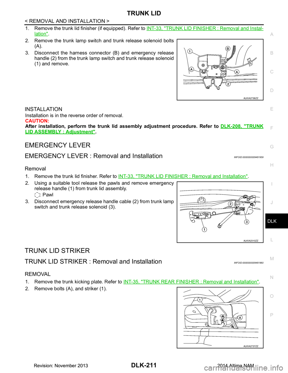
1. Remove the trunk lid finisher (if equipped). Refer to INT-33, "TRUNK LID FINISHER : Removal and Instal-
lation".
2. Remove the trunk lamp switch and trunk release solenoid bolts (A).
3. Disconnect the harness connector (B) and emergency release handle (2) from the trunk lamp switch and trunk release solenoid
(1) and remove.
INSTALLATION
Installation is in the reverse order of removal.
CAUTION:
After installation, perform the trunk lid assembly adjustment procedure. Refer to DLK-208, "TRUNK
LID ASSEMBLY : Adjustment".
EMERGENCY LEVER
EMERGENCY LEVER : Removal and InstallationINFOID:0000000009461959
Removal
1. Remove the trunk lid finisher. Refer to INT-33, "TRUNK LID FINISHER : Removal and Installation".
2. Using a suitable tool release the pawls and remove emergency release handle (1) from trunk lid assembly.
: Pawl
3. Disconnect emergency release handle cable (2) from trunk lamp switch and trunk release solenoid (3).
TRUNK LID STRIKER
TRUNK LID STRIKER : Re moval and InstallationINFOID:0000000009461960
REMOVAL
1. Remove the trunk kicking plate. Refer to INT-35, "TRUNK REAR FINISHER : Removal and Installation".
2. Remove bolts (A), and striker (1).
ALKIA2736ZZ
ALKIA2310ZZ
ALKIA2737ZZ
Revision: November 20132014 Altima NAMRevision: November 20132014 Altima NAM