Page 983 of 4801

FUEL FILLER LID OPENERDLK-215
< REMOVAL AND INSTALLATION >
C
D E
F
G H
I
J
L
M A
B
DLK
N
O P
6. Remove trunk side finisher (LH). Refer to INT-34, "TRUNK SIDE FINISHER : Removal and Installation".
7. Remove fuel filler lid opener cable from fuel filler lid lock assembly. Refer to DLK-215, "FUEL FILLER LID
LOCK : Removal and Installation".
8. Disengage each harness protector (1), and then remove fuel filler lid opener cable (2).
INSTALLATION
Installation is in the reverse order of removal.
CAUTION:
After installation, check fuel filler li d assembly open/close, lock/unlock operation.
FUEL FILLER LID LOCK
FUEL FILLER LID LOCK : Removal and InstallationINFOID:0000000009461964
REMOVAL
1. Fully open fuel filler lid.
2. Insert a suitable tool (A) as shown into bottom of fuel filler lock assembly(1).
3. Release lower pawls (A) using a suitable tool and remove fuel filler lid lock assembly (1) from opening.
CAUTION:
Be careful not to damage gasket (2) when removing.
JMKIA5720ZZ
ALKIA2731ZZ
JMKIA8138ZZ
Revision: November 20132014 Altima NAMRevision: November 20132014 Altima NAM
Page 994 of 4801
DLK-226
< REMOVAL AND INSTALLATION >
TRUNK LID OPENER CANCEL SWITCH
TRUNK LID OPENER CANCEL SWITCH
Removal and InstallationINFOID:0000000009461978
REMOVAL
1. Remove the glove box assembly. Refer to IP-22, "Removal and Installation".
2. Release pawls and remove the trunk cancel switch.
INSTALLATION
Installation is in the reverse order of removal.
Revision: November 20132014 Altima NAMRevision: November 20132014 Altima NAM
Page 995 of 4801
TRUNK LID OPENER SWITCHDLK-227
< REMOVAL AND INSTALLATION >
C
D E
F
G H
I
J
L
M A
B
DLK
N
O P
TRUNK LID OPENER SWITCH
Removal and InstallationINFOID:0000000009461979
REMOVAL
1. Remove the instrument lower panel LH. Refer to IP-21, "Removal and Installation".
2. Remove screws (A) that retain the upper switch carrier (1) to the instrument lower panel LH (2).
3. Release upper tab (B) and lower tab (C) using a suitable tool (A), then remove the trunk open switch (1) from the upper switch
carrier.
(1) Trunk opener switch
(2) VDC switch
(3) Heated steering wheel switch (if equipped)
(4) Blank
INSTALLATION
Installation is in the reverse order of removal.
ALKIA2729ZZ
ALOIA0144ZZ
Revision: November 20132014 Altima NAMRevision: November 20132014 Altima NAM
Page 996 of 4801
DLK-228
< REMOVAL AND INSTALLATION >
TRUNK OPENER REQUEST SWITCH
TRUNK OPENER REQUEST SWITCH
Removal and InstallationINFOID:0000000009461980
REMOVAL
1. Remove the license plate lamp finisher. Refer to EXT-37, "Removal and Installation".
2. Release the pawls and remove the trunk opener request switch (1).
: Pawl
INSTALLATION
Installation is in the reverse order of removal.
ALKIA2722ZZ
Revision: November 20132014 Altima NAMRevision: November 20132014 Altima NAM
Page 2401 of 4801

LICENSE PLATE LAMPEXL-135
< REMOVAL AND INSTALLATION >
C
D E
F
G H
I
J
K
M A
B
EXL
N
O P
LICENSE PLATE LAMP
Removal and InstallationINFOID:0000000009463633
REMOVAL
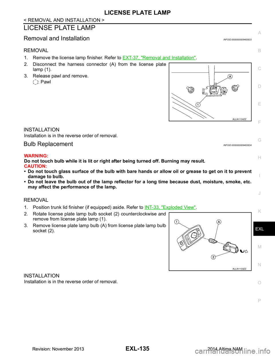
1. Remove the license lamp finisher. Refer to EXT-37, "Removal and Installation".
2. Disconnect the harness connector (A) from the license plate lamp (1).
3. Release pawl and remove. : Pawl
INSTALLATION
Installation is in the reverse order of removal.
Bulb ReplacementINFOID:0000000009463634
WARNING:
Do not touch bulb while it is lit or right after being turned off. Burning may result.
CAUTION:
• Do not touch glass surface of the bulb with bare hand s or allow oil or grease to get on it to prevent
damage to bulb.
• Do not leave the bulb out of the lamp reflector fo r a long time because dust, moisture, smoke, etc.
may affect the performance of the lamp.
REMOVAL
1. Position trunk lid finisher (if equipped) aside. Refer to INT-33, "Exploded View".
2. Rotate license plate lamp bulb socket (2) counterclockwise and remove from license plate lamp (1).
3. Remove license plate lamp bulb (A) from license plate lamp bulb socket (2).
INSTALLATION
Installation is in the reverse order of removal.
ALLIA1134ZZ
ALLIA1133ZZ
Revision: November 20132014 Altima NAMRevision: November 20132014 Altima NAM
Page 2452 of 4801

EXT-38
< REMOVAL AND INSTALLATION >
REAR SPOILER
REAR SPOILER
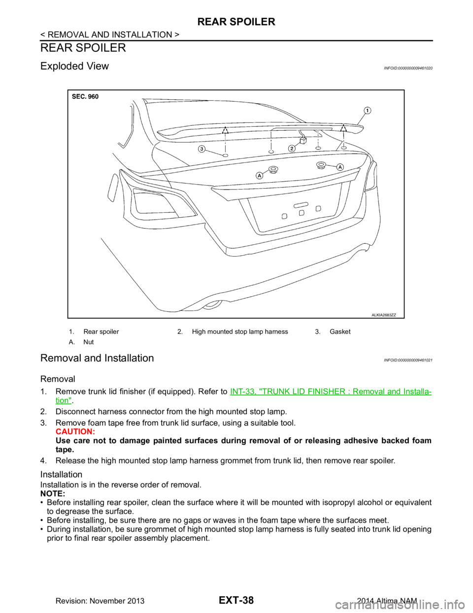
Exploded ViewINFOID:0000000009461020
Removal and InstallationINFOID:0000000009461021
Removal
1. Remove trunk lid finisher (if equipped). Refer to INT-33, "TRUNK LID FINISHER : Removal and Installa-
tion".
2. Disconnect harness connector from the high mounted stop lamp.
3. Remove foam tape free from trunk lid surface, using a suitable tool. CAUTION:
Use care not to damage painted surfaces during removal of or releasing adhesive backed foam
tape.
4. Release the high mounted stop lamp harness grommet from trunk lid, then remove rear spoiler.
Installation
Installation is in the reverse order of removal.
NOTE:
• Before installing rear spoiler, clean the surface w here it will be mounted with isopropyl alcohol or equivalent
to degrease the surface.
• Before installing, be sure there are no gaps or wa ves in the foam tape where the surfaces meet.
• During installation, be sure grommet of high mounted stop lamp harness is fully seated into trunk lid opening
prior to final rear spoiler assembly placement.
1. Rear spoiler 2. High mounted stop lamp harness 3. Gasket
A. Nut
ALKIA2683ZZ
Revision: November 20132014 Altima NAM
Page 2540 of 4801
GI-12
< HOW TO USE THIS MANUAL >
HOW TO READ WIRING DIAGRAMS
• ignition switch is “OFF”,
• doors, hood and trunk lid/back door are closed,
• pedals are not depressed, and
• parking brake is released.
MULTIPLE SWITCH
The continuity of multiple switch is described in two ways as shown below.
• The switch chart is used in schematic diagrams.
• The switch diagram is used in wiring diagrams.
SGI860
JSAIA0017GB
Revision: November 20132014 Altima NAMRevision: November 20132014 Altima NAM
Page 2826 of 4801

COMPONENT PARTSINL-5
< SYSTEM DESCRIPTION >
C
D E
F
G H
I
J
K
M A
B
INL
N
O P
SYSTEM DESCRIPTION
COMPONENT PARTS
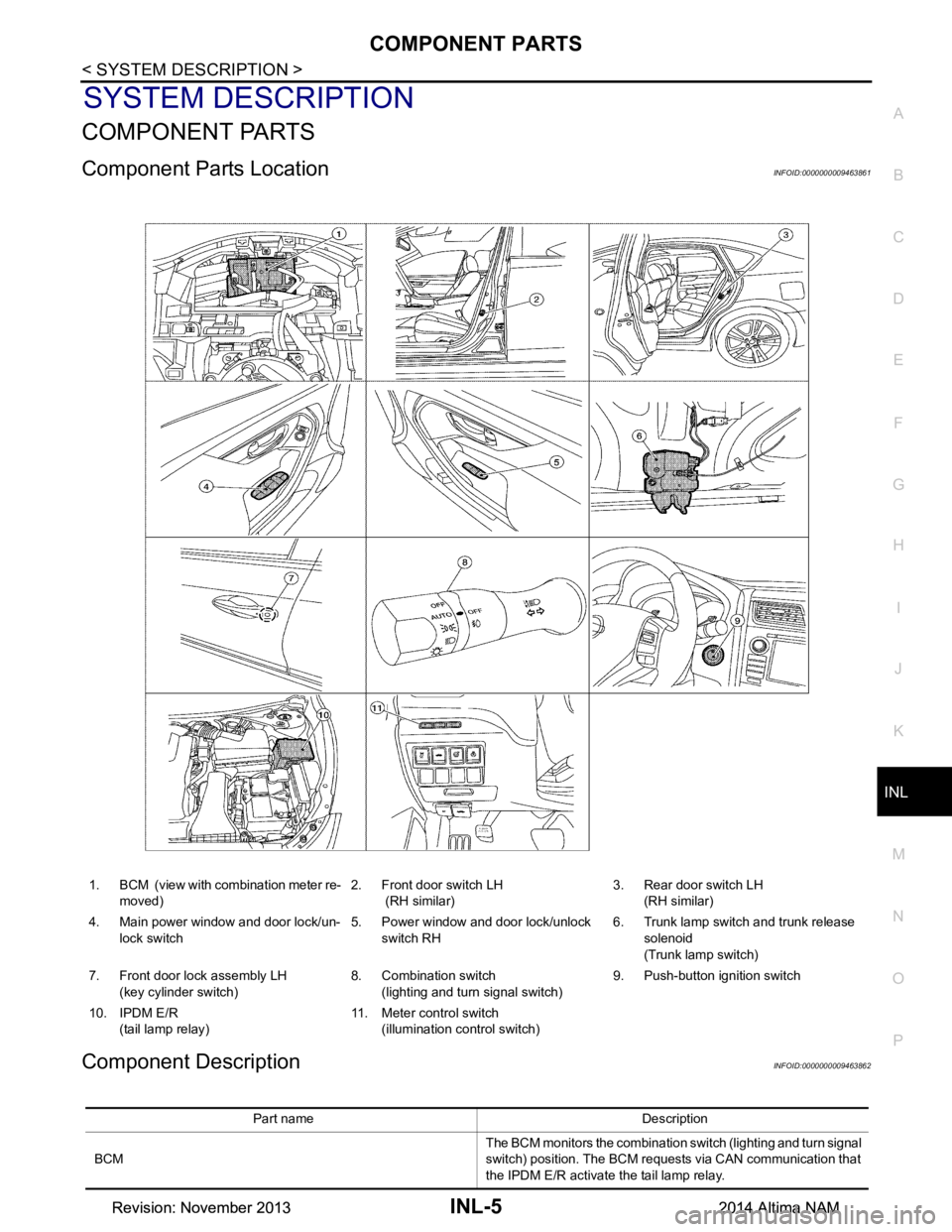
Component Parts LocationINFOID:0000000009463861
Component DescriptionINFOID:0000000009463862
1. BCM (view with combination meter re- moved) 2. Front door switch LH
(RH similar) 3. Rear door switch LH
(RH similar)
4. Main power window and door lock/un- lock switch 5. Power window and door lock/unlock
switch RH 6. Trunk lamp switch and trunk release
solenoid
(Trunk lamp switch)
7. Front door lock assembly LH (key cylinder switch) 8. Combination switch
(lighting and turn signal switch) 9. Push-button ignition switch
10. IPDM E/R (tail lamp relay) 11. Meter control switch
(illumination control switch)
Part name Description
BCM The BCM monitors the combination switch (lighting and turn signal
switch) position. The BCM requests via CAN communication that
the IPDM E/R activate the tail lamp relay.
Revision: November 20132014 Altima NAMRevision: November 20132014 Altima NAM