2014 NISSAN TEANA roof
[x] Cancel search: roofPage 3245 of 4801
SQUEAK AND RATTLE TROUBLE DIAGNOSESMIR-15
< SYMPTOM DIAGNOSIS >
C
D E
F
G H
I
J
K
M A
B
MIR
N
O P
INSTRUMENT PANEL
Most incidents are caused by contact and movement between:
1. Cluster lid A and the instrument panel
2. Acrylic lens and combination meter housing
3. Instrument panel to front pillar finisher
4. Instrument panel to windshield
5. Instrument panel pins
6. Wiring harnesses behind the combination meter
7. A/C defroster duct and duct joint
These incidents can usually be located by tapping or moving the components to duplicate the noise or by
pressing on the components while driving to stop the noi se. Most of these incidents can be repaired by apply-
ing felt cloth tape or silicone spray (in hard to reach areas). Urethane pads can be used to insulate wiring har-
ness.
CAUTION:
Do not use silicone spray to isolate a squeak or ra ttle. If you saturate the area with silicone, you will
not be able to recheck the repair.
CENTER CONSOLE
Components to pay attention to include:
1. Shift selector assembly cover to finisher
2. A/C control unit and cluster lid C
3. Wiring harnesses behind audio and A/C control unit
The instrument panel repair and isolation pr ocedures also apply to the center console.
DOORS
Pay attention to the:
1. Finisher and inner panel making a slapping noise
2. Inside handle escutcheon to door finisher
3. Wiring harnesses tapping
4. Door striker out of alignment causing a popping noise on starts and stops
Tapping or moving the components or pressing on them wh ile driving to duplicate the conditions can isolate
many of these incidents. You can usually insulate the ar eas with felt cloth tape or insulator foam blocks from
the NISSAN Squeak and Rattle Kit (J-50397) to repair the noise.
TRUNK
Trunk noises are often caused by a loose jack or loose items put into the trunk by the owner.
In addition look for:
1. Trunk lid bumpers out of adjustment
2. Trunk lid striker out of adjustment
3. The trunk lid torsion bars knocking together
4. A loose license plate or bracket
Most of these incidents can be repaired by adjusting, se curing or insulating the item(s) or component(s) caus-
ing the noise.
SUNROOF/HEADLINING
Noises in the sunroof/headlining area can often be traced to one of the following:
1. Sunroof lid, rail, linkage or seals making a rattle or light knocking noise
2. Sun visor shaft shaking in the holder
3. Front or rear windshield touching headlining and squeaking
Again, pressing on the components to stop the noise while duplicating the conditions can isolate most of these
incidents. Repairs usually consist of insulating with felt cloth tape.
OVERHEAD CONSOLE (FRONT AND REAR)
Overhead console noises are often caused by the cons ole panel clips not being engaged correctly. Most of
these incidents are repaired by pushing up on the c onsole at the clip locations until the clips engage.
In addition look for:
Revision: November 20132014 Altima NAMRevision: November 20132014 Altima NAM
Page 3439 of 4801
PG
INSPECTION AND ADJUSTMENTPG-7
< BASIC INSPECTION >
C
D E
F
G H
I
J
K L
B
A
O P
N
INSPECTION AND ADJUSTMENT
ADDITIONAL SERVICE WHEN REMOVI
NG BATTERY NEGATIVE TERMINAL
ADDITIONAL SERVICE WHEN REMOVING BATTERY NEGATIVE TERMINAL : Spe-
cial Repair Requirement
INFOID:0000000009460434
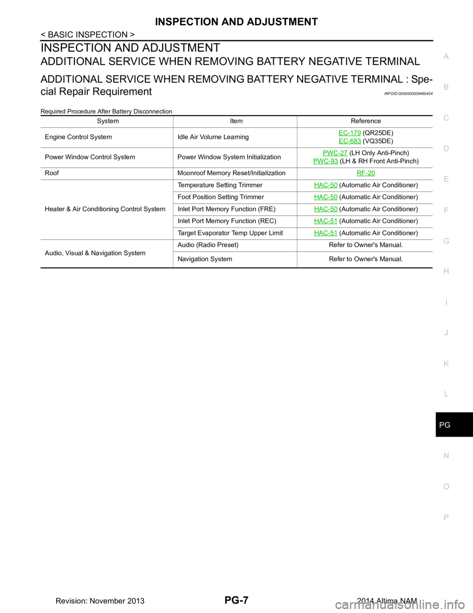
Required Procedure After Battery Disconnection
System Item Reference
Engine Control System Idle Air Volume Learning EC-179
(QR25DE)
EC-683
(VQ35DE)
Power Window Control System Power Window System Initialization PWC-27
(LH Only Anti-Pinch)
PWC-93
(LH & RH Front Anti-Pinch)
Roof Moonroof Memory Reset/Initialization RF-20
Heater & Air Conditioning Control SystemTemperature Setting Trimmer
HAC-50
(Automatic Air Conditioner)
Foot Position Setting Trimmer HAC-50
(Automatic Air Conditioner)
Inlet Port Memory Function (FRE) HAC-50
(Automatic Air Conditioner)
Inlet Port Memory Function (REC) HAC-51
(Automatic Air Conditioner)
Target Evaporator Temp Upper Limit HAC-51
(Automatic Air Conditioner)
Audio, Visual & Navigation System Audio (Radio Preset) Refer to Owner's Manual.
Navigation System Refer to Owner's Manual.
Revision: November 20132014 Altima NAM
Page 3489 of 4801
PG
HARNESSPG-57
< DTC/CIRCUIT DIAGNOSIS >
C
D E
F
G H
I
J
K L
B
A
O P
N
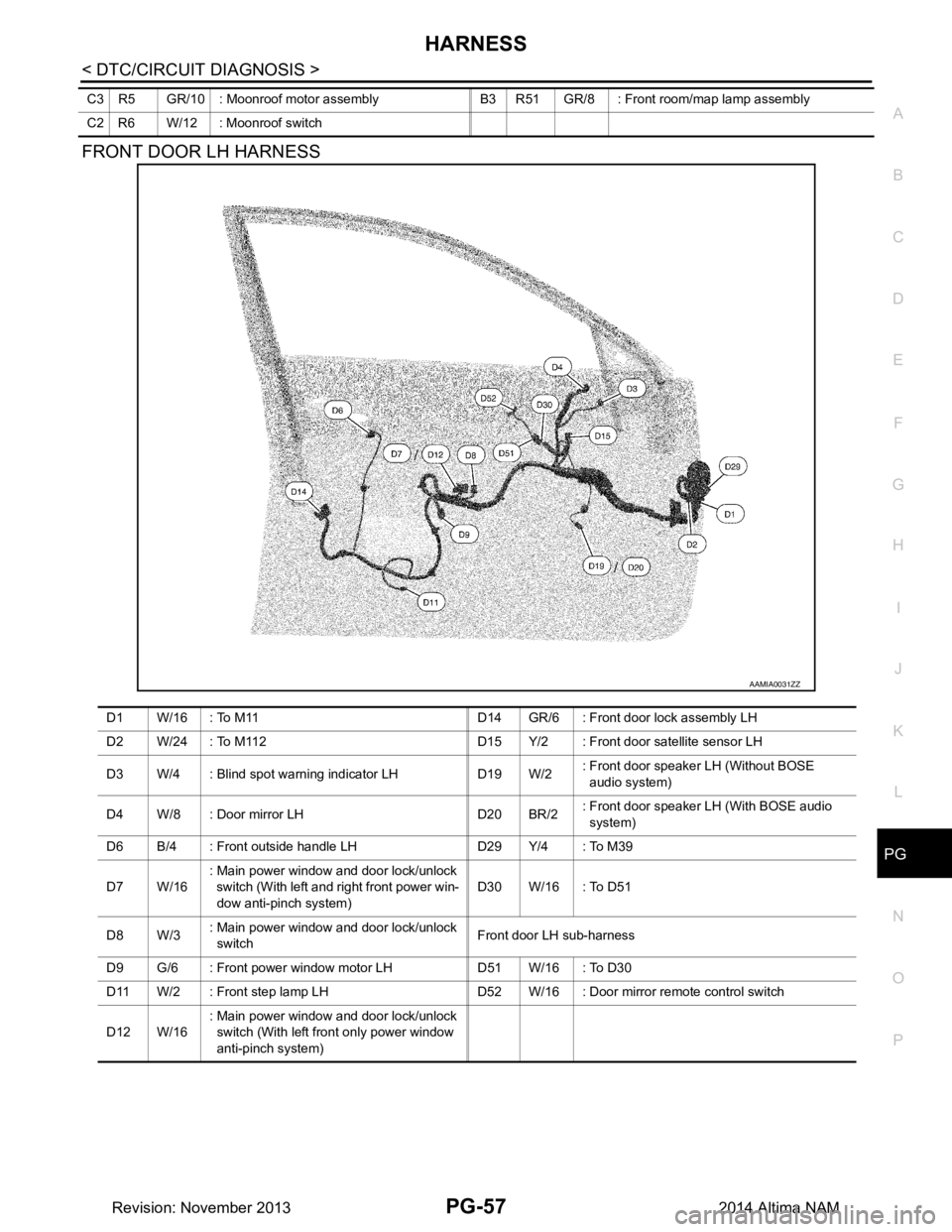
FRONT DOOR LH HARNESS
C3 R5 GR/10 : Moonroof motor assembly B3 R51 GR/8 : Front room/map lamp assembly
C2 R6 W/12 : Moonroof switch
AAMIA0031ZZ
D1 W/16 : To M11 D14 GR/6 : Front door lock assembly LH
D2 W/24 : To M112 D15 Y/2 : Front door satellite sensor LH
D3 W/4 : Blind spot warning indicator LH D19 W/2 : Front door speaker LH (Without BOSE
audio system)
D 4 W / 8 : D o o r m i r r o r L H D 2 0 B R / 2 : Front door speaker LH (With BOSE audio
system)
D6 B/4 : Front outside handle LH D29 Y/4 : To M39
D 7 W / 1 6 : Main power window and door lock/unlock
switch (With left and right front power win-
dow anti-pinch system) D 3 0 W / 1 6 : To D 5 1
D 8 W / 3 : Main power window and door lock/unlock
switch Front door LH sub-harness
D 9 G / 6 : F r o n t p o w e r w i n d o w m o t o r L H D 5 1 W / 1 6 : To D 3 0
D11 W/2 : Front step lamp LH D52 W/16 : Door mirror remote control switch
D 1 2 W / 1 6 : Main power window and door lock/unlock
switch (With left front only power window
anti-pinch system)
Revision: November 20132014 Altima NAM
Page 3508 of 4801
PWC-1
BODY EXTERIOR, DOORS, ROOF & VEHICLE SECURITY
C
D E
F
G H
I
J
L
M
SECTION PWC
A
B
PWC
N
O P
CONTENTS
POWER WINDOW CONTROL SYSTEM
LH FRONT ONLY ANTI-PINCH
PRECAUTION ................ ...............................
6
PRECAUTIONS .............................................. .....6
Precaution for Supplemental Restraint System
(SRS) "AIR BAG" and "SEAT BELT PRE-TEN-
SIONER" ............................................................. ......
6
Precaution for Work ..................................................6
PREPARATION ............................................7
PREPARATION .............................................. .....7
Special Service Tool ........................................... ......7
SYSTEM DESCRIPTION ..............................8
COMPONENT PARTS ................................... .....8
Component Parts Location ................................ ......8
Component Description .............................................8
SYSTEM .............................................................10
System Diagram ................................................. ....10
System Description .................................................10
Fail-safe ..................................................................11
DIAGNOSIS SYSTEM (BCM) ............................13
COMMON ITEM ..................................................... ....13
COMMON ITEM : CONSULT Function (BCM -
COMMON ITEM) ................................................. ....
13
RETAINED PWR ................................................... ....14
RETAINED PWR : CONSULT Function (BCM -
RETAINED PWR) ............................................... ....
14
ECU DIAGNOSIS INFORMATION ..............15
BCM (BODY CONTROL MODULE) ............... ....15
List of ECU Reference ........................................ ....15
POWER WINDOW MAIN SWITCH ....................16
Reference Value ................................................. ....16
WIRING DIAGRAM ......................................18
POWER WINDOW SYSTEM .............................18
Wiring Diagram - With Left Front Only Power Win-
dow Anti- Pinch .................................................... ....
18
BASIC INSPECTION ...................................25
DIAGNOSIS AND REPAIR WORKFLOW ........25
Work Flow ............................................................ ....25
INSPECTION AND ADJUSTMENT ..................27
ADDITIONAL SERVICE WHEN REMOVING BAT-
TERY NEGATIVE TERMINAL ............................... ....
27
ADDITIONAL SERVICE WHEN REMOVING
BATTERY NEGATIVE TERMINAL : Description . ....
27
ADDITIONAL SERVICE WHEN REMOVING
BATTERY NEGATIVE TERMINAL : Special Re-
pair Requirement ................................................. ....
27
ADDITIONAL SERVICE WHEN REPLACING
CONTROL UNIT .................................................... ....
27
ADDITIONAL SERVICE WHEN REPLACING
CONTROL UNIT : Description ............................. ....
27
ADDITIONAL SERVICE WHEN REPLACING
CONTROL UNIT : Special Repair Requirement .. ....
27
DTC/CIRCUIT DIAGNOSIS .........................29
POWER SUPPLY AND GROUND CIRCUIT ....29
BCM ....................................................................... ....29
BCM : Diagnosis Procedure ....................................29
POWER WINDOW MAIN SWITCH ........................ ....29
POWER WINDOW MAIN SWITCH : Description ....29
POWER WINDOW MAIN SWITCH : Component
Function Check .................................................... ....
30
POWER WINDOW MAIN SWITCH : Diagnosis
Procedure ............................................................ ....
30
POWER WINDOW MAIN SWITCH : Component
Inspection ............................................................ ....
33
Revision: November 20132014 Altima NAMRevision: November 20132014 Altima NAM
Page 3666 of 4801

RF-1
BODY EXTERIOR, DOORS, ROOF & VEHICLE SECURITY
C
D E
F
G H
I
J
L
M
SECTION RF
A
B
RF
N
O P
CONTENTS
ROOF
PRECAUTION ................ ...............................3
PRECAUTIONS .............................................. .....3
Precaution for Supplemental Restraint System
(SRS) "AIR BAG" and "SEAT BELT PRE-TEN-
SIONER" ............................................................. ......
3
Precaution for Work ..................................................3
PREPARATION ............................................4
PREPARATION .............................................. .....4
Special Service Tools ........................................ ......4
Commercial Service Tools .......................................4
SYSTEM DESCRIPTION ..............................5
COMPONENT PARTS ................................... .....5
MOONROOF .......................................................... ......5
MOONROOF : Component Parts Location .............5
MOONROOF : Component Description ...................5
SYSTEM ..............................................................6
MOONROOF .......................................................... ......6
MOONROOF : System Diagram ..............................6
MOONROOF : System Description ...........................6
DIAGNOSIS SYSTEM (BCM) .............................8
COMMON ITEM ..................................................... ......8
COMMON ITEM : CONSULT Function (BCM -
COMMON ITEM) ................................................. ......
8
RETAINED PWR ................................................... ......8
RETAINED PWR : CONSULT Function (BCM -
RETAINED PWR) ............................................... ......
9
ECU DIAGNOSIS INFORMATION ..............10
BCM (BODY CONTROL MODULE) ............... ....10
List of ECU Reference ........................................ ....10
MOONROOF MOTOR ASSEMBLY ...................11
Reference Value .................................................. ....11
WIRING DIAGRAM ......................................12
MOONROOF SYSTEM .....................................12
Wiring Diagram .................................................... ....12
BASIC INSPECTION ...................................18
DIAGNOSIS AND REPAIR WORKFLOW ........18
Work Flow ............................................................ ....18
INSPECTION AND ADJUSTMENT ..................20
ADDITIONAL SERVICE WHEN REPLACING
CONTROL UNIT .................................................... ....
20
ADDITIONAL SERVICE WHEN REPLACING
CONTROL UNIT : Description ............................. ....
20
ADDITIONAL SERVICE WHEN REPLACING
CONTROL UNIT : Special Repair Requirement .. ....
20
DTC/CIRCUIT DIAGNOSIS .........................21
POWER SUPPLY AND GROUND CIRCUIT ....21
BCM ....................................................................... ....21
BCM : Diagnosis Procedure ....................................21
MOONROOF MOTOR ASSEMBLY ...........................21
MOONROOF MOTOR ASSEM BLY : Description ....21
MOONROOF MO TOR ASSEMBLY :
Component Function Check .............................. ....
22
MOONROOF MOTOR ASSEMBLY :
Diagnosis Procedure .......................................... ....
22
MOONROOF MOTOR ASSEMBLY : Component
Inspection ............................................................ ....
24
MOONROOF MOTOR ASSEMBLY : Special Re-
pair Requirement ................................................. ....
25
MOONROOF SWITCH ......................................26
Description ...............................................................26
Diagnosis Procedure ..............................................26
Component Inspection .............................................27
Revision: November 20132014 Altima NAMRevision: November 20132014 Altima NAM
Page 3667 of 4801

RF-2
DOOR SWITCH .................................................28
Description ........................................................... ...28
Component Function Check .................................28
Diagnosis Procedure ..............................................28
Component Inspection ............................................29
SYMPTOM DIAGNOSIS .............................30
MOONROOF DOES NOT OPERATE PROP-
ERLY ............................................................... ...
30
Diagnosis Procedure ........................................... ...30
AUTO OPERATION DOES NOT OPERATE .....31
Diagnosis Procedure ........................................... ...31
MOONROOF DOES NOT OPERATE ANTI-
PINCH FUNCTIO N .......................................... ...
32
Diagnosis Procedure ........................................... ...32
DOES NOT STOP FULLY-OPEN OR FULLY-
CLOSED POSITION ....................................... ...
33
Diagnosis Procedure ........................................... ...33
RETAINED POWER OPERATION DOES NOT
OPERATE PROPERLY .................................. ...
34
Diagnosis Procedure ........................................... ...34
SQUEAK AND RATTLE TROUBLE DIAG-
NOSES ......................... ......................................
35
Work Flow ............................................................ ...35
Generic Squeak and Rattle Troubleshooting ....... ...37
Diagnostic Worksheet .............................................39
REMOVAL AND INSTALLATION ..............41
GLASS LID ..................................................... ...41
Removal and Installation .........................................41
MOONROOF MOTOR ASSEMBLY ............... ...42
Removal and Installation .........................................42
MOONROOF UNIT ASSEMBLY .................... ...43
Inspection ............................................................. ...43
Exploded View ........................................................46
Removal and Installation .........................................46
SUNSHADE .................................................... ...48
Removal and Installation .........................................48
WIND DEFLECTOR ........................................ ...49
Removal and Installation .........................................49
MOONROOF SWITCH ................................... ...50
Removal and Installation .........................................50
UNIT DISASSEMBLY AND ASSEMBLY ...51
MOONROOF UNIT ASSEMBLY .................... ...51
Exploded View ..................................................... ...51
Disassembly and Assembly ....................................51
Revision: November 20132014 Altima NAMRevision: November 20132014 Altima NAM
Page 3670 of 4801
COMPONENT PARTSRF-5
< SYSTEM DESCRIPTION >
C
D E
F
G H
I
J
L
M A
B
RF
N
O P
SYSTEM DESCRIPTION
COMPONENT PARTS
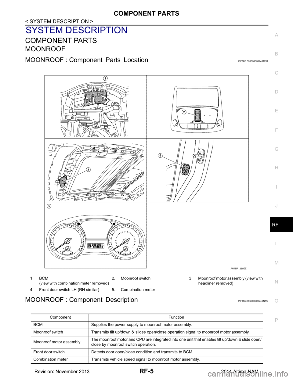
MOONROOF
MOONROOF : Component Parts LocationINFOID:0000000009461291
MOONROOF : Component DescriptionINFOID:0000000009461292
AWBIA1289ZZ
1. BCM (view with combinat ion meter removed) 2. Moonroof switch 3. Moonroof motor assembly (view with
headliner removed)
4. Front door switch LH (RH similar) 5. Combination meter
Component Function
BCM Supplies the power supply to moonroof motor assembly.
Moonroof switch Transmits tilt up/down & slides open/close operation signal to moonroof motor assembly.
Moonroof mo tor assembly The moonroof motor and CPU are integrated into one unit that enables tilt up/down & slide open/
close by moonroof switch operation.
Front door switch Detects door open/close condition and transmits to BCM.
Combination meter Transmits vehicle speed signal to moonroof motor assembly.
Revision: November 20132014 Altima NAMRevision: November 20132014 Altima NAM
Page 3671 of 4801
RF-6
< SYSTEM DESCRIPTION >
SYSTEM
SYSTEM
MOONROOF
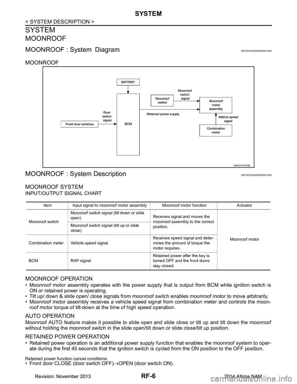
MOONROOF : System DiagramINFOID:0000000009461293
MOONROOF
MOONROOF : System DescriptionINFOID:0000000009461294
MOONROOF SYSTEM
INPUT/OUTPUT SIGNAL CHART
MOONROOF OPERATION
• Moonroof motor assembly operates with the power supply that is output from BCM while ignition switch isON or retained power is operating.
• Tilt up/ down & slide open/ close signals from moonroof switch enables moonroof motor to move arbitrarily.
• Moonroof motor assembly receives a vehicle speed signal from combination meter and controls the moon- roof motor torque of tilt-down at the time of high speed operation.
AUTO OPERATION
Moonroof AUTO feature makes it possible to slide open and slide close or tilt up and tilt down the moonroof
without holding the moonroof switch in the slide open/tilt down or slide close/tilt up position.
RETAINED POWER OPERATION
• Retained power operation is an additional power supply function that enables the moonroof system to oper-
ate during the first 45 seconds that the ignition switch is cycled from the ON position to the OFF position.
Retained power function cancel conditions• Front door CLOSE (door switch OFF)→OPEN (door switch ON).
AWKIA1975GB
Item Input signal to moonroof motor assembly Moonroof motor function Actuator
Moonroof switch Moonroof switch signal (tilt down or slide
open) Receives signal and moves the
moonroof assembly to the correct
position.
Moonroof motor
Moonroof switch signal (tilt up or slide
close)
Combination meter Vehicle speed signal Receives speed signal and deter-
mines the amount of torque the
motor requires.
BCM RAP signal Retained power after the key is
turned OFF and the front doors
stay closed.
Revision: November 20132014 Altima NAMRevision: November 20132014 Altima NAM