2014 NISSAN TEANA lock
[x] Cancel search: lockPage 2503 of 4801
FSU-2
< PRECAUTION >
PRECAUTIONS
PRECAUTION
PRECAUTIONS
Precaution for Supplemental Restraint System (SRS) "AIR BAG" and "SEAT BELT
PRE-TENSIONER"
INFOID:0000000009951705
The Supplemental Restraint System such as “A IR BAG” and “SEAT BELT PRE-TENSIONER”, used along
with a front seat belt, helps to reduce the risk or severi ty of injury to the driver and front passenger for certain
types of collision. Information necessary to service the system safely is included in the SR and SB section of
this Service Manual.
WARNING:
• To avoid rendering the SRS inopera tive, which could increase the risk of personal injury or death in
the event of a collision which would result in air bag inflation, all maintenance must be performed by
an authorized NISS AN/INFINITI dealer.
• Improper maintenance, including in correct removal and installation of the SRS, can lead to personal
injury caused by unintent ional activation of the system. For re moval of Spiral Cable and Air Bag
Module, see the SR section.
• Do not use electrical test equipmen t on any circuit related to the SRS unless instructed to in this
Service Manual. SRS wiring harn esses can be identified by yellow and/or orange harnesses or har-
ness connectors.
PRECAUTIONS WHEN USING POWER TOOLS (AIR OR ELECTRIC) AND HAMMERS
WARNING:
• When working near the Airbag Diagnosis Sensor Unit or other Airbag System sensors with the Igni-
tion ON or engine running, DO NOT use air or electri c power tools or strike near the sensor(s) with a
hammer. Heavy vibration could activate the sensor( s) and deploy the air bag(s), possibly causing
serious injury.
• When using air or electric power tools or hammers , always switch the Ignition OFF, disconnect the
battery and wait at least three minutes before performing any service.
General PrecautionsINFOID:0000000009460620
• When installing rubber bushings, the final tightening mu st be carried out under unladen conditions with tires
on ground. Oil might shorten the life of rubber bushings. Be sure to wipe off any spilled oil.
- Unladen conditions mean that fuel, engine coolant and lubricant are full. Spare tire, jack, hand tools and mats are in designated positions.
• After servicing suspension parts, be sure to check wheel alignment.
• Self-lock nuts are not reusable. Always use new ones when installing. Since new self-lock nuts are pre-oiled,
tighten as they are.
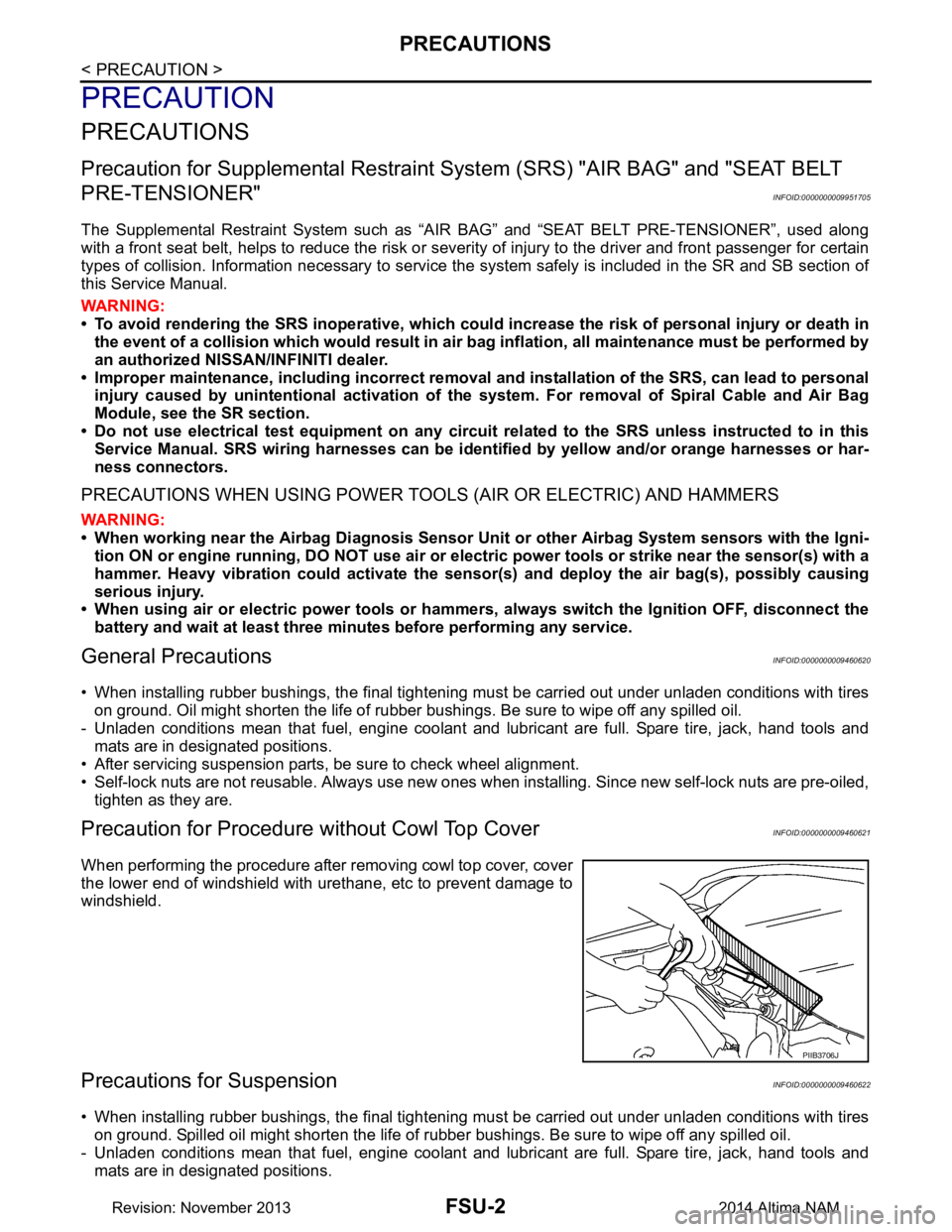
Precaution for Procedure without Cowl Top CoverINFOID:0000000009460621
When performing the procedure after removing cowl top cover, cover
the lower end of windshield with urethane, etc to prevent damage to
windshield.
Precautions for SuspensionINFOID:0000000009460622
• When installing rubber bushings, the final tightening mu st be carried out under unladen conditions with tires
on ground. Spilled oil might shorten the life of rubber bushings. Be sure to wipe off any spilled oil.
- Unladen conditions mean that fuel, engine coolant and lubricant are full. Spare tire, jack, hand tools and mats are in designated positions.
PIIB3706J
Revision: November 20132014 Altima NAM
Page 2504 of 4801

PRECAUTIONSFSU-3
< PRECAUTION >
C
D
F
G H
I
J
K L
M A
B
FSU
N
O P
• After servicing suspension parts, be sure to check wheel alignment.
• Self-lock nuts are not reusable. Always use new ones when installing. Since new self-lock nuts are pre-oiled, tighten as they are.
Revision: November 20132014 Altima NAM
Page 2510 of 4801
FRONT COIL SPRING AND STRUTFSU-9
< REMOVAL AND INSTALLATION >
C
D
F
G H
I
J
K L
M A
B
FSU
N
O P
REMOVAL AND INSTALLATION
FRONT COIL SPRING AND STRUT
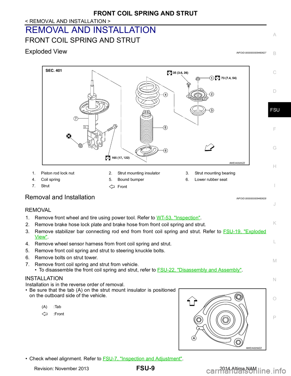
Exploded ViewINFOID:0000000009460627
Removal and InstallationINFOID:0000000009460628
REMOVAL
1. Remove front wheel and tire using power tool. Refer to WT-53, "Inspection".
2. Remove brake hose lock plate and brake hose from front coil spring and strut.
3. Remove stabilizer bar connecting rod end from front coil spring and strut. Refer to FSU-19, "Exploded
View".
4. Remove wheel sensor harness from front coil spring and strut.
5. Remove front coil spring and strut to steering knuckle bolts.
6. Remove bolts on strut tower.
7. Remove front coil spring and strut from vehicle. • To disassemble the front coil spring and strut, refer to FSU-22, "Disassembly and Assembly"
.
INSTALLATION
Installation is in the reverse order of removal.
• Be sure that the tab (A) on the strut mount insulator is positioned on the outboard side of the vehicle.
• Check wheel alignment. Refer to FSU-7, "Inspection and Adjustment"
.
1. Piston rod lock nut 2. Strut mounting insulator 3. Strut mounting bearing
4. Coil spring 5. Bound bumper 6. Lower rubber seat
7. Strut Front
AWEIA0325ZZ
(A) :Tab
:Front
AWEIA0259ZZ
Revision: November 20132014 Altima NAM
Page 2519 of 4801
FSU-18
< REMOVAL AND INSTALLATION >
STEERING KNUCKLE
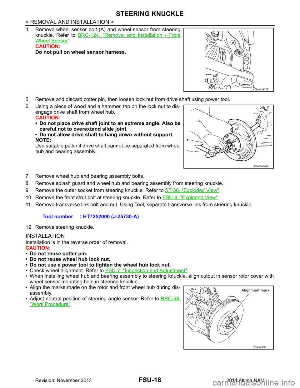
4. Remove wheel sensor bolt (A) and wheel sensor from steeringknuckle. Refer to BRC-124, "Removal and Installation - Front
Wheel Sensor".
CAUTION:
Do not pull on wheel sensor harness.
5. Remove and discard cotter pin, then loosen lock nut from drive shaft using power tool.
6. Using a piece of wood and a hammer, tap on the lock nut to dis- engage drive shaft from wheel hub.
CAUTION:
• Do not place drive shaft joint to an extreme angle. Also be
careful not to over extend slide joint.
• Do not allow drive shaft to hang down without support.
NOTE:
Use suitable puller if drive shaft cannot be separated from wheel
hub and bearing assembly.
7. Remove wheel hub and bearing assembly bolts.
8. Remove splash guard and wheel hub and bearing assembly from steering knuckle.
9. Remove the outer socket from steering knuckle. Refer to ST-36, "Exploded View"
.
10. Remove the front strut bolt at steering knuckle. Refer to FSU-9, "Exploded View"
.
11. Remove transverse link bolt and nut. Using Tool, separate transverse link from steering knuckle.
12. Remove steering knuckle.
INSTALLATION
Installation is in the reverse order of removal.
CAUTION:
• Do not reuse cotter pin.
• Do not reuse wheel hub lock nut.
• Do not use a power tool to tighten the wheel hub lock nut.
• Check wheel alignment. Refer to FSU-7, "Inspection and Adjustment"
.
• When installing wheel hub and bearing assembly to steering knuckle, align cutout in sensor rotor cover with
wheel sensor mounting hole in steering knuckle.
• Align the marks made on the rotor and front wheel hub during dis- assembly.
• Adjust neutral position of steering angle sensor. Refer to BRC-58,
"Work Procedure".
ALDIA0287ZZ
JPDIG0070ZZ
Tool number : HT7252000 (J-25730-A)
SDIA1480E
Revision: November 20132014 Altima NAM
Page 2523 of 4801
FSU-22
< UNIT DISASSEMBLY AND ASSEMBLY >
FRONT COIL SPRING AND STRUT
UNIT DISASSEMBLY AND ASSEMBLY
FRONT COIL SPRING AND STRUT
Disassembly and AssemblyINFOID:0000000009460638
DISASSEMBLY
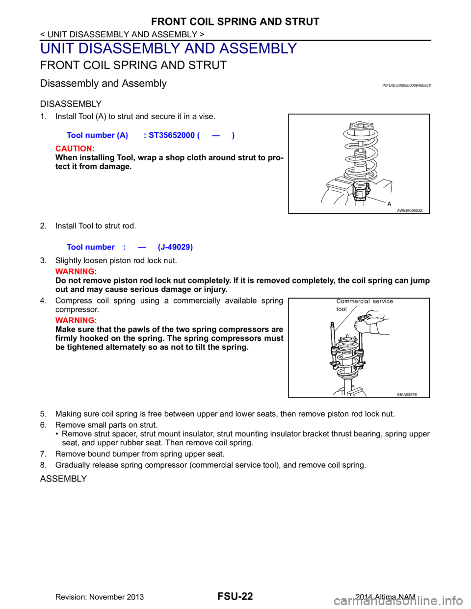
1. Install Tool (A) to strut and secure it in a vise.CAUTION:
When installing Tool, wrap a sh op cloth around strut to pro-
tect it from damage.
2. Install Tool to strut rod.
3. Slightly loosen piston rod lock nut. WARNING:
Do not remove piston rod lock nut completely. If it is removed completely, the coil spring can jump
out and may cause serious damage or injury.
4. Compress coil spring using a commercially available spring compressor.
WARNING:
Make sure that the pawls of the two spring compressors are
firmly hooked on the spring. The spring compressors must
be tightened alternately so as not to tilt the spring.
5. Making sure coil spring is free between upper and lower seats, then remove piston rod lock nut.
6. Remove small parts on strut. • Remove strut spacer, strut mount insulator, strut mounting insulator bracket thrust bearing, spring upper
seat, and upper rubber seat. Then remove coil spring.
7. Remove bound bumper from spring upper seat.
8. Gradually release spring compressor (commercial service tool), and remove coil spring.
ASSEMBLY
Tool number (A) : ST35652000 ( — )
AWEIA0262ZZ
Tool number : — (J-49029)
SEIA0297E
Revision: November 20132014 Altima NAM
Page 2524 of 4801
FRONT COIL SPRING AND STRUTFSU-23
< UNIT DISASSEMBLY AND ASSEMBLY >
C
D
F
G H
I
J
K L
M A
B
FSU
N
O P
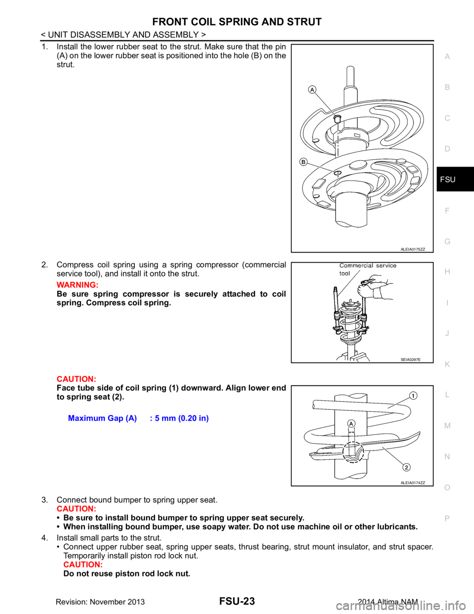
1. Install the lower rubber seat to the strut. Make sure that the pin (A) on the lower rubber seat is positioned into the hole (B) on the
strut.
2. Compress coil spring using a spring compressor (commercial service tool), and install it onto the strut.
WARNING:
Be sure spring compressor is securely attached to coil
spring. Compress coil spring.
CAUTION:
Face tube side of coil spring (1) downward. Align lower end
to spring seat (2).
3. Connect bound bumper to spring upper seat. CAUTION:
• Be sure to install bound bump er to spring upper seat securely.
• When installing bound bumper, use soapy water. Do not use machine oil or other lubricants.
4. Install small parts to the strut. • Connect upper rubber seat, spring upper seats, thrust bearing, strut mount insulator, and strut spacer.
Temporarily install piston rod lock nut.
CAUTION:
Do not reuse piston rod lock nut.
ALEIA0175ZZ
SEIA0297E
Maximum Gap (A) : 5 mm (0.20 in)
ALEIA0174ZZ
Revision: November 20132014 Altima NAM
Page 2525 of 4801
FSU-24
< UNIT DISASSEMBLY AND ASSEMBLY >
FRONT COIL SPRING AND STRUT
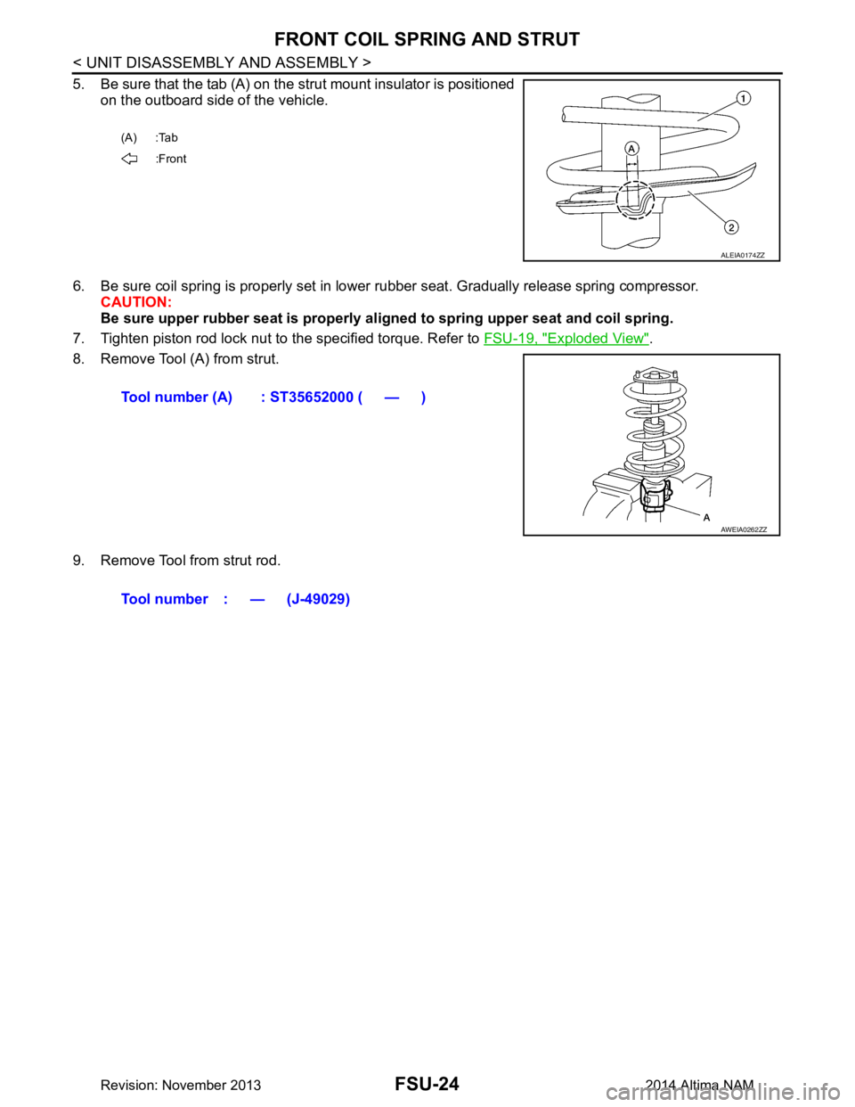
5. Be sure that the tab (A) on the strut mount insulator is positionedon the outboard side of the vehicle.
6. Be sure coil spring is properly set in lower rubber seat. Gradually release spring compressor. CAUTION:
Be sure upper rubber seat is properly al igned to spring upper seat and coil spring.
7. Tighten piston rod lock nut to the specified torque. Refer to FSU-19, "Exploded View"
.
8. Remove Tool (A) from strut.
9. Remove Tool from strut rod.
(A) :Tab :Front
ALEIA0174ZZ
Tool number (A) : ST35652000 ( — )
AWEIA0262ZZ
Tool number : — (J-49029)
Revision: November 20132014 Altima NAM
Page 2531 of 4801
HOW TO USE THIS MANUALGI-3
< HOW TO USE THIS MANUAL >
C
D E
F
G H
I
J
K L
M B
GI
N
O PHOW TO USE THIS MANUAL
HOW TO USE THIS MANUAL
DescriptionINFOID:0000000009462967
This volume explains “Removal, Disassembly, Inst allation, Inspection and Adjustment” and “Trouble Diag-
noses”.
Te r m sINFOID:0000000009462968
• The captions WARNING and CAUTION warn you of steps that must be followed to prevent personal injury
and/or damage to some part of the vehicle.
WARNING indicates the possibility of personal injury if instructions are not followed.
CAUTION indicates the possibility of component damage if instructions are not followed.
BOLD TYPED STATEMENTS except WARNING and CAUTION give you helpful information.
Standard value: Tolerance at inspection and adjustment.
Limit value: The maximum or minimum limit val ue that should not be exceeded at inspection and adjust-
ment.
UnitsINFOID:0000000009462969
• The UNITS given in this manual are primarily expressed as the SI UNIT (International System of Unit), and
alternatively expressed in the metric system and in the yard/pound system.
Also with regard to tightening torque of bolts and nuts, there are descriptions both about range and about the
standard tightening torque.
“Example”
Range
Standard
ContentsINFOID:0000000009462970
• A QUICK REFERENCE INDEX , a black tab (e.g. ) is provided on the first page. You can quickly find the
first page of each section by matching it to the section's black tab.
• THE CONTENTS are listed on the first page of each section.
• THE TITLE is indicated on the upper portion of each page and shows the part or system.
• THE PAGE NUMBER of each section consists of two or three letters which designate the particular section
and a number (e.g. “BR-5”).
• THE SMALL ILLUSTRATIONS show the important steps such as ins pection, use of special tools, knacks of
work and hidden or tricky steps which are not s hown in the previous large illustrations.
Assembly, inspection and adjustment procedures for the complicated units such as the automatic transaxle
or transmission, etc. are presented in a step-by-step format where necessary.
Outer Socket Lock Nut : 59 - 78 N·m (6.0 - 8.0 kg-m, 43 - 58 ft-lb)
Drive Shaft Installation Bolt : 44.3 N·m (4.5 kg-m, 33 ft-lb)
Revision: November 20132014 Altima NAMRevision: November 20132014 Altima NAM