2014 NISSAN TEANA lock
[x] Cancel search: lockPage 2426 of 4801
EXT-12
< PERIODIC MAINTENANCE >
SQUEAK AND RATTLE TROUBLE DIAGNOSES
INSTRUMENT PANEL
Most incidents are caused by contact and movement between:
1. Cluster lid A and the instrument panel
2. Acrylic lens and combination meter housing
3. Instrument panel to front pillar finisher
4. Instrument panel to windshield
5. Instrument panel pins
6. Wiring harnesses behind the combination meter
7. A/C defroster duct and duct joint
These incidents can usually be located by tapping or moving the components to duplicate the noise or by
pressing on the components while driving to stop the noise. Most of these incidents can be repaired by apply-
ing felt cloth tape or silicone spray (in hard to reach areas). Urethane pads can be used to insulate wiring har-
ness.
CAUTION:
Do not use silicone spray to isolate a squeak or ra ttle. If you saturate the area with silicone, you will
not be able to recheck the repair.
CENTER CONSOLE
Components to pay attention to include:
1. Shift selector assembly cover to finisher
2. A/C control unit and cluster lid C
3. Wiring harnesses behind audio and A/C control unit
The instrument panel repair and isolation pr ocedures also apply to the center console.
DOORS
Pay attention to the:
1. Finisher and inner panel making a slapping noise
2. Inside handle escutcheon to door finisher
3. Wiring harnesses tapping
4. Door striker out of alignment causing a popping noise on starts and stops
Tapping or moving the components or pressing on them wh ile driving to duplicate the conditions can isolate
many of these incidents. You can usually insulate the areas with felt cloth tape or insulator foam blocks from
the NISSAN Squeak and Rattle Kit (J-50397) to repair the noise.
TRUNK
Trunk noises are often caused by a loose jack or loose items put into the trunk by the owner.
In addition look for:
1. Trunk lid bumpers out of adjustment
2. Trunk lid striker out of adjustment
3. The trunk lid torsion bars knocking together
4. A loose license plate or bracket
Most of these incidents can be repaired by adjusting, se curing or insulating the item(s) or component(s) caus-
ing the noise.
SUNROOF/HEADLINING
Noises in the sunroof/headlining area c an often be traced to one of the following:
1. Sunroof lid, rail, linkage or seals making a rattle or light knocking noise
2. Sun visor shaft shaking in the holder
3. Front or rear windshield touching headlining and squeaking
Again, pressing on the components to stop the noise while duplicating the conditions can isolate most of these
incidents. Repairs usually consist of insulating with felt cloth tape.
OVERHEAD CONSOLE (FRONT AND REAR)
Overhead console noises are often caused by the c onsole panel clips not being engaged correctly. Most of
these incidents are repaired by pushing up on the c onsole at the clip locations until the clips engage.
In addition look for:
Revision: November 20132014 Altima NAM
Page 2427 of 4801
SQUEAK AND RATTLE TROUBLE DIAGNOSESEXT-13
< PERIODIC MAINTENANCE >
C
D E
F
G H
I
J
L
M A
B
EXT
N
O P
1. Loose harness or harness connectors.
2. Front console map/reading lamp lens loose.
3. Loose screws at console attachment points.
SEATS
When isolating seat noise it's important to note the pos ition the seat is in and the load placed on the seat when
the noise is present. These conditions should be duplic ated when verifying and isolating the cause of the
noise.
Cause of seat noise include:
1. Headrest rods and holder
2. A squeak between the seat pad cushion and frame
3. The rear seatback lock and bracket
These noises can be isolated by moving or pressing on the suspected components while duplicating the con-
ditions under which the noise occurs. Most of thes e incidents can be repaired by repositioning the component
or applying urethane tape to the contact area.
UNDERHOOD
Some interior noise may be caused by components under the hood or on the engine wall. The noise is then
transmitted into the passenger compartment.
Causes of transmitted underhood noise include:
1. Any component installed to the engine wall
2. Components that pass through the engine wall
3. Engine wall mounts and connectors
4. Loose radiator installation pins
5. Hood bumpers out of adjustment
6. Hood striker out of adjustment
These noises can be difficult to isolate since they cannot be reached from the interior of the vehicle. The best
method is to secure, move or insulate one component at a time and test drive the vehicle. Also, engine rpm or
load can be changed to isolate the noise. Repairs can usually be made by moving, adjusting, securing, or
insulating the component causing the noise.
Revision: November 20132014 Altima NAM
Page 2431 of 4801
FRONT BUMPEREXT-17
< REMOVAL AND INSTALLATION >
C
D E
F
G H
I
J
L
M A
B
EXT
N
O P
Removal and InstallationINFOID:0000000009460995
REMOVAL
1. Remove the core support cover clips (A), then remove the core support cover (1).
2. Partially remove the front fender protectors (LH/RH). Refer to EXT-26, "FENDER PROTECTOR :
Removal and Installation".
3. Remove the front under cover. Refer to EXT-28, "Removal and Installation"
.
4. Remove the hood ledge finisher.
5. Remove the front bumper fascia to upper fender screws (A) (LH/ RH), then rotate clockwise each front bumper fascia upper side
bracket (1) to remove.
1. Core support cover 2. Front bumper fascia hood seal 3. Front bumper fascia upper retainer
bracket
4. Front bumper fascia upper retainer bracket (RH) 5. Front bumper reinforcement bracket 6. Front bumper fascia upper retainer
bracket (LH)
7. Front bumper fascia upper retainer upper center bracket 8. Front bumper fascia side bracket
(RH) 9. Front bumper reinforcement support
(RH)
10. Front bumper reinforcement 11. Front energy absorber 12. Front bumper fascia upper side bracket (RH)
13. Front bumper fascia side stiffener (RH) 14. Front fog lamp (RH) (if equipped) 15. Front fog lamp finisher (RH) (if
equipped)
16. Turn signal and hazard warning lamp (RH) 17. Front bumper fascia finisher (RH) (if
equipped) 18. Tow cover
19. Front license plate bracket (if equipped) 20. Turn signal and hazard warning
lamp (LH) 21. Front bumper fascia finisher (LH) (if
equipped)
22. Front fog lamp finisher (LH) (if equipped) 23. Front bumper fascia 24. Front fog lamp (LH) (if equipped)
25. Front bumper fascia side stiffener (LH) 26. Front bumper fascia upper side
bracket (LH) 27. Front bumper reinforcement support
(LH)
28. Front bumper fascia side bracket (LH) A. Clip
ALKIA2602ZZ
ALKIA2603ZZ
Revision: November 20132014 Altima NAM
Page 2461 of 4801
FRONT WHEEL HUBFAX-9
< REMOVAL AND INSTALLATION >
CEF
G H
I
J
K L
M A
B
FA X
N
O P
4. Remove wheel sensor bolt (A) and wheel sensor from steering knuckle. Refer to BRC-124, "Exploded View - Front Wheel Sen-
sor".
CAUTION:
Do not pull on wheel sensor harness.
5. Remove and discard cotter pin.
6. Remove nut retainer.
7. Loosen lock nut from drive shaft using power tool.
8. Using a piece of wood and a hammer, tap on the lock nut to dis- engage drive shaft from wheel hub.
CAUTION:
• Do not place drive shaft joint to an extreme angle. Also be careful not to over extend slide joint.
• Do not allow drive shaft to hang down without support.
NOTE:
Use suitable puller if drive shaft cannot be separated from wheel
hub and bearing assembly.
9. Remove wheel hub and bearing assembly bolts using power tool.
10. Remove splash guard and wheel hub and bearing assembly from steering knuckle.
INSTALLATION
Installation is in the reverse order of removal.
CAUTION:
• Do not use a power tool to tighten the wheel hub lock nut.
• Do not reuse the cotter pin or the wheel hub lock nut.
• Do not apply lubricating oil to the mating surface.
• When installing wheel hub and bearing assembly to steering knuckle, align cutout in sensor rotor cover with wheel sensor mounting hole in steering knuckle.
• Align the marks made on the rotor and front wheel hub during dis- assembly.
ALDIA0287ZZ
JPDIG0070ZZ
SDIA1480E
Revision: November 20132014 Altima NAM
Page 2462 of 4801
FAX-10
< REMOVAL AND INSTALLATION >
FRONT DRIVE SHAFT
FRONT DRIVE SHAFT
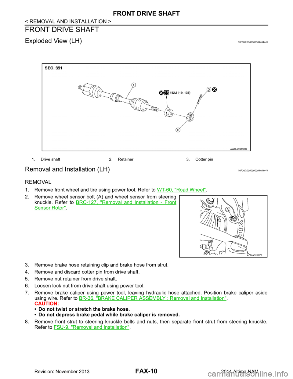
Exploded View (LH)INFOID:0000000009464440
Removal and Installation (LH)INFOID:0000000009464441
REMOVAL
1. Remove front wheel and tire using power tool. Refer to WT-60, "Road Wheel".
2. Remove wheel sensor bolt (A) and wheel sensor from steering knuckle. Refer to BRC-127, "Removal and Installation - Front
Sensor Rotor".
3. Remove brake hose retaining clip and brake hose from strut.
4. Remove and discard cotter pin from drive shaft.
5. Remove nut retainer from drive shaft.
6. Loosen lock nut from drive shaft using power tool.
7. Remove brake caliper using power tool, leaving hy draulic hose attached. Position brake caliper aside
using wire. Refer to BR-36, "BRAKE CALIPER ASSEMBLY : Removal and Installation"
.
CAUTION:
• Do not twist or stretch the brake hose.
• Do not depress brake pedal while brake caliper is removed.
8. Remove front strut to steering knuckle bolts and nut s, then separate front strut from steering knuckle.
Refer to FSU-9, "Removal and Installation"
.
1. Drive shaft 2. Retainer 3. Cotter pin
AWDIA0983GB
ALDIA0287ZZ
Revision: November 20132014 Altima NAM
Page 2463 of 4801
FRONT DRIVE SHAFTFAX-11
< REMOVAL AND INSTALLATION >
CEF
G H
I
J
K L
M A
B
FA X
N
O P
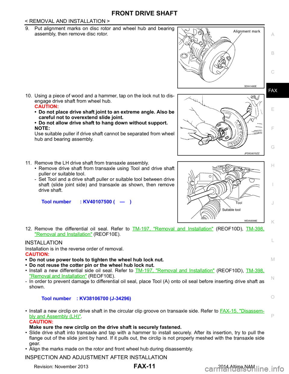
9. Put alignment marks on disc rotor and wheel hub and bearing assembly, then remove disc rotor.
10. Using a piece of wood and a hammer, tap on the lock nut to dis- engage drive shaft from wheel hub.
CAUTION:
• Do not place drive shaft joint to an extreme angle. Also be careful not to over extend slide joint.
• Do not allow drive shaft to hang down without support.
NOTE:
Use suitable puller if drive shaft cannot be separated from wheel
hub and bearing assembly.
11. Remove the LH drive shaf t from transaxle assembly.
• Remove drive shaft from transaxle using Tool and drive shaft puller or suitable tool.
- Set Tool and a drive shaft puller or suitable tool between drive
shaft (slide joint side) and transaxle as shown, then remove
drive shaft.
12. Remove the differential oil seal. Refer to TM-197, "Removal and Installation"
(REOF10D), TM-398,
"Removal and Installation" (REOF10E).
INSTALLATION
Installation is in the reverse order of removal.
CAUTION:
• Do not use power tools to ti ghten the wheel hub lock nut.
• Do not reuse the cotter pin or the wheel hub lock nut.
• Install a new differential side oil seal. Refer to TM-197, "Removal and Installation"
(REOF10D), TM-398,
"Removal and Installation" (REOF10E).
- In order to prevent damage to differential oil seal, plac e Tool (A) onto oil seal before inserting drive shaft as
shown.
• Install a new circlip on drive shaft in the circular clip groove on transaxle side. Refer to FAX-15, "Disassem-
bly and Assembly (LH)".
CAUTION:
Make sure the new circlip on the drive shaft is securely fastened.
• Slide drive shaft into transaxle and tap with a hammer to install securely. After its insertion, try to pull the
flange out of the slide joint by hand. If it pulls out, t he circlip is not properly meshed with the transaxle side
gear.
• Align the marks made on the rotor and front wheel hub during disassembly.
INSPECTION AND ADJUSTMENT AFTER INSTALLATION
SDIA1480E
JPDIG0070ZZ
Tool number : KV40107500 ( — )
WDIA0098E
Tool number : KV38106700 (J-34296)
Revision: November 20132014 Altima NAM
Page 2465 of 4801
FRONT DRIVE SHAFTFAX-13
< REMOVAL AND INSTALLATION >
CEF
G H
I
J
K L
M A
B
FA X
N
O P
3. Remove brake hose retaining clip and brake hose from strut.
4. Remove and discard cotter pin from drive shaft.
5. Remove nut retainer from drive shaft.
6. Loosen lock nut from drive shaft using power tool.
7. Remove brake caliper using power tool, leaving hy draulic brake hose attached. Position caliper aside
using wire. Refer to BR-36, "BRAKE CALIPER ASSEMBLY : Removal and Installation"
.
CAUTION:
• Do not twist or stretch the brake hose.
• Do not depress brake pedal while brake caliper is removed.
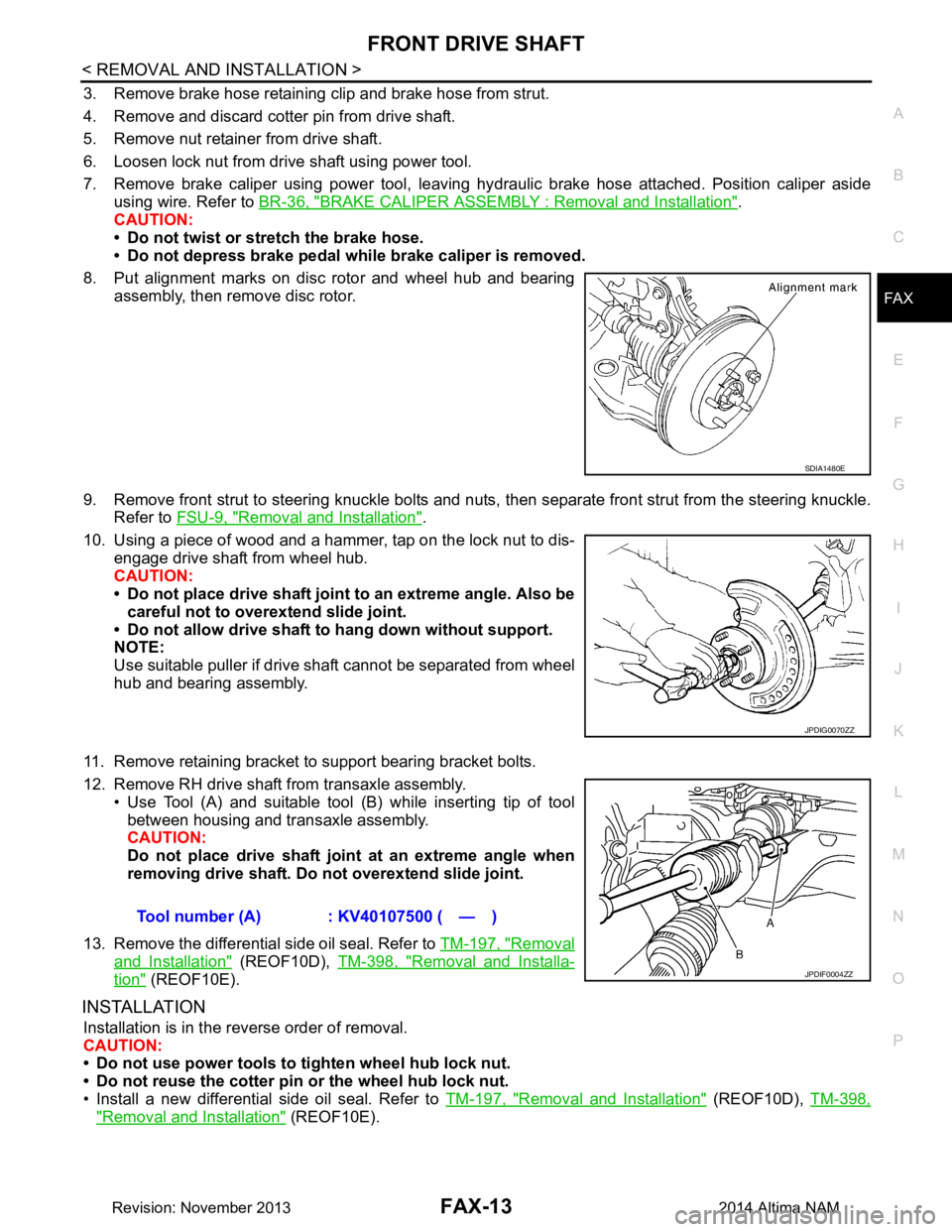
8. Put alignment marks on disc rotor and wheel hub and bearing assembly, then remove disc rotor.
9. Remove front strut to steering knuckle bolts and nuts, then separate front strut from the steering knuckle.
Refer to FSU-9, "Removal and Installation"
.
10. Using a piece of wood and a hammer, tap on the lock nut to dis- engage drive shaft from wheel hub.
CAUTION:
• Do not place drive shaft joint to an extreme angle. Also be careful not to over extend slide joint.
• Do not allow drive shaft to hang down without support.
NOTE:
Use suitable puller if drive shaft cannot be separated from wheel
hub and bearing assembly.
11. Remove retaining bracket to support bearing bracket bolts.
12. Remove RH drive shaft from transaxle assembly. • Use Tool (A) and suitable tool (B) while inserting tip of tool
between housing and transaxle assembly.
CAUTION:
Do not place drive shaft join t at an extreme angle when
removing drive shaft. Do not overextend slide joint.
13. Remove the differential side oil seal. Refer to TM-197, "Removal
and Installation" (REOF10D), TM-398, "Removal and Installa-
tion" (REOF10E).
INSTALLATION
Installation is in the reverse order of removal.
CAUTION:
• Do not use power tools to tighten wheel hub lock nut.
• Do not reuse the cotter pin or the wheel hub lock nut.
• Install a new differential side oil seal. Refer to TM-197, "Removal and Installation"
(REOF10D), TM-398,
"Removal and Installation" (REOF10E).
SDIA1480E
JPDIG0070ZZ
Tool number (A) : KV40107500 ( — )
JPDIF0004ZZ
Revision: November 20132014 Altima NAM
Page 2484 of 4801
FL-4
< PREPARATION >
PREPARATION
PREPARATION
PREPARATION
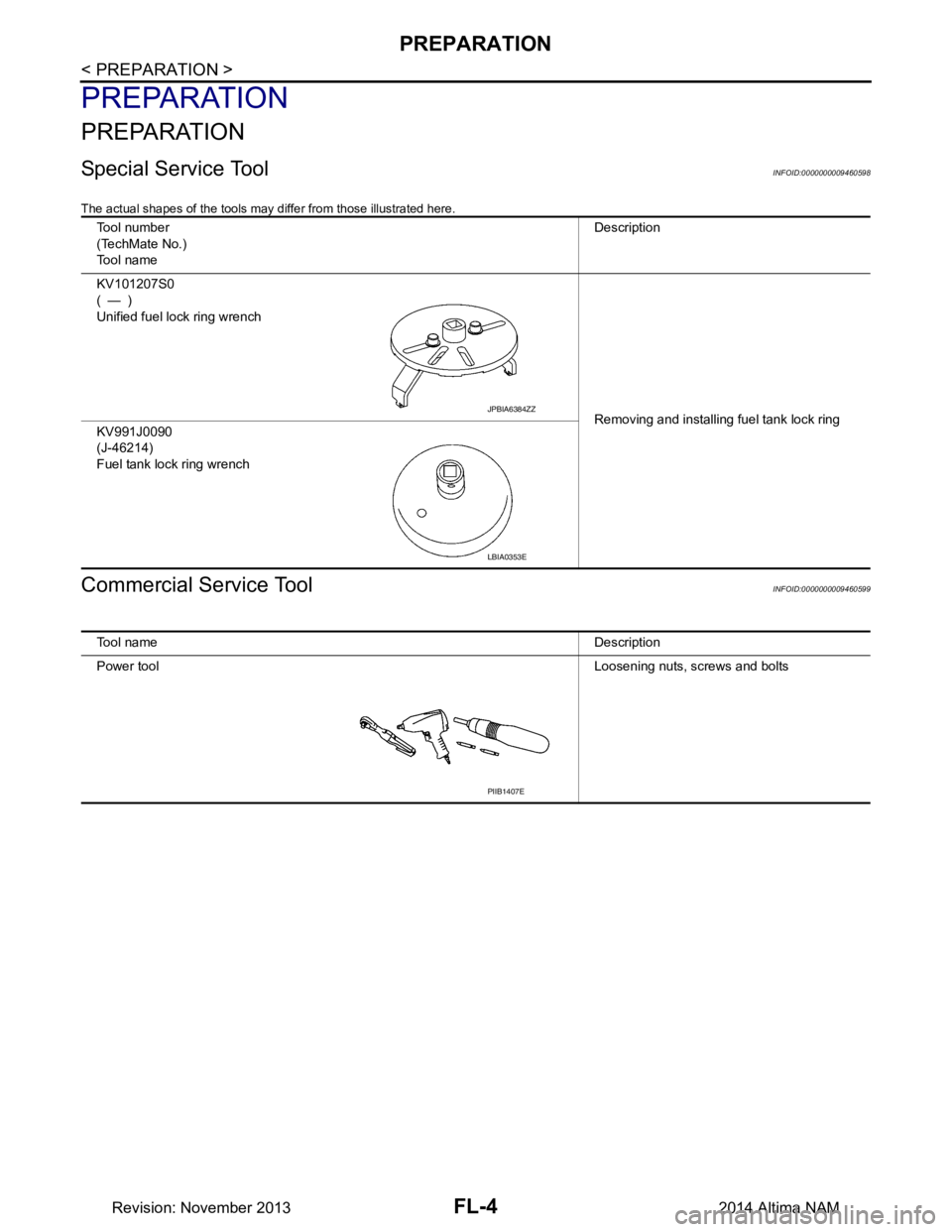
Special Service ToolINFOID:0000000009460598
The actual shapes of the tools may differ from those illustrated here.
Commercial Service ToolINFOID:0000000009460599
Tool number
(TechMate No.)
Tool name Description
KV101207S0
(—)
Unified fuel lock ring wrench
Removing and installing fuel tank lock ring
KV991J0090
(J-46214)
Fuel tank lock ring wrench
JPBIA6384ZZ
LBIA0353E
Tool name Description
Power tool Loosening nuts, screws and bolts
PIIB1407E
Revision: November 20132014 Altima NAM