2014 NISSAN TEANA engine oil
[x] Cancel search: engine oilPage 4133 of 4801

ST-30
< PERIODIC MAINTENANCE >
POWER STEERING FLUID
PERIODIC MAINTENANCE
POWER STEERING FLUID
Draining and RefillingINFOID:0000000009461266
DRAINING
1. Disconnect the high and low pressure piping from power steering gear.
2. Drain power steering fluid into a suitable container.
REFILLING
1. Fill power steering reservoir while checking power steering fluid level.
2. Bleed air from power steering hydraulic system. Refer to ST-30, "Air Bleeding Hydraulic System"
.
3. Check for power steering fluid leaks.
Air Bleeding Hydraulic SystemINFOID:0000000009461267
AIR BLEEDING HYDRAULIC SYSTEM
If air bleeding is not complete, excessive noise in the power steering oil pump will be present.
1. Make sure engine is off.
2. Turn the steering wheel from the full right stop pos ition and then to full left stop position several times.
Repeat until bubbles are no longer being generated in the reservoir.
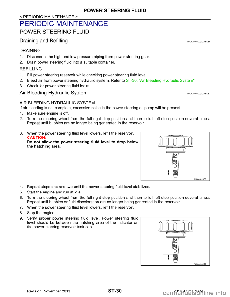
3. When the power steering fluid level lowers, refill the reservoir. CAUTION:
Do not allow the power steerin g fluid level to drop below
the hatching area.
4. Repeat steps one and two until the power steering fluid level stabilizes.
5. Start the engine and run at idle.
6. Turn the steering wheel from the full right stop pos ition and then to full left stop position several times.
Repeat until bubbles or fluid discoloration are no longer being generated in the reservoir.
7. When the power steering fluid level lowers, refill the reservoir.
8. Stop the engine.
9. Verify proper power steering fluid level. Power steering fluid level should be between the hatching area of the indicator on
the power steering reservoir tank cap.
ALGIA0125ZZ
ALGIA0125ZZ
Revision: November 20132014 Altima NAMRevision: November 20132014 Altima NAM
Page 4155 of 4801

STC-4
< SYSTEM DESCRIPTION >
COMPONENT PARTS
SYSTEM DESCRIPTION
COMPONENT PARTS
Component Parts LocationINFOID:0000000009460341
Component DescriptionINFOID:0000000009460342
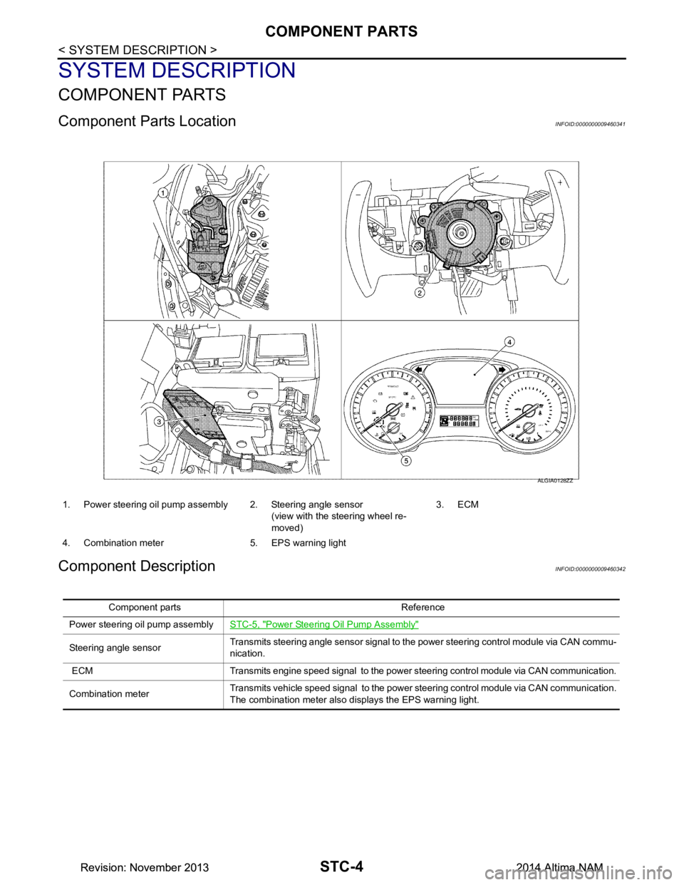
1. Power steering oil pump assembly 2. Steering angle sensor(view with the steering wheel re-
moved) 3. ECM
4. Combination meter 5. EPS warning light
ALGIA0128ZZ
Component parts Reference
Power steering oil pump assembly STC-5, "Power Steering Oil Pump Assembly"
Steering angle sensorTransmits steering angle sensor signal to the power steering control module via CAN commu-
nication.
ECM Transmits engine speed signal to the power steering control module via CAN communication.
Combination meter Transmits vehicle speed signal to the power steering control module via CAN communication.
The combination meter also di splays the EPS warning light.
Revision: November 20132014 Altima NAMRevision: November 20132014 Altima NAM
Page 4157 of 4801

STC-6
< SYSTEM DESCRIPTION >
SYSTEM
SYSTEM
HYDRAULIC PUMP ELECTRIC POWER STEERING SYSTEM
HYDRAULIC PUMP ELECTRIC POWER ST EERING SYSTEM : System Description
INFOID:0000000009460344
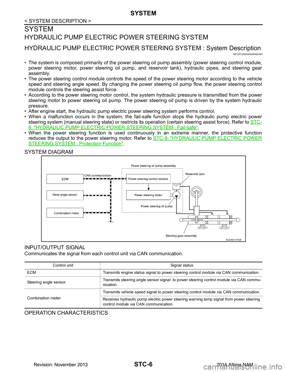
• The system is composed primarily of the power steeri ng oil pump assembly (power steering control module,
power steering motor, power steering oil pump, and reservoir tank), hydraulic pipes, and steering gear
assembly.
• The power steering control module controls the speed of the power steering motor according to the vehicle
speed and steering angle speed. By changing the power st eering oil pump flow, the power steering control
module controls the steering assist force.
• According to the power steering motor control, the sy stem hydraulic pressure is transmitted from the power
steering motor to power steering oil pump. The power steering oil pump is driven by the system hydraulic
pressure.
• After engine start, the hydraulic pump electric power steering system performs control.
• When a malfunction occurs in the system, the fail-safe function stops the hydraulic pump electric power
steering system (manual steering state) or restricts it s operation (certain steering assist force). Refer to STC-
8, "HYDRAULIC PUMP ELECTRIC POWER STEERING SYSTEM : Fail-safe".
• When the power steering function is used continuously in an extreme manner, the protective function
reduces the output to the power steering motor. Refer to STC-9, "HYDRAULIC PUMP ELECTRIC POWER
STEERING SYSTEM : Protection Function".
SYSTEM DIAGRAM
INPUT/OUTPUT SIGNAL
Communicates the signal from each control unit via CAN communication.
OPERATION CHARACTERISTICS
ALGIA0127GB
Control unit Signal status
ECM Transmits engine status signal to power steering control module via CAN communication.
Steering angle sensor Transmits steering angle sensor signal to power steering control module via CAN commu-
nication.
Combination meter Transmits vehicle speed signal to power steering control module via CAN communication.
Receives hydraulic pump electric power steering warning lamp signal from power steering
control module via CAN communication.
Revision: November 20132014 Altima NAMRevision: November 20132014 Altima NAM
Page 4182 of 4801

HYDRAULIC PUMP ELECTRIC POWER STEERING WARNING LAMP
STC-31
< DTC/CIRCUIT DIAGNOSIS >
C
D E
F
H I
J
K L
M A
B
STC
N
O P
HYDRAULIC PUMP ELECTRIC PO WER STEERING WARNING LAMP
Component Function CheckINFOID:0000000009460370
1.CHECK THE ILLUMINATION OF THE HYDRAULIC PUMP ELECTRIC POWER STEERING WARNING
LAMP
Check that the hydraulic pump electric power steering warning lamp turns ON when ignition switch turns ON.
Then, hydraulic pump electric power steering warn ing lamp turns OFF after the engine is started.
Is the inspection result normal?
YES >> Inspection End.
NO >> Perform trouble diagnosis. Refer to STC-31, "Diagnosis Procedure"
.
Diagnosis ProcedureINFOID:0000000009460371
1.PERFORM SELF-DIAGNOSIS
With CONSULT
1. Turn the ignition switch OFF to ON.
2. Perform “EPS” self-diagnosis.
Is any DTC detected?
YES >> Check the DTC. Refer to STC-13, "DTC Index".
NO >> GO TO 2.
2.CHECK HYDRAULIC PUMP ELECTRIC PO WER STEERING WARNING LAMP SIGNAL
With CONSULT
1. Turn the ignition switch ON.
2. Select “WARNING LAMP” in “DATA MONITOR” of “EPS”.
3. Check that the item in “DATA MONITOR” is “On”. CAUTION:
The engine should not be running for step 3.
4. Start the engine. CAUTION:
Never drive the vehicle during the test.
5. Check that the item in “DATA MONITOR” is “Off”.
Is the inspection result normal?
YES >> Perform the trouble diagnosis for combinat ion meter power supply circuit. Refer to MWI-58,
"COMBINATION METER : Diagnosis Procedure".
NO >> GO TO 3.
3.CHECK TERMINALS AND HARNESS CONNECTORS
Check the power steering control module pin terminal s for damage or loose connection with harness connec-
tor.
Is the inspection result normal?
YES >> Power steering control module is malfuncti oning. Replace power steering oil pump assembly.
Refer to ST-38, "Removal and Installation"
.
NO >> Repair or replace the malfunctioning component.
Revision: November 20132014 Altima NAMRevision: November 20132014 Altima NAM
Page 4216 of 4801

TM-1
TRANSMISSION & DRIVELINE
CEF
G H
I
J
K L
M
SECTION TM
A
B
TM
N
O P
CONTENTS
TRANSAXLE & TRANSMISSION
CVT: RE0F10D
PRECAUTION ................ ...............................
9
PRECAUTIONS .............................................. .....9
Precaution for Supplemental Restraint System
(SRS) "AIR BAG" and "SEAT BELT PRE-TEN-
SIONER" ............................................................. ......
9
Precaution for Procedure without Cowl Top Cover ......9
Precaution for TCM and Transaxle Assembly Re-
placement ............................................................ ......
9
General Precautions ...............................................10
On Board Diagnosis (OBD) System of CVT and
Engine ................................................................. ....
11
Removal and Installation Procedure for CVT Unit
Connector ............................................................ ....
11
PREPARATION ...........................................13
PREPARATION .............................................. ....13
Special Service Tools .......................................... ....13
Commercial Service Tools ......................................13
SYSTEM DESCRIPTION .............................14
COMPONENT PARTS ................................... ....14
CVT CONTROL SYSTEM .........................................14
CVT CONTROL SYSTEM : Component Parts Lo-
cation ................................................................... ....
14
CVT CONTROL SYSTEM : TCM ............................16
CVT CONTROL SYSTEM : Transmission Range
Switch .................................................................. ....
16
CVT CONTROL SYSTEM : Primary Speed Sen-
sor ....................................................................... ....
16
CVT CONTROL SYSTEM : Output Speed Sensor ....16
CVT CONTROL SYSTEM : In put Speed Sensor ....17
CVT CONTROL SYSTEM : CVT Fluid Tempera-
ture Sensor .......................................................... ....
17
CVT CONTROL SYSTEM : Primary Pressure
Sensor ................................................................. ....
18
CVT CONTROL SYSTEM : Secondary Pressure
Sensor ................................................................. ....
18
CVT CONTROL SYSTEM : Primary Pressure So-
lenoid Valve ......................................................... ....
19
CVT CONTROL SYSTEM : Secondary Pressure
Solenoid Valve ..................................................... ....
19
CVT CONTROL SYSTEM : Select Solenoid Valve
....
19
CVT CONTROL SYSTEM : Torque Converter
Clutch Solenoid Valve ......................................... ....
19
CVT CONTROL SYSTEM : Line Pressure Sole-
noid Valve ............................................................ ....
20
CVT CONTROL SYSTEM : Overdrive Control
Switch .................................................................. ....
20
CVT CONTROL SYSTEM : O/D OFF Indicator
Lamp .................................................................... ....
20
CVT CONTROL SYSTEM : Shift Position Indica-
tor ........................................................................ ....
20
SHIFT LOCK SYSTEM ..............................................20
SHIFT LOCK SYSTEM : Component Parts Loca-
tion ....................................................................... ....
21
STRUCTURE AND OPERATION .....................22
TRANSAXLE .......................................................... ....22
TRANSAXLE : Cross-Sectional View ......................22
TRANSAXLE : Operation Stat us .............................23
TRANSAXLE : Transaxle Me chanism .....................23
TRANSAXLE : Oil Pressure System .......................26
TRANSAXLE : Component De scription ...................27
FLUID COOLER & FLUID WARMER SYSTEM .... ....27
FLUID COOLER & FLUID WARMER SYSTEM :
System Description .............................................. ....
28
SHIFT LOCK SYSTEM ..............................................28
SHIFT LOCK SYSTEM : Syst em Description ..........28
SYSTEM ...................... ......................................30
CVT CONTROL SYSTEM ..... .....................................30
CVT CONTROL SYSTEM : S ystem Description .....30
Revision: November 20132014 Altima NAMRevision: November 20132014 Altima NAM
Page 4220 of 4801

TM-5
CEF
G H
I
J
K L
M A
B
TM
N
O P
General Specification ..........................................
..
212
Shift Characteristics ..............................................212
Stall Speed ............................................................212
Torque Converter ..................................................212
Heater Thermostat ................................................212
CVT: RE0F10E
PRECAUTION ................ ............................
213
PRECAUTIONS .............................................. ..213
Precaution for Supplemental Restraint System
(SRS) "AIR BAG" and "SEAT BELT PRE-TEN-
SIONER" ............................................................. ..
213
Precaution for Procedure without Cowl Top Cover ..213
Precaution for TCM and Transaxle Assembly Re-
placement ............................................................ ..
213
General Precautions .............................................214
On Board Diagnosis (OBD) System of CVT and
Engine ................................................................. ..
215
Removal and Installation Procedure for CVT Unit
Connector ............................................................ ..
215
PREPARATION .........................................217
PREPARATION .............................................. ..217
Special Service Tools .......................................... ..217
Commercial Service Tools ....................................217
SYSTEM DESCRIPTION ...........................218
COMPONENT PARTS ................................... ..218
CVT CONTROL SYSTEM .......................................218
CVT CONTROL SYSTEM : Component Parts Lo-
cation ................................................................... ..
218
CVT CONTROL SYSTEM : TCM ..........................219
CVT CONTROL SYSTEM : Transmission Range
Switch .................................................................. ..
219
CVT CONTROL SYSTEM : Primary Speed Sen-
sor ....................................................................... ..
219
CVT CONTROL SYSTEM : Output Speed Sensor ..220
CVT CONTROL SYSTEM : Input Speed Sensor ..220
CVT CONTROL SYSTEM : CVT Fluid Tempera-
ture Sensor .......................................................... ..
221
CVT CONTROL SYSTEM : Primary Pressure
Sensor ................................................................. ..
221
CVT CONTROL SYSTEM : Secondary Pressure
Sensor ................................................................. ..
222
CVT CONTROL SYSTEM : Primary Pressure So-
lenoid Valve ......................................................... ..
222
CVT CONTROL SYSTEM : Secondary Pressure
Solenoid Valve .................................................... ..
222
CVT CONTROL SYSTEM : Select Solenoid Valve
..
223
CVT CONTROL SYSTEM : Torque Converter
Clutch Solenoid Valve ......................................... ..
223
CVT CONTROL SYSTEM : Line Pressure Sole-
noid Valve ........................................................... ..
223
CVT CONTROL SYSTEM : Paddle Shifter ...........223
CVT CONTROL SYSTEM : Shift Position Indica-
tor ........................................................................ ..
223
SHIFT LOCK SYSTEM ............................................223
SHIFT LOCK SYSTEM : Component Parts Loca-
tion ....................................................................... ..
224
STRUCTURE AND OPERATION ...................225
TRANSAXLE .......................................................... ..225
TRANSAXLE : Cross-Sectional View ....................225
TRANSAXLE : Operation Stat us ...........................226
TRANSAXLE : Transaxle Me chanism ...................226
TRANSAXLE : Oil Pressure System .....................228
TRANSAXLE : Component De scription .................229
FLUID COOLER & FLUID WARMER SYSTEM .... ..229
FLUID COOLER & FLUID WARMER SYSTEM :
System Description .............................................. ..
230
SHIFT LOCK SYSTEM ............................................230
SHIFT LOCK SYSTEM : Syst em Description ........230
SYSTEM ...................... ....................................232
CVT CONTROL SYSTEM ..... ...................................232
CVT CONTROL SYSTEM : S ystem Description ...232
CVT CONTROL SYSTEM : Fa il-safe ....................233
CVT CONTROL SYSTEM : Pr otection Control .....236
LINE PRESSURE CONTROL ......................... .........237
LINE PRESSURE CONTROL : System Descrip-
tion ....................................................................... ..
237
SHIFT CONTROL .................................................. ..237
SHIFT CONTROL : System Description ................238
SELECT CONTROL ............................................... ..239
SELECT CONTROL : System Description ............239
LOCK-UP CONTROL ............................................ ..240
LOCK-UP CONTROL : System Description ..........240
ON BOARD DIAGNOSTIC (OBD) SYSTEM ..242
Description .............................................................242
Function of OBD ....................................................242
DIAGNOSIS SYSTEM (TCM) ..........................243
DIAGNOSIS DESCRIPTION .................................. ..243
DIAGNOSIS DESCRIPTION : 1 Trip Detection Di-
agnosis and 2 Trip Detection Diagnosis .............. ..
243
DIAGNOSIS DESCRIPTION : DTC and DTC of
1st Trip ................................................................. ..
243
DIAGNOSIS DESCRIPTION : Malfunction Indica-
tor Lamp (MIL) ..................................................... ..
243
DIAGNOSIS DESCRIPTION : Counter System ....243
CONSULT Function ............................................. ..245
ECU DIAGNOSIS INFORMATION ............251
TCM .................................................................251
Reference Value .................................................. ..251
Revision: November 20132014 Altima NAMRevision: November 20132014 Altima NAM
Page 4238 of 4801
![NISSAN TEANA 2014 Service Manual
STRUCTURE AND OPERATIONTM-23
< SYSTEM DESCRIPTION > [CVT: RE0F10D]
C
EF
G H
I
J
K L
M A
B
TM
N
O P
TRANSAXLE : Operation StatusINFOID:0000000009463981
× : Engaged or applied.
TRANSAXLE : Transaxle NISSAN TEANA 2014 Service Manual
STRUCTURE AND OPERATIONTM-23
< SYSTEM DESCRIPTION > [CVT: RE0F10D]
C
EF
G H
I
J
K L
M A
B
TM
N
O P
TRANSAXLE : Operation StatusINFOID:0000000009463981
× : Engaged or applied.
TRANSAXLE : Transaxle](/manual-img/5/57390/w960_57390-4237.png)
STRUCTURE AND OPERATIONTM-23
< SYSTEM DESCRIPTION > [CVT: RE0F10D]
C
EF
G H
I
J
K L
M A
B
TM
N
O P
TRANSAXLE : Operation StatusINFOID:0000000009463981
× : Engaged or applied.
TRANSAXLE : Transaxle MechanismINFOID:0000000009463982
TORQUE CONVERTER (WITH LOCK-UP FUNCTION)
In the same way as a conventional A/T, the torque c onverter is a system that increases the engine torque and
transmits the torque to the transaxle. A symmetr ical 3-element, 1-stage, 2-phase type is used here.
OIL PUMP
Utilizes a vane-type oil pump that is driven by the engi ne through the oil pump drive chain in order to increase
efficiency of pump discharge volume in low-speed zone and optimize pump discharge volume in high-speed
zone. Discharged oil from oil pump is transmitted to contro l valve. It is used as the oil of primary and second-
ary pulley operation, the oil of clutch operation, and the lubricant for each part.
PLANETARY GEAR
• A planetary gear type of forward/reverse selector me chanism is installed between the torque converter and
primary pulley.
• The power from the torque converter is input via the i nput shaft, operating a wet multi-plate clutch by means
of hydraulic pressure to switch between forward and reverse driving.
Operation of Planetary gear
BELT & PULLEY
It is composed of a pair of pulleys (the groove width is changed freely in the axial direction) and the steel belt
(the steel plates are placed conti nuously and the belt is guided with the multilayer steel rings on both sides).
Selector lever
position Parking mech-
anism Forward
clutch Reverse brake Primary pulley Secondary
pulley Steel belt Final drive
P ×
R ×××××
N
D × ××××
DS × ××××
JSDIA2426GB
Revision: November 20132014 Altima NAMRevision: November 20132014 Altima NAM
Page 4242 of 4801
![NISSAN TEANA 2014 Service Manual
STRUCTURE AND OPERATIONTM-27
< SYSTEM DESCRIPTION > [CVT: RE0F10D]
C
EF
G H
I
J
K L
M A
B
TM
N
O P
TRANSAXLE : Component DescriptionINFOID:0000000009463984
FLUID COOLER & FLUID WARMER SYSTEM
Part na NISSAN TEANA 2014 Service Manual
STRUCTURE AND OPERATIONTM-27
< SYSTEM DESCRIPTION > [CVT: RE0F10D]
C
EF
G H
I
J
K L
M A
B
TM
N
O P
TRANSAXLE : Component DescriptionINFOID:0000000009463984
FLUID COOLER & FLUID WARMER SYSTEM
Part na](/manual-img/5/57390/w960_57390-4241.png)
STRUCTURE AND OPERATIONTM-27
< SYSTEM DESCRIPTION > [CVT: RE0F10D]
C
EF
G H
I
J
K L
M A
B
TM
N
O P
TRANSAXLE : Component DescriptionINFOID:0000000009463984
FLUID COOLER & FLUID WARMER SYSTEM
Part name Function
Torque converter Increases engine torque and transmits it to the transaxle.
Oil pump Utilizes a vane-type oil pump that is driven by the engine through the oil pump drive chain in order to
increase efficiency of pump discharge volume in low-speed zone and optimize pump discharge volume
in high-speed zone. Discharged oil from oil pump is tr ansmitted to control valve. It is used as the oil of
primary and secondary pulley operation, the oil of clutch operation, and the lubricant for each part.
Forward clutch The forward clutch is wet and multiple plate type clutch that consists of clutch drum, piston, drive plate,
and driven plate. It is a clutch to move the vehicle forward by activating piston hydraulically, engaging
plates, and directly connecting sun gear and input shaft.
Reverse brake The reverse brake is a wet multiple-plate type brake that consists of transaxle case, piston, drive plate,
and driven plate. It is a brake to move the vehicle in reverse by activating piston hydraulically, engaging
plates, and fixing planetary gear.
Internal gear The internal gear is directly connected to forward clutch drum. It is a gear that moves the outer edge of
pinion planet of planet carrier. It transmits power to move the vehicle in reverse when the planet carrier
is fixed.
Planet carrier Composed of a carrier, pinion planet, and pinion shaft. This gear fixes and releases the planet carrier in
order to switch between forward and reverse driving.
Sun gear Sun gear is a set part with planet carrier and internal gear. It transmits transmitted force to primary fixed
sheave. It rotates in forward or reverse direction according to activation of either forward clutch or re-
verse brake.
Input shaft The input shaft is directly connected to forward clutch drum and transmits traction force from torque con-
verter. In shaft center, there are holes for hydraulic distribution to primary pulley and hydraulic distribution
for lockup ON/OFF.
Primary pulley It is composed of a pair of pulleys (the groove width is changed freely in the axial direction) and the steel belt. The groove width changes according to wrapping radius of steel belt and pulley from low status to
overdrive status continuously with non-step. It is controlled with the oil pressures of primary pulley and
secondary pulley.
Secondary pulley
Steel belt
Manual shaft When the manual shaft is in the P position, the parking rod that is linked to the manual shaft rotates the
parking pole. When the parking pole rotates, it engages with the parking gear, fixing the parking gear. As
a result, the secondary pulley that is integrated with the parking gear is fixed.
Parking rod
Parking pawl
Parking gear
Output gear
The deceleration gears are composed of 2 stages: primary deceleration (output gear, idler gear pair) and
secondary deceleration (reduction gear, final gear pair). All of these gears are helical gears.
Idler gear
Reduction gear
Differential
Torque converter regulator
valve Adjusts the feed pressure to the torque converter to the optimum pressure corresponding to the driving
condition.
Pressure regulator valve Adjusts the discharge pressure from the oil pump to the optimum pressure (line pressure) corresponding
to the driving condition.
Torque converter clutch
control valve Adjusts the torque converter engage and disengage pressures.
Manual valve Distributes the clutch operation pressure to each circuit according to the selector lever position.
Secondary reducing valve Reduces line pressure and adjusts secondary pressure.
Primary reducing valve Reduces line pressure and adjusts primary pressure.
Pilot valve A Reduces line pressure and adjusts pilot pressure to the solenoid valves listed below.
• Primary pressure solenoid valve
• Secondary pressure solenoid valve
• Select solenoid valve
• Line pressure solenoid valve
Pilot valve B Reduces pilot pressure and adjusts pilot pressure to the torque converter clutch solenoid valve.
Revision: November 20132014 Altima NAMRevision: November 20132014 Altima NAM