2014 NISSAN TEANA engine oil
[x] Cancel search: engine oilPage 3734 of 4801
SERVICE DATA AND SPECIFICATIONS (SDS)RSU-17
< SERVICE DATA AND SPECIFICATIONS (SDS)
C
D
F
G H
I
J
K L
M A
B
RSU
N
O P
SERVICE DATA AND SPECIFICATIONS (SDS)
SERVICE DATA AND SPECIFICATIONS (SDS)
General Specification (Rear)INFOID:0000000009464468
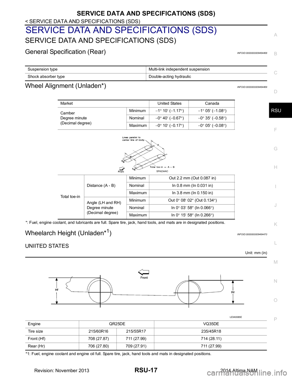
Wheel Alignment (Unladen*)INFOID:0000000009464469
*: Fuel, engine coolant, and lubricants are full. Spare tire, jack, hand tools, and mats are in designated positions.
Wheelarch Height (Unladen*1)INFOID:0000000009464470
UNIITED STATES
Unit: mm (in)
*1: Fuel, engine coolant and engine oil full. Spare tire, jack, hand tools and mats in designated positions. Suspension type Multi-link independent suspension
Shock absorber type Double-acting hydraulic
Market United States Canada
Camber
Degree minute
(Decimal degree) Minimum
−1° 10 ′ ( −1.17 °) −1 ° 05 ′ ( −1.08 °)
Nominal −0° 40 ′ ( −0.67 °) −0 ° 35 ′ ( −0.58 °)
Maximum −0° 10 ′ ( −0.17 °) −0 ° 05 ′ ( −0.08 °)
Total toe-in Distance (A - B)
Minimum Out 2.2 mm (Out 0.087 in)
Nominal In 0.8 mm (In 0.031 in)
Maximum In 3.8 mm (In 0.150 in)
Angle (LH and RH)
Degree minute
(Decimal degree) Minimum Out 0
° 08 ′ 02 ″ (Out 0.134 °)
Nominal In 0 ° 03 ′ 58 ″ (In 0.066 °)
Maximum In 0 ° 15 ′ 58 ″ (In 0.266 °)
SFA234AC
Engine QR25DE VQ35DE
Tire size 215/60R16 215/55R17 235/45R18
Front (Hf) 708 (27.87) 711 (27.99) 714 (28.11)
Rear (Hr) 706 (27.80) 709 (27.91) 711 (27.99)
LEIA0085E
Revision: November 20132014 Altima NAM
Page 3735 of 4801
RSU-18
< SERVICE DATA AND SPECIFICATIONS (SDS)
SERVICE DATA AND SPECIFICATIONS (SDS)
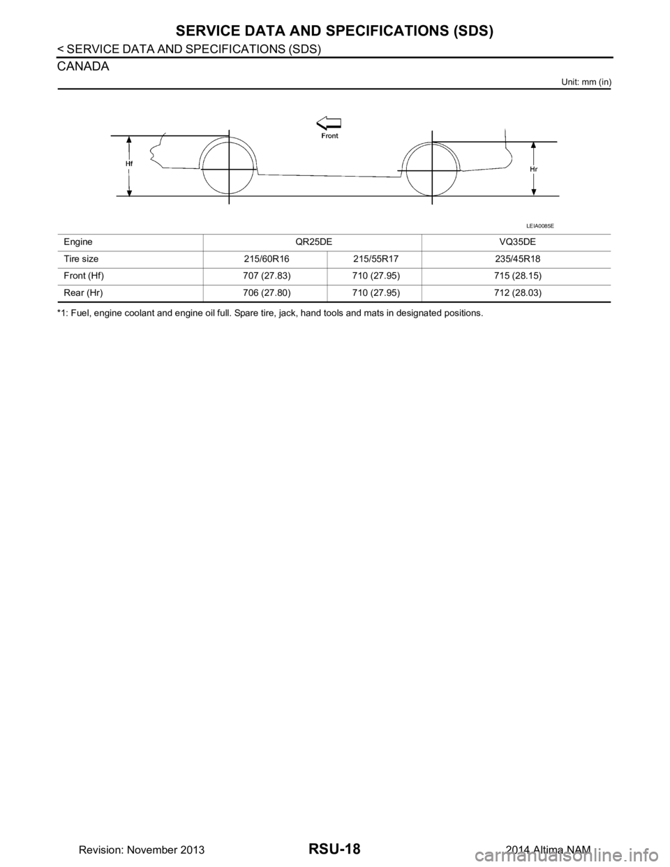
CANADA
Unit: mm (in)
*1: Fuel, engine coolant and engine oil full. Spare tire, jack, hand tools and mats in designated positions.Engine QR25DE VQ35DE
Tire size 215/60R16 215/55R17 235/45R18
Front (Hf) 707 (27.83) 710 (27.95) 715 (28.15)
Rear (Hr) 706 (27.80) 710 (27.95) 712 (28.03)
LEIA0085E
Revision: November 20132014 Altima NAM
Page 3737 of 4801
SB-2
< PRECAUTION >
PRECAUTIONS
PRECAUTION
PRECAUTIONS
Precaution for Supplemental Restraint System (SRS) "AIR BAG" and "SEAT BELT
PRE-TENSIONER"
INFOID:0000000009951757
The Supplemental Restraint System such as “A IR BAG” and “SEAT BELT PRE-TENSIONER”, used along
with a front seat belt, helps to reduce the risk or severi ty of injury to the driver and front passenger for certain
types of collision. Information necessary to service the system safely is included in the SR and SB section of
this Service Manual.
WARNING:
• To avoid rendering the SRS inopera tive, which could increase the risk of personal injury or death in
the event of a collision which would result in air bag inflation, all maintenance must be performed by
an authorized NISS AN/INFINITI dealer.
• Improper maintenance, including in correct removal and installation of the SRS, can lead to personal
injury caused by unintent ional activation of the system. For re moval of Spiral Cable and Air Bag
Module, see the SR section.
• Do not use electrical test equipmen t on any circuit related to the SRS unless instructed to in this
Service Manual. SRS wiring harn esses can be identified by yellow and/or orange harnesses or har-
ness connectors.
PRECAUTIONS WHEN USING POWER TOOLS (AIR OR ELECTRIC) AND HAMMERS
WARNING:
• When working near the Airbag Diagnosis Sensor Unit or other Airbag System sensors with the Igni-
tion ON or engine running, DO NOT use air or electri c power tools or strike near the sensor(s) with a
hammer. Heavy vibration could activate the sensor( s) and deploy the air bag(s), possibly causing
serious injury.
• When using air or electric power tools or hammers , always switch the Ignition OFF, disconnect the
battery and wait at least three minutes before performing any service.
Precaution for Seat Belt ServiceINFOID:0000000009462957
CAUTION:
• Before removing the seat belt pre-tensioner assembl y, turn the ignition switch OFF, disconnect both
battery terminals and wait at least three minutes. For approximately three minutes after the battery
terminals have been removed, it is still possible for the air bag and seat belt pre-tensioner to deploy.
Therefore, do not attempt work on any SRS conn ectors or wires until at least three minutes have
passed.
• After replacing or reinstalling seat belt pre -tensioner assembly or reconnecting seat belt pre-ten-
sioner assembly connector, make sure entire SRS operates properly. Refer to SRC-15, "SRS Opera-
tion Check".
• Do not disassemble buckle or seat belt assembly.
• Replace anchor bolts if th ey are deformed or worn out.
• Do not oil tongue or buckle.
• If any component of seat belt assembly is questionable, do not re pair. Replace the whole seat belt
assembly.
• If webbing is cut, frayed or damaged, replace seat belt assembly.
• When replacing seat belt assembly, use a genuine NISSAN seat belt assembly.
Precaution for WorkINFOID:0000000009462958
• When removing or disassembling each component, be careful not to damage or deform it. If a component may be subject to interference, be sure to protect it with a shop cloth.
• When removing (disengaging) components with a screwdriver or similar tool, be sure to wrap the component with a shop cloth or vinyl tape to protect it.
• Protect the removed parts with a s hop cloth and prevent them from being dropped.
• Replace a deformed or damaged clip.
• If a part is specified as a non-reusable part, always replace it with a new one.
• Be sure to tighten bolts and nuts securely to the specified torque.
• After installation is complete, be sure to check that each part works properly.
Revision: November 20132014 Altima NAM
Page 3751 of 4801

SE-2
< PRECAUTION >
PRECAUTIONS
PRECAUTION
PRECAUTIONS
Precaution for Supplemental Restraint System (SRS) "AIR BAG" and "SEAT BELT
PRE-TENSIONER"
INFOID:0000000009951559
The Supplemental Restraint System such as “A IR BAG” and “SEAT BELT PRE-TENSIONER”, used along
with a front seat belt, helps to reduce the risk or severi ty of injury to the driver and front passenger for certain
types of collision. Information necessary to service the system safely is included in the SR and SB section of
this Service Manual.
WARNING:
• To avoid rendering the SRS inopera tive, which could increase the risk of personal injury or death in
the event of a collision which would result in air bag inflation, all maintenance must be performed by
an authorized NISS AN/INFINITI dealer.
• Improper maintenance, including in correct removal and installation of the SRS, can lead to personal
injury caused by unintent ional activation of the system. For re moval of Spiral Cable and Air Bag
Module, see the SR section.
• Do not use electrical test equipmen t on any circuit related to the SRS unless instructed to in this
Service Manual. SRS wiring harn esses can be identified by yellow and/or orange harnesses or har-
ness connectors.
PRECAUTIONS WHEN USING POWER TOOLS (AIR OR ELECTRIC) AND HAMMERS
WARNING:
• When working near the Airbag Diagnosis Sensor Unit or other Airbag System sensors with the Igni-
tion ON or engine running, DO NOT use air or electri c power tools or strike near the sensor(s) with a
hammer. Heavy vibration could activate the sensor( s) and deploy the air bag(s), possibly causing
serious injury.
• When using air or electric power tools or hammers , always switch the Ignition OFF, disconnect the
battery and wait at least three minutes before performing any service.
Precaution for WorkINFOID:0000000009462924
• When removing or disassembling each component, be careful not to damage or deform it. If a component may be subject to interference, be sure to protect it with a shop cloth.
• When removing (disengaging) components with a screwdriver or similar tool, be sure to wrap the component with a shop cloth or vinyl tape to protect it.
• Protect the removed parts with a s hop cloth and prevent them from being dropped.
• Replace a deformed or damaged clip.
• If a part is specified as a non-reusable part, always replace it with a new one.
• Be sure to tighten bolts and nuts securely to the specified torque.
• After installation is complete, be sure to check that each part works properly.
• Follow the steps below to clean components:
- Water soluble dirt:
• Dip a soft cloth into lukewarm water, wring the water out of the cloth and wipe the dirty area.
• Then rub with a soft, dry cloth.
- Oily dirt:
• Dip a soft cloth into lukewarm water with mild detergent (concentration: within 2 to 3%) and wipe the dirty area.
• Then dip a cloth into fresh water, wring the water out of the cloth and wipe the detergent off.
• Then rub with a soft, dry cloth.
- Do not use organic solvent such as thinner, benzene, alcohol or gasoline.
- For genuine leather seats, use a genuine leather seat cleaner.
Revision: November 20132014 Altima NAMRevision: November 20132014 Altima NAM
Page 3829 of 4801

SEC-4
< PRECAUTION >
PRECAUTIONS
PRECAUTION
PRECAUTIONS
Precaution for Supplemental Restraint System (SRS) "AIR BAG" and "SEAT BELT
PRE-TENSIONER"
INFOID:0000000009951563
The Supplemental Restraint System such as “A IR BAG” and “SEAT BELT PRE-TENSIONER”, used along
with a front seat belt, helps to reduce the risk or severi ty of injury to the driver and front passenger for certain
types of collision. Information necessary to service the system safely is included in the SR and SB section of
this Service Manual.
WARNING:
• To avoid rendering the SRS inopera tive, which could increase the risk of personal injury or death in
the event of a collision which would result in air bag inflation, all maintenance must be performed by
an authorized NISS AN/INFINITI dealer.
• Improper maintenance, including in correct removal and installation of the SRS, can lead to personal
injury caused by unintent ional activation of the system. For re moval of Spiral Cable and Air Bag
Module, see the SR section.
• Do not use electrical test equipmen t on any circuit related to the SRS unless instructed to in this
Service Manual. SRS wiring harn esses can be identified by yellow and/or orange harnesses or har-
ness connectors.
PRECAUTIONS WHEN USING POWER TOOLS (AIR OR ELECTRIC) AND HAMMERS
WARNING:
• When working near the Airbag Diagnosis Sensor Unit or other Airbag System sensors with the Igni-
tion ON or engine running, DO NOT use air or electri c power tools or strike near the sensor(s) with a
hammer. Heavy vibration could activate the sensor( s) and deploy the air bag(s), possibly causing
serious injury.
• When using air or electric power tools or hammers , always switch the Ignition OFF, disconnect the
battery and wait at least three minutes before performing any service.
Precaution for WorkINFOID:0000000009461062
• When removing or disassembling each component, be careful not to damage or deform it. If a component may be subject to interference, be sure to protect it with a shop cloth.
• When removing (disengaging) components with a screwdriver or similar tool, be sure to wrap the component with a shop cloth or vinyl tape to protect it.
• Protect the removed parts with a s hop cloth and prevent them from being dropped.
• Replace a deformed or damaged clip.
• If a part is specified as a non-reusable part, always replace it with a new one.
• Be sure to tighten bolts and nuts securely to the specified torque.
• After installation is complete, be sure to check that each part works properly.
• Follow the steps below to clean components:
- Water soluble dirt:
• Dip a soft cloth into lukewarm water, wring the water out of the cloth and wipe the dirty area.
• Then rub with a soft, dry cloth.
- Oily dirt:
• Dip a soft cloth into lukewarm water with mild detergent (concentration: within 2 to 3%) and wipe the dirty area.
• Then dip a cloth into fresh water, wring the water out of the cloth and wipe the detergent off.
• Then rub with a soft, dry cloth.
- Do not use organic solvent such as thinner, benzene, alcohol or gasoline.
- For genuine leather seats, use a genuine leather seat cleaner.
Revision: November 20132014 Altima NAMRevision: November 20132014 Altima NAM
Page 4106 of 4801
PRECAUTIONSST-3
< PRECAUTION >
C
D E
F
H I
J
K L
M A
B
ST
N
O P
PRECAUTION
PRECAUTIONS
Precaution for Supplemental Restraint System (SRS) "AIR BAG" and "SEAT BELT
PRE-TENSIONER"
INFOID:0000000009951723
The Supplemental Restraint System such as “A IR BAG” and “SEAT BELT PRE-TENSIONER”, used along
with a front seat belt, helps to reduce the risk or severi ty of injury to the driver and front passenger for certain
types of collision. Information necessary to service t he system safely is included in the SR and SB section of
this Service Manual.
WARNING:
• To avoid rendering the SRS inoper ative, which could increase the risk of personal injury or death in
the event of a collision which would result in air bag inflation, all maintenance must be performed by
an authorized NISSAN/INFINITI dealer.
• Improper maintenance, including in correct removal and installation of the SRS, can lead to personal
injury caused by unintentional act ivation of the system. For removal of Spiral Cable and Air Bag
Module, see the SR section.
• Do not use electrical test equipm ent on any circuit related to the SRS unless instructed to in this
Service Manual. SRS wiring harnesses can be identi fied by yellow and/or orange harnesses or har-
ness connectors.
PRECAUTIONS WHEN USING POWER TOOLS (AIR OR ELECTRIC) AND HAMMERS
WARNING:
• When working near the Airbag Diagnosis Sensor Un it or other Airbag System sensors with the Igni-
tion ON or engine running, DO NOT use air or el ectric power tools or strike near the sensor(s) with a
hammer. Heavy vibration could activate the sensor( s) and deploy the air bag(s), possibly causing
serious injury.
• When using air or electric power tools or hammers , always switch the Ignition OFF, disconnect the
battery and wait at least three mi nutes before performing any service.
Precaution for Steering SystemINFOID:0000000009461240
• Before disassembly, thoroughly clean the outside of the unit.
• Disassembly should be done in a clean work area. It is im portant to prevent the internal parts from becoming
contaminated by dirt or other foreign matter.
• For easier and proper assembly, place disassembled parts in order on a parts rack.
• Use nylon cloth or paper towels to clean the parts; common shop rags can leave lint that might interfere with
their operation.
• Before inspection or reassembly, carefully clean al l parts with a general purpose, non-flammable solvent.
• Before assembly, apply a coat of recommended Genuine NISSAN PSF or equivalent to hydraulic parts.
Petroleum jelly may be applied to O-rings and seals. Do not use any grease.
• Replace all gaskets, seals and O-rings. Avoid damaging O-rings, seals and gaskets during installation. Per- form functional tests whenever designated.
Precaution for WorkINFOID:0000000009461241
• When removing or disassembling each component, be ca reful not to damage or deform it. If a component
may be subject to interference, be sure to protect it with a shop cloth.
• When removing (disengaging) components with a screwdriver or similar tool, be sure to wrap the component
with a shop cloth or vinyl tape to protect it.
• Protect the removed parts with a shop cloth and prevent them from being dropped.
• Replace a deformed or damaged clip.
• If a part is specified as a non-reusabl e part, always replace it with a new one.
• Be sure to tighten bolts and nuts securely to the specified torque.
• After installation is complete, be sure to check that each part works properly.
• Follow the steps below to clean components:
- Water soluble dirt:
• Dip a soft cloth into lukewarm water, wring the water out of the cloth and wipe the dirty area.
• Then rub with a soft, dry cloth.
-Oily dirt:
Revision: November 20132014 Altima NAMRevision: November 20132014 Altima NAM
Page 4118 of 4801
POWER STEERING FLUIDST-15
< BASIC INSPECTION >
C
D E
F
H I
J
K L
M A
B
ST
N
O P
POWER STEERING FLUID
InspectionINFOID:0000000009461251
FLUID LEVEL
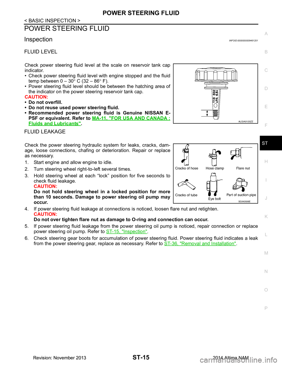
Check power steering fluid level at the scale on reservoir tank cap
indicator.
• Check power steering fluid level with engine stopped and the fluid temp between 0 – 30 ° C (32 – 86 ° F).
• Power steering fluid level should be between the hatching area of the indicator on the power steering reservoir tank cap.
CAUTION:
• Do not overfill.
• Do not reuse used power steering fluid.
• Recommended power steering fluid is Genuine NISSAN E-
PSF or equivalent. Refer to MA-11, "FOR USA AND CANADA :
Fluids and Lubricants".
FLUID LEAKAGE
Check the power steering hydraulic system for leaks, cracks, dam-
age, loose connections, chafing or det erioration. Repair or replace
as necessary.
1. Start engine and allow engine to idle.
2. Turn steering wheel right-to-left several times.
3. Hold steering wheel at each “lock” position for five seconds to check fluid leakage.
CAUTION:
Do not hold steering wheel in a locked position for more
than 10 seconds. Damage to power steering oil pump may
occur.
4. If power steering fluid leakage at connections is noticed, loosen flare nut and retighten.
CAUTION:
Do not over tighten flare nut as damage to O-ring and connection can occur.
5. If power steering fluid leakage from the power steer ing oil pump is noticed, repair connection or replace
power steering oil pump. Refer to ST-15, "Inspection"
.
6. Check steering gear boots for accumulation of power st eering fluid. Power steering fluid indicates a leak
from the power steering gear, replace as necessary. Refer to ST-36, "Removal and Installation"
.
ALGIA0125ZZ
SGIA0506E
Revision: November 20132014 Altima NAMRevision: November 20132014 Altima NAM
Page 4122 of 4801
POWER STEERING OIL PUMPST-19
< BASIC INSPECTION >
C
D E
F
H I
J
K L
M A
B
ST
N
O P
POWER STEERING OIL PUMP
InspectionINFOID:0000000009461254
RELIEF OIL PRESSURE
CAUTION:
Make sure that belt tension is normal be fore starting the following procedure.
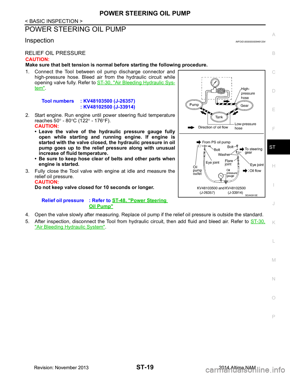
1. Connect the Tool between oil pump discharge connector and high-pressure hose. Bleed air from the hydraulic circuit while
opening valve fully. Refer to ST-30, "Air Bleeding Hydraulic Sys-
tem".
2. Start engine. Run engine until power steering fluid temperature reaches 50 ° - 80 °C (122 ° - 176 °F).
CAUTION:
• Leave the valve of the hydraulic pressure gauge fully open while starting and ru nning engine. If engine is
started with the valve closed, th e hydraulic pressure in oil
pump goes up to the relief pressure along with unusual
increase of fluid temperature.
• Be sure to keep hose clear of belts and other parts when engine is started.
3. Fully close the Tool valve with engine at idle and measure the relief oil pressure.
CAUTION:
Do not keep valve closed for 10 seconds or longer.
4. Open the valve slowly after measuring. Replace oil pump if the relief oil pressure is outside the standard.
5. After inspection, disconnect the Tool from hydraul ic circuit, then add fluid and bleed air. Refer to ST-30,
"Air Bleeding Hydraulic System".
Tool numbers : KV48103500 (J-26357)
: KV48102500 (J-33914)
Relief oil pressure : Refer to ST-48, "Power Steering
Oil Pump"
SGIA0915E
Revision: November 20132014 Altima NAMRevision: November 20132014 Altima NAM