2014 NISSAN TEANA oil change
[x] Cancel search: oil changePage 3195 of 4801
RECOMMENDED FLUIDS AND LUBRICANTSMA-11
< PERIODIC MAINTENANCE >
C
D E
F
G H
I
J
K L
M B
MA
N
O A
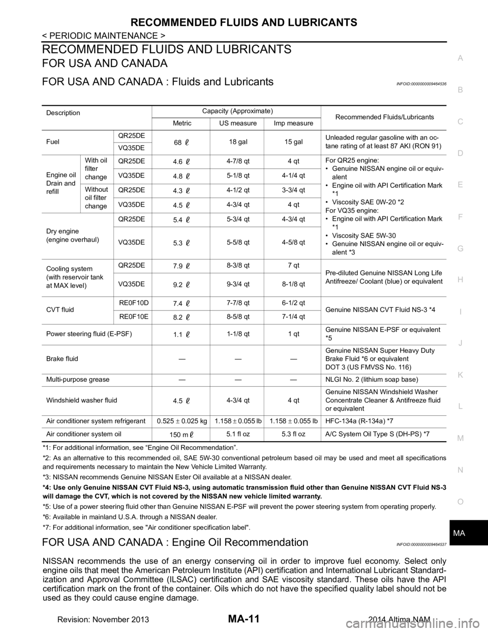
RECOMMENDED FLUIDS AND LUBRICANTS
FOR USA AND CANADA
FOR USA AND CANADA :
Fluids and LubricantsINFOID:0000000009464536
*1: For additional information, see “Engine Oil Recommendation”.
*2: As an alternative to this recommended oil, SAE 5W-30 conventional petroleum based oil may be used and meet all specificatio ns
and requirements necessary to maintain the New Vehicle Limited Warranty.
*3: NISSAN recommen ds Genuine NISSAN Ester Oil av ailable at a NISSAN dealer.
*4: Use only Genuine NISSAN CVT Fluid NS -3, using automatic transmission fluid other than Genuine NISSAN CVT Fluid NS-3
will damage the CVT, which is not covered by the NISSAN new vehicle limited warranty.
*5: Use of a power steering fluid other than Genuine NISSAN E-PSF will prevent the power steering system from operating properly.
*6: Available in mainland U. S.A. through a NISSAN dealer.
*7: For additional information, see "Air conditioner specification label".
FOR USA AND CANADA : En gine Oil RecommendationINFOID:0000000009464537
NISSAN recommends the use of an energy conserving o il in order to improve fuel economy. Select only
engine oils that meet the American Petroleum Institut e (API) certification and International Lubricant Standard-
ization and Approval Committee (ILSAC) certificati on and SAE viscosity standard. These oils have the API
certification mark on the front of the container. Oils which do not have the specified quality label should not be
used as they could cause engine damage.
Description Capacity (Approximate)
Recommended Fluids/Lubricants
Metric US measure Imp measure
Fuel QR25DE
68 18 gal 15 gal Unleaded regular gasoline with an oc-
tane rating of at least 87 AKI (RON 91)
VQ35DE
Engine oil
Drain and
refill With oil
filter
change QR25DE
4.6 4-7/8 qt 4 qt For QR25 engine:
• Genuine NISSAN engine oil or equiv- alent
• Engine oil with API Certification Mark
*1
• Viscosity SAE 0W-20 *2
For VQ35 engine:
• Engine oil with API Certification Mark
*1
• Viscosity SAE 5W-30
• Genuine NISSAN engine oil or equiv-
alent *3
VQ35DE
4.8 5-1/8 qt 4-1/4 qt
Without
oil filter
change QR25DE
4.3 4-1/2 qt 3-3/4 qt
VQ35DE 4.5 4-3/4 qt 4 qt
Dry engine
(engine overhaul) QR25DE
5.4 5-3/4 qt 4-3/4 qt
VQ35DE 5.3 5-5/8 qt 4-5/8 qt
Cooling system
(with reservoir tank
at MAX level) QR25DE
7.9 8-3/8 qt 7 qt
Pre-diluted Genuine NISSAN Long Life
Antifreeze/ Coolant (blue) or equivalent
VQ35DE 9.2 9-3/4 qt 8-1/8 qt
CVT fluid RE0F10D
7.4 7-7/8 qt 6-1/2 qt
Genuine NISSAN CVT Fluid NS-3 *4
RE0F10E 8.2 8-5/8 qt 7-1/4 qt
Power steering fluid (E-PSF) 1.1 1-1/8 qt 1 qt Genuine NISSAN E-PSF or equivalent
*5
Brake fluid — — — Genuine NISSAN Super Heavy Duty
Brake Fluid *6 or equivalent
DOT 3 (US FMVSS No. 116)
Multi-purpose grease — — — NLGI No. 2 (lithium soap base)
Windshield washer fluid 4.5 4-3/4 qt 4 qt Genuine NISSAN Windshield Washer
Concentrate Cleaner & Antifreeze fluid
or equivalent
Air conditioner system refrigerant 0.525 ± 0.025 kg 1.158 ± 0.055 lb 1.158 ± 0.055 lb HFC-134a (R-134a) *7
Air conditioner system oil 150 m5.1 fl oz 5.3 fl oz A/C System Oil Type S (DH-PS) *7
Revision: November 20132014 Altima NAM
Page 3217 of 4801
CHASSIS AND BODY MAINTENANCEMA-33
< PERIODIC MAINTENANCE >
C
D E
F
G H
I
J
K L
M B
MA
N
O A
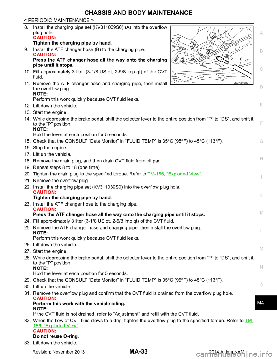
8. Install the charging pipe set (KV311039S0) (A) into the overflow
plug hole.
CAUTION:
Tighten the charging pipe by hand.
9. Install the ATF changer hose (B) to the charging pipe. CAUTION:
Press the ATF changer hose all the way onto the charging
pipe until it stops.
10. Fill approximately 3 liter (3-1/8 US qt, 2-5/8 lmp qt) of the CVT fluid.
11. Remove the ATF changer hose and charging pipe, then install the overflow plug.
NOTE:
Perform this work quickly because CVT fluid leaks.
12. Lift down the vehicle.
13. Start the engine.
14. While depressing the brake pedal, shift the selector leve r to the entire position from “P” to “DS”, and shift it
to the “P” position.
NOTE:
Hold the lever at each position for 5 seconds.
15. Check that the CONSULT “Data Monitor” in “FLUID TEMP” is 35°C (95 °F) to 45 °C (113 °F).
16. Stop the engine.
17. Lift up the vehicle.
18. Remove the drain plug, and then drain CVT fluid from oil pan.
19. Repeat steps 8 to 18 (one time).
20. Tighten the drain plug to the specified torque. Refer to TM-186, "Exploded View"
.
21. Remove the overflow plug.
22. Install the charging pipe set (KV311039S0) into the overflow plug hole. CAUTION:
Tighten the charging pipe by hand.
23. Install the ATF changer hose to the charging pipe. CAUTION:
Press the ATF changer hose all the way onto the charging pipe until it stops.
24. Fill approximately 3 liter (3-1/8 US qt, 2-5/8 lmp qt) of the CVT fluid.
25. Remove the ATF changer hose and charging pipe, then install the overflow plug. NOTE:
Perform this work quickly because CVT fluid leaks.
26. Lift down the vehicle.
27. Start the engine.
28. While depressing the brake pedal, shift the selector leve r to the entire position from “P” to “DS”, and shift it
to the “P” position.
NOTE:
Hold the lever at each position for 5 seconds.
29. Check that the CONSULT “Data Monitor” in “FLUID TEMP” is 35°C (95 °F) to 45 °C (113 °F).
30. Lift up the vehicle.
31. Remove the overflow plug and confirm that the CV T fluid is drained from the overflow plug hole.
CAUTION:
Perform this work with the vehicle idling.
NOTE:
If the CVT fluid is not drained, refer to “Adjustment” and refill with the CVT fluid.
32. When the flow of CVT fluid slows to a drip, tighten the overflow plug to the specified torque. Refer to TM-
186, "Exploded View".
CAUTION:
Do not reuse O-ring.
33. Lift down the vehicle.
JSDIA3713ZZ
Revision: November 20132014 Altima NAM
Page 3218 of 4801
MA-34
< PERIODIC MAINTENANCE >
CHASSIS AND BODY MAINTENANCE
34. Select “Data Monitor” in “TRANSMISSION” using CONSULT.
35. Select “CONFORM CVTF DETERIORTN”.
36. Select “Erase”.
37. Stop the engine.
CVT FLUID : AdjustmentINFOID:0000000009464569
CAUTION:
• During adjustment of the CVT fluid level, check CO NSULT so that the oil temperature may be main-
tained from 35 to 45 °C (95 to 113 °F).
• During adjustment of the CVT fluid level, check that the engine speed is maintaining 500 rpm.
• Use caution when looking into the drain hole as th ere is a risk of dripping fluid entering the eye.
1. Check that the selector lever is in the “P ” position, then completely engage the parking brake.
2. Start the engine.
3. Adjust the CVT fluid temperature to be approximately 40 °C (104 °F).
NOTE:
The CVT fluid is largely affected by temperature. Therefore be sure to use CONSULT and check the
“FLUID TEMP” under “TRANSMISSION” in “Data Monitor” while adjusting.
4. While depressing the brake pedal, shift the selector lever to the entire position from “P” to “DS”, and shift it to the “P” position.
NOTE:
Hold the lever at each position for 5 seconds.
5. Lift up the vehicle.
6. Check that there is no CVT fluid leakage.
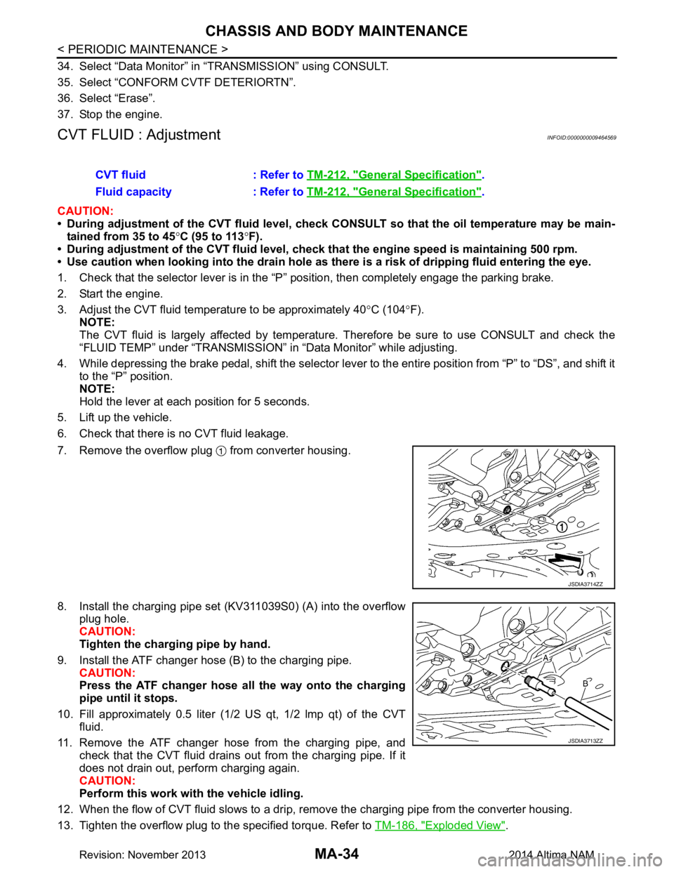
7. Remove the overflow plug from converter housing.
8. Install the charging pipe set (KV311039S0) (A) into the overflow plug hole.
CAUTION:
Tighten the charging pipe by hand.
9. Install the ATF changer hose (B) to the charging pipe. CAUTION:
Press the ATF changer hose all the way onto the charging
pipe until it stops.
10. Fill approximately 0.5 liter (1/2 US qt, 1/2 lmp qt) of the CVT
fluid.
11. Remove the ATF changer hose from the charging pipe, and check that the CVT fluid drains out from the charging pipe. If it
does not drain out, perform charging again.
CAUTION:
Perform this work with the vehicle idling.
12. When the flow of CVT fluid slows to a drip, re move the charging pipe from the converter housing.
13. Tighten the overflow plug to the specified torque. Refer to TM-186, "Exploded View"
.
CVT fluid : Refer to
TM-212, "General Specification"
.
Fluid capacity : Refer to TM-212, "General Specification"
.
JSDIA3714ZZ
JSDIA3713ZZ
Revision: November 20132014 Altima NAM
Page 3220 of 4801
MA-36
< PERIODIC MAINTENANCE >
CHASSIS AND BODY MAINTENANCE
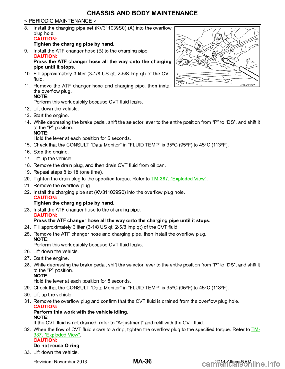
8. Install the charging pipe set (KV311039S0) (A) into the overflowplug hole.
CAUTION:
Tighten the charging pipe by hand.
9. Install the ATF changer hose (B) to the charging pipe. CAUTION:
Press the ATF changer hose all the way onto the charging
pipe until it stops.
10. Fill approximately 3 liter (3-1/8 US qt, 2-5/8 lmp qt) of the CVT
fluid.
11. Remove the ATF changer hose and charging pipe, then install the overflow plug.
NOTE:
Perform this work quickly because CVT fluid leaks.
12. Lift down the vehicle.
13. Start the engine.
14. While depressing the brake pedal, shift the selector lever to the entire position from “P” to “DS”, and shift it to the “P” position.
NOTE:
Hold the lever at each position for 5 seconds.
15. Check that the CONSULT “Data Monitor” in “FLUID TEMP” is 35 °C (95 °F) to 45 °C (113 °F).
16. Stop the engine.
17. Lift up the vehicle.
18. Remove the drain plug, and then drain CVT fluid from oil pan.
19. Repeat steps 8 to 18 (one time).
20. Tighten the drain plug to the specified torque. Refer to TM-387, "Exploded View"
.
21. Remove the overflow plug.
22. Install the charging pipe set (KV311039S0) into the overflow plug hole. CAUTION:
Tighten the charging pipe by hand.
23. Install the ATF changer hose to the charging pipe. CAUTION:
Press the ATF changer hose all the way onto the charging pipe until it stops.
24. Fill approximately 3 liter (3-1/8 US qt, 2-5/8 lmp qt) of the CVT fluid.
25. Remove the ATF changer hose and charging pipe, then install the overflow plug. NOTE:
Perform this work quickly because CVT fluid leaks.
26. Lift down the vehicle.
27. Start the engine.
28. While depressing the brake pedal, shift the selector lever to the entire position from “P” to “DS”, and shift it to the “P” position.
NOTE:
Hold the lever at each position for 5 seconds.
29. Check that the CONSULT “Data Monitor” in “FLUID TEMP” is 35 °C (95 °F) to 45 °C (113 °F).
30. Lift up the vehicle.
31. Remove the overflow plug and confirm that the CV T fluid is drained from the overflow plug hole.
CAUTION:
Perform this work with the vehicle idling.
NOTE:
If the CVT fluid is not drained, refer to “Adjustment” and refill with the CVT fluid.
32. When the flow of CVT fluid slows to a drip, tighten the overflow plug to the specified torque. Refer to TM-
387, "Exploded View".
CAUTION:
Do not reuse O-ring.
33. Lift down the vehicle.
JSDIA3713ZZ
Revision: November 20132014 Altima NAM
Page 3221 of 4801
CHASSIS AND BODY MAINTENANCEMA-37
< PERIODIC MAINTENANCE >
C
D E
F
G H
I
J
K L
M B
MA
N
O A
34. Select “Data Monitor” in “TRANSMISSION” using CONSULT.
35. Select “CONFORM CVTF DETERIORTN”.
36. Select “Erase”.
37. Stop the engine.
CVT FLUID : AdjustmentINFOID:0000000009464573
CAUTION:
• During adjustment of the CVT fluid level, check CO NSULT so that the oil temperature may be main-
tained from 35 to 45 °C (95 to 113 °F).
• During adjustment of the CVT fluid level, check that the engine speed is maintaining 500 rpm.
• Use caution when looking into the drain hole as there is a risk of dripping fluid entering the eye.
1. Check that the selector lever is in the “P ” position, then completely engage the parking brake.
2. Start the engine.
3. Adjust the CVT fluid temperature to be approximately 40 °C (104 °F).
NOTE:
The CVT fluid is largely affected by temperature. Therefore be sure to use CONSULT and check the
“FLUID TEMP” under “TRA NSMISSION” in “Data Monitor” while adjusting.
4. While depressing the brake pedal, shift the selector leve r to the entire position from “P” to “DS”, and shift it
to the “P” position.
NOTE:
Hold the lever at each position for 5 seconds.
5. Lift up the vehicle.
6. Check that there is no CVT fluid leakage.
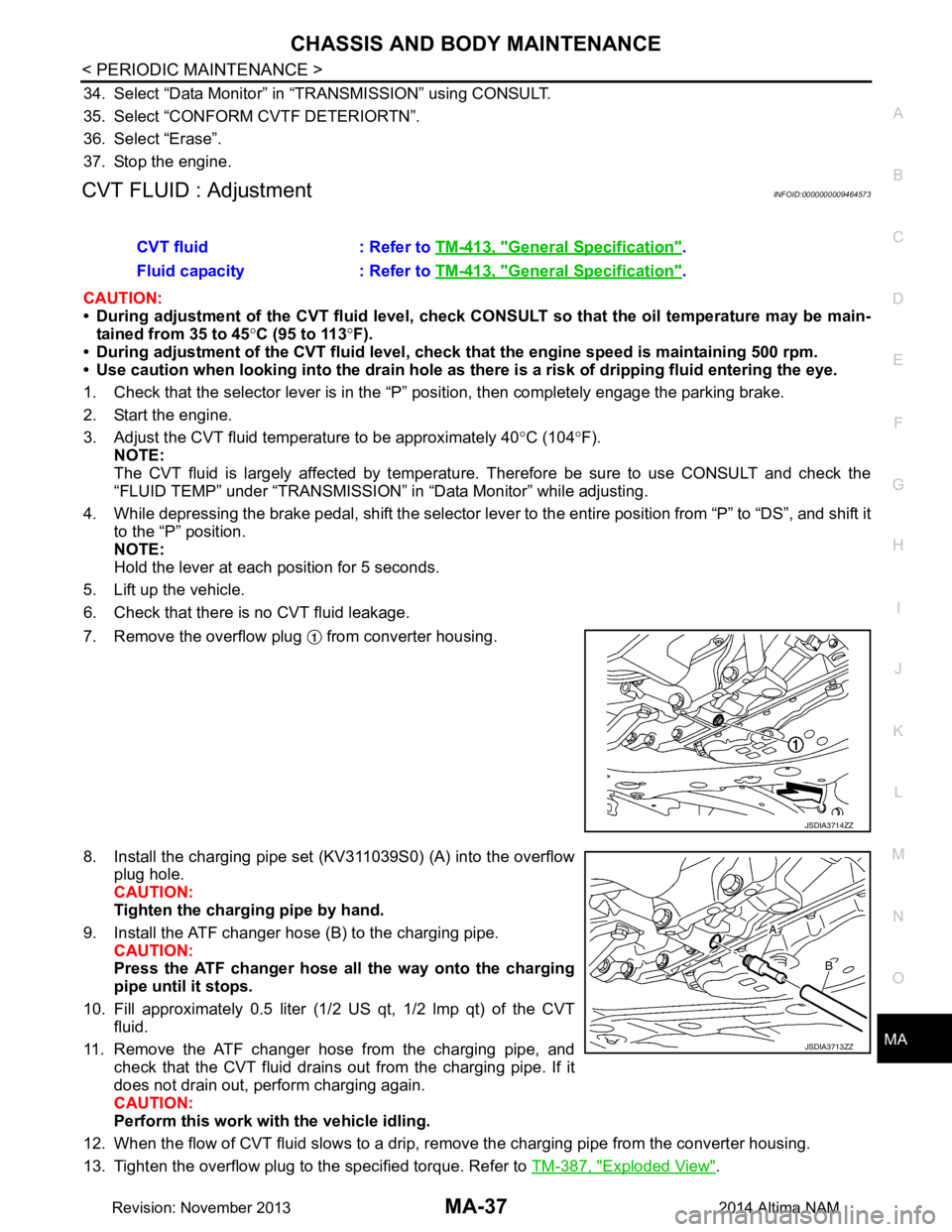
7. Remove the overflow plug from converter housing.
8. Install the charging pipe set (KV311039S0) (A) into the overflow plug hole.
CAUTION:
Tighten the charging pipe by hand.
9. Install the ATF changer hose (B) to the charging pipe. CAUTION:
Press the ATF changer hose all the way onto the charging
pipe until it stops.
10. Fill approximately 0.5 liter (1/2 US qt, 1/2 lmp qt) of the CVT
fluid.
11. Remove the ATF changer hose from the charging pipe, and check that the CVT fluid drains out from the charging pipe. If it
does not drain out, perform charging again.
CAUTION:
Perform this work with the vehicle idling.
12. When the flow of CVT fluid slows to a drip, re move the charging pipe from the converter housing.
13. Tighten the overflow plug to the specified torque. Refer to TM-387, "Exploded View"
.
CVT fluid : Refer to
TM-413, "General Specification"
.
Fluid capacity : Refer to TM-413, "General Specification"
.
JSDIA3714ZZ
JSDIA3713ZZ
Revision: November 20132014 Altima NAM
Page 3369 of 4801
![NISSAN TEANA 2014 Service Manual
PCS-20
< ECU DIAGNOSIS INFORMATION >[IPDM E/R]
IPDM E/R (INTELLIGENT POWER DI
STRIBUTION MODULE ENGINE ROOM)
IGNITION RELAY MALFUNCTION DETECTION FUNCTION
• IPDM E/R monitors the voltage at the con NISSAN TEANA 2014 Service Manual
PCS-20
< ECU DIAGNOSIS INFORMATION >[IPDM E/R]
IPDM E/R (INTELLIGENT POWER DI
STRIBUTION MODULE ENGINE ROOM)
IGNITION RELAY MALFUNCTION DETECTION FUNCTION
• IPDM E/R monitors the voltage at the con](/manual-img/5/57390/w960_57390-3368.png)
PCS-20
< ECU DIAGNOSIS INFORMATION >[IPDM E/R]
IPDM E/R (INTELLIGENT POWER DI
STRIBUTION MODULE ENGINE ROOM)
IGNITION RELAY MALFUNCTION DETECTION FUNCTION
• IPDM E/R monitors the voltage at the contact circuit and excitation coil circuit of the ignition relay inside it.
• IPDM E/R judges the ignition relay error if the voltage differs between the contact circuit and the excitation
coil circuit.
• If the ignition relay cannot turn OFF due to contact seiz ure, it activates the tail lamp relay for 10 minutes to
alert the user to the ignition relay malfunction when the ignition switch is turned OFF.
NOTE:
The tail lamp turns OFF when the ignition switch is turned ON.
FRONT WIPER CONTROL
IPDM E/R detects front wiper stop posit ion by a front wiper auto stop signal.
When a front wiper auto stop signal is in the conditions listed below, IPDM E/R stops power supply to wiper
after repeating a front wiper 10 second activation and 20 second stop five times.
NOTE:
This operation status can be confirmed on the IPDM E/ R “Data Monitor” that displays “BLOCK” for the item
“WIP PROT” while the wiper is stopped.
STARTER MOTOR PROTECTION FUNCTION
IPDM E/R turns OFF the starter control relay to protect the starter motor when the starter control relay remains
active for 90 seconds.
DTC IndexINFOID:0000000009461605
NOTE:
The details of TIME display are as follows.
• CRNT: The malfunctions that are detected now
• 1 - 39: The number is indicated when it is normal at present and a malfunction was detected in the past. It
increases like 0 → 1 → 2 ··· 38 → 39 after returning to the normal condition whenever IGN OFF → ON. It is
fixed to 39 until the self-diagnosis results are erased if it is over 39. It returns to 0 when a malfunction is
detected again in the process.
DTC Ignition switch Ignition relay Tail lamp relay
—ONON—
—OFFOFF—
B2098: IGN RELAY ON OFF ON ON (10 minutes)
B2099: IGN RELAY OFF ON OFF —
Ignition switch Front wiper switch Auto stop signal
ON OFF
Front wiper stop position signal cannot be
input 10 seconds.
ON The signal does not change for 10 seconds.
CONSULT display Fail-safe TIMENOTERefer to
No DTC is detected. Further testing may be required. — — — —
U1000: CAN COMM CIRCUIT ×CRNT 1 – 39 PCS-27
U1010: CONTROL UNIT (CAN) ×CRNT 1 – 39 PCS-28
B2098: IGN RELAY ON ×CRNT 1 – 39 PCS-29
B2099: IGN RELAY OFF — CRNT 1 – 39 PCS-30
B210B: INHIBIT relay ON stuck failure — CRNT 1 – 39 SEC-73
B210C: INHIBIT relay OFF stuck failure — CRNT 1 – 39 SEC-74
B210D: STARTER relay ON stuck failure — CRNT 1 – 39 SEC-76
B210E: STARTER relay OFF stuck failure — CRNT 1 – 39SEC-78
B210F: Interlock/NP switch ON stuck failure — CRNT 1 – 39 SEC-80
B2110: Interlock/NP switch OFF stuck failure — CRNT 1 – 39 SEC-82
Revision: November 20132014 Altima NAMRevision: November 20132014 Altima NAM
Page 4232 of 4801
![NISSAN TEANA 2014 Service Manual
COMPONENT PARTSTM-17
< SYSTEM DESCRIPTION > [CVT: RE0F10D]
C
EF
G H
I
J
K L
M A
B
TM
N
O P
• The output speed sensor generates the ON-OFF pulse (short waveform) in proportion to the rotating body NISSAN TEANA 2014 Service Manual
COMPONENT PARTSTM-17
< SYSTEM DESCRIPTION > [CVT: RE0F10D]
C
EF
G H
I
J
K L
M A
B
TM
N
O P
• The output speed sensor generates the ON-OFF pulse (short waveform) in proportion to the rotating body](/manual-img/5/57390/w960_57390-4231.png)
COMPONENT PARTSTM-17
< SYSTEM DESCRIPTION > [CVT: RE0F10D]
C
EF
G H
I
J
K L
M A
B
TM
N
O P
• The output speed sensor generates the ON-OFF pulse (short waveform) in proportion to the rotating body
speed which is “The higher the rotating body speed is, t he faster the change cycle is”. The TCM judges the
rotating speed from the changing cycle of this pulse signal.
CVT CONTROL SYSTEM : Input Speed SensorINFOID:0000000009463967
• The input speed sensor is installed to the front side of transaxle case.
• The input speed sensor detects input shaft speed.
• The input speed sensor generates an ON-OFF pulse signal according to the rotating body speed. TCM
judges the rotating body speed from the pulse signal.
CVT CONTROL SYSTEM : CVT Fluid Temperature SensorINFOID:0000000009463968
• The CVT fluid temperature sensor is installed to control valve.
• The CVT fluid temperature sensor detects CVT fluid temperature in oil pan.
JSDIA1824GB
JSDIA1824GB
Revision: November 20132014 Altima NAMRevision: November 20132014 Altima NAM
Page 4234 of 4801
![NISSAN TEANA 2014 Service Manual
COMPONENT PARTSTM-19
< SYSTEM DESCRIPTION > [CVT: RE0F10D]
C
EF
G H
I
J
K L
M A
B
TM
N
O P
• When pressure is applied to the metal diaphragm in the secondary pressure sensor, the metal diaphragm i NISSAN TEANA 2014 Service Manual
COMPONENT PARTSTM-19
< SYSTEM DESCRIPTION > [CVT: RE0F10D]
C
EF
G H
I
J
K L
M A
B
TM
N
O P
• When pressure is applied to the metal diaphragm in the secondary pressure sensor, the metal diaphragm i](/manual-img/5/57390/w960_57390-4233.png)
COMPONENT PARTSTM-19
< SYSTEM DESCRIPTION > [CVT: RE0F10D]
C
EF
G H
I
J
K L
M A
B
TM
N
O P
• When pressure is applied to the metal diaphragm in the secondary pressure sensor, the metal diaphragm is deformed, resulting in voltage change. TCM evaluates the secondary pressure from its voltage change. Volt-
age is increased along with pressure increase.
CVT CONTROL SYSTEM : Primar y Pressure Solenoid ValveINFOID:0000000009463971
• The primary pressure solenoid valve is installed to control valve.
• The primary pressure solenoid valve controls the pr imary reducing valve. For information about the primary
reducing valve, refer to TM-27, "TRANSAXLE : Component Description"
.
• The primary pressure solenoid valve uses the linear solenoid valve [N/H (normal high) type].
NOTE:
• The principle of the linear solenoid valve utilizes the fa ct that the force pressing on the valve spool installed
inside the coil increases nearly in proportion to the current . This allows it to produce a fluid pressure that is
proportional to this pressing force.
• The N/H (normal high) produces hydraulic control when the coil is not energized.
CVT CONTROL SYSTEM : Secondar y Pressure Solenoid ValveINFOID:0000000009463972
• The secondary pressure solenoid valve is installed to control valve.
• The secondary pressure solenoid valve controls the secondary reducing valve. For information about the
secondary reducing valve, refer to TM-27, "TRANSAXLE : Component Description"
.
• The secondary pressure solenoid valve uses the linear solenoid valve [N/H (normal high) type].
NOTE:
• The principle of the linear solenoid valve utilizes the fa ct that the force pressing on the valve spool installed
inside the coil increases nearly in proportion to the current . This allows it to produce a fluid pressure that is
proportional to this pressing force.
• The N/H (normal high) produces hydraulic control when the coil is not energized.
CVT CONTROL SYSTEM : Se lect Solenoid ValveINFOID:0000000009463973
• The select solenoid valve is installed to control valve.
• The select solenoid valve adjusts the tightening pressure of the forward clutch and reverse brake. For infor- mation about the forward clutch and reverse brake, refer to TM-27, "TRANSAXLE : Component Description"
.
• The select solenoid valve uses the linear solenoid valve [N/H (normal high) type].
NOTE:
• The principle of the linear solenoid valve utilizes the fa ct that the force pressing on the valve spool installed
inside the coil increases nearly in proportion to the current . This allows it to produce a fluid pressure that is
proportional to this pressing force.
• The N/H (normal high) type produces hydraulic control when the coil is not energized.
CVT CONTROL SYSTEM : Torque Converter Clutch Solenoid ValveINFOID:0000000009463974
• The torque converter clutch solenoid valve is installed to control valve.
• The torque converter clutch solenoid valve controls the torque converter clutch control valve. For information
about the torque converter clutch control valve, refer to TM-27, "TRANSAXLE : Component Description"
.
• The torque converter clutch solenoid valve utilizes a linear solenoid valve [N/L (normal low) type].
NOTE:
JSDIA1831GB
Revision: November 20132014 Altima NAMRevision: November 20132014 Altima NAM