2014 NISSAN TEANA oil change
[x] Cancel search: oil changePage 1879 of 4801
![NISSAN TEANA 2014 Service Manual
P0524 ENGINE OIL PRESSUREEC-879
< DTC/CIRCUIT DIAGNOSIS > [VQ35DE]
C
D E
F
G H
I
J
K L
M A
EC
NP
O
1. Turn ignition switch ON.
2. Select “DATA MONITOR” mode of “ENGINE” using CONSULT.
3. S NISSAN TEANA 2014 Service Manual
P0524 ENGINE OIL PRESSUREEC-879
< DTC/CIRCUIT DIAGNOSIS > [VQ35DE]
C
D E
F
G H
I
J
K L
M A
EC
NP
O
1. Turn ignition switch ON.
2. Select “DATA MONITOR” mode of “ENGINE” using CONSULT.
3. S](/manual-img/5/57390/w960_57390-1878.png)
P0524 ENGINE OIL PRESSUREEC-879
< DTC/CIRCUIT DIAGNOSIS > [VQ35DE]
C
D E
F
G H
I
J
K L
M A
EC
NP
O
1. Turn ignition switch ON.
2. Select “DATA MONITOR” mode of “ENGINE” using CONSULT.
3. Start the engine and check that “EOP SENSOR” changes, according to engine speeds.
Without CONSULT
Check engine oil pressure. Refer to LU-25, "Inspection"
.
Is the inspection result normal?
YES >> GO TO 3.
NO >> Proceed to EC-879, "Diagnosis Procedure"
.
Diagnosis ProcedureINFOID:0000000009462730
1.CHECK ENGINE OIL LEVEL
1. Turn ignition switch OFF.
2. Check engine oil level. Refer to LU-25, "Inspection"
.
Is the inspection result normal?
YES >> GO TO 2.
NO >> GO TO 4.
2.CHECK ENGINE OIL PRESSURE
With CONSULT
1. Turn ignition switch ON.
2. Select “DATA MONITOR” mode of “ENGINE” using CONSULT.
3. Start the engine and check that “EOP SENSOR” changes, according to engine speeds.
Without CONSULT
Check engine oil level. Refer to LU-25, "Inspection"
.
Is the inspection result normal?
YES >> GO TO 3.
NO >> Check oil pump. Refer to LU-29, "Removal and Installation"
.
3.CHECK EOP SENSOR
Check EOP sensor. Refer to EC-880, "Component Inspection"
.
Is the inspection result normal?
YES >> Check intermittent incident. Refer to GI-43, "Intermittent Incident".
NO >> Repair or replace error-detected parts.
4.CHECK ENGINE OIL LEAKAGE
Check engine oil leakage. Refer to LU-23, "Lubrication Circuit"
.
Is the inspection result normal?
YES >> GO TO 5.
NO >> Repair or replace error-detected parts.
Monitor item Condition Va l u e
(Approx.)
EOP SENSOR • Engine oil temperature: 80
°C (176 °F)
• Selector lever: P or N position
• Air conditioner switch: OFF
•No load Engine speed:
Idle 1,450 mV or more
Engine speed:
2,000 rpm 2,850 mV or more
Monitor item Condition Va l u e
(Approx.)
EOP SENSOR • Engine oil temperature: 80
°C (176 °F)
• Selector lever: P or N position
• Air conditioner switch: OFF
•No load Engine speed:
Idle 1,450 mV or more
Engine speed:
2,000 rpm 2,850 mV or more
Revision: November 20132014 Altima NAMRevision: November 20132014 Altima NAM
Page 2276 of 4801
EXL-10
< SYSTEM DESCRIPTION >
SYSTEM
HIGH BEAM OPERATION/FLASH-TO-PASS OPERATION
With the lighting switch in the 2nd position and placed in HIGH position, the BCM receives input requesting the
headlamp high beams to illuminate. The flash to pass f eature can be used any time and also sends a signal to
the BCM. This input is communicated to the IPDM E/R across the CAN communication lines. The CPU of the
combination meter controls the ON/OFF status off the HIGH BEAM indicator. The CPU of the IPDM E/R con-
trols the headlamp high relay coil which supplies power to the high beam headlamps.
The combination meter receives a high beam request signal (ON) through the CAN communication lines and
turns the high beam indicator lamp ON.
EXTERIOR LAMP BATTERY SAVER CONTROL
With the combination switch (lighting and turn signal switch) in the 2nd position and the ignition switch is
turned from ON or ACC to OFF, the battery saver feature is activated.
Under this condition, the headlamps remain illuminated fo r a period of time, unless the lighting switch position
is changed. If the lighting switch position is changed, then the headlamps are turned off.
AUTO LIGHT SYSTEM
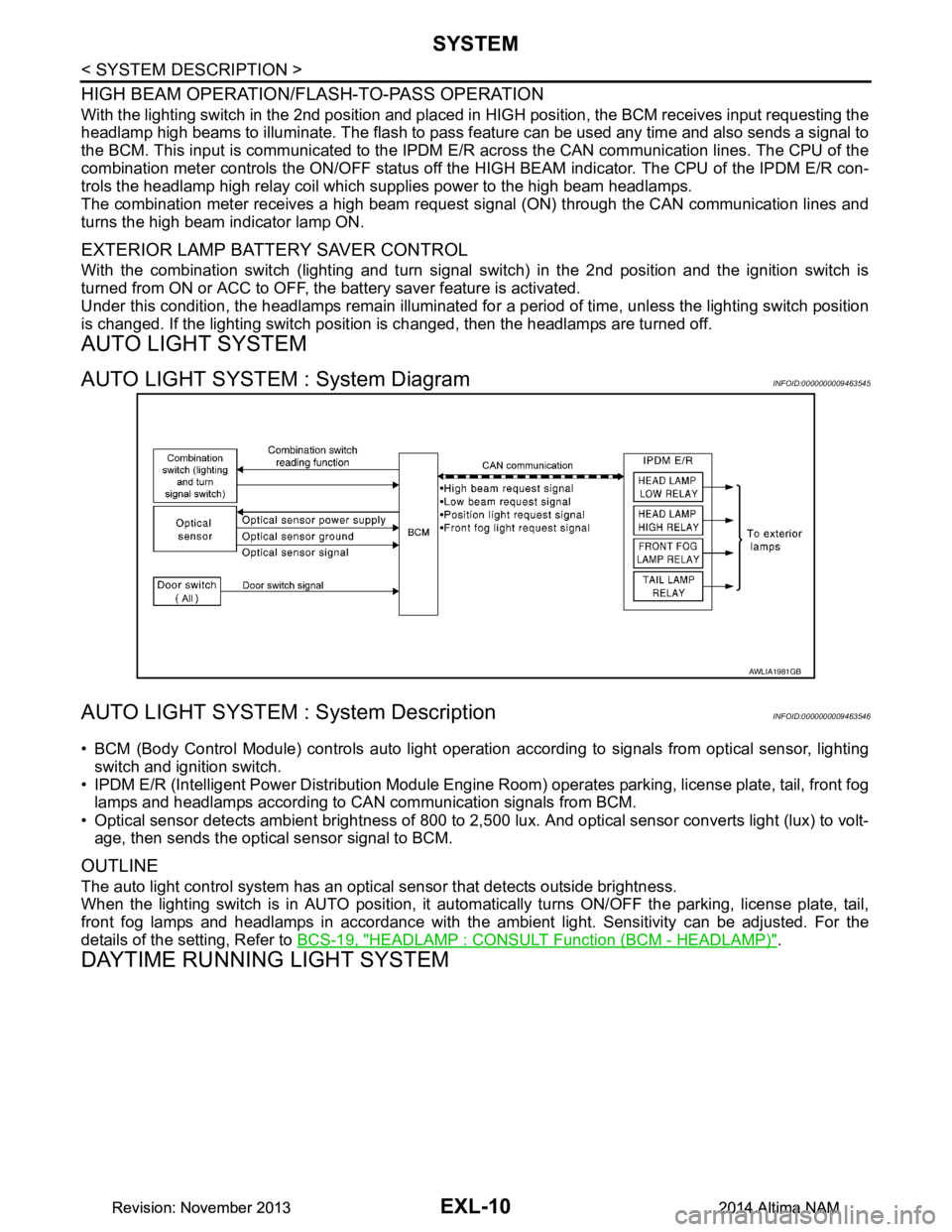
AUTO LIGHT SYSTEM : System DiagramINFOID:0000000009463545
AUTO LIGHT SYSTEM : System DescriptionINFOID:0000000009463546
• BCM (Body Control Module) controls auto light operati on according to signals from optical sensor, lighting
switch and ignition switch.
• IPDM E/R (Intelligent Power Distribution Module Engine R oom) operates parking, license plate, tail, front fog
lamps and headlamps according to CAN communication signals from BCM.
• Optical sensor detects ambient brightness of 800 to 2,500 lux. And optical sensor converts light (lux) to volt-
age, then sends the optical sensor signal to BCM.
OUTLINE
The auto light control system has an optical sensor that detects outside brightness.
When the lighting switch is in AUTO position, it autom atically turns ON/OFF the parking, license plate, tail,
front fog lamps and headlamps in accordance with the am bient light. Sensitivity can be adjusted. For the
details of the setting, Refer to BCS-19, "HEADLAMP : CONSULT Function (BCM - HEADLAMP)"
.
DAYTIME RUNNING LIGHT SYSTEM
AWLIA1981GB
Revision: November 20132014 Altima NAMRevision: November 20132014 Altima NAM
Page 2568 of 4801
GI-40
< BASIC INSPECTION >
SERVICE INFORMATION FOR ELECTRICAL INCIDENT
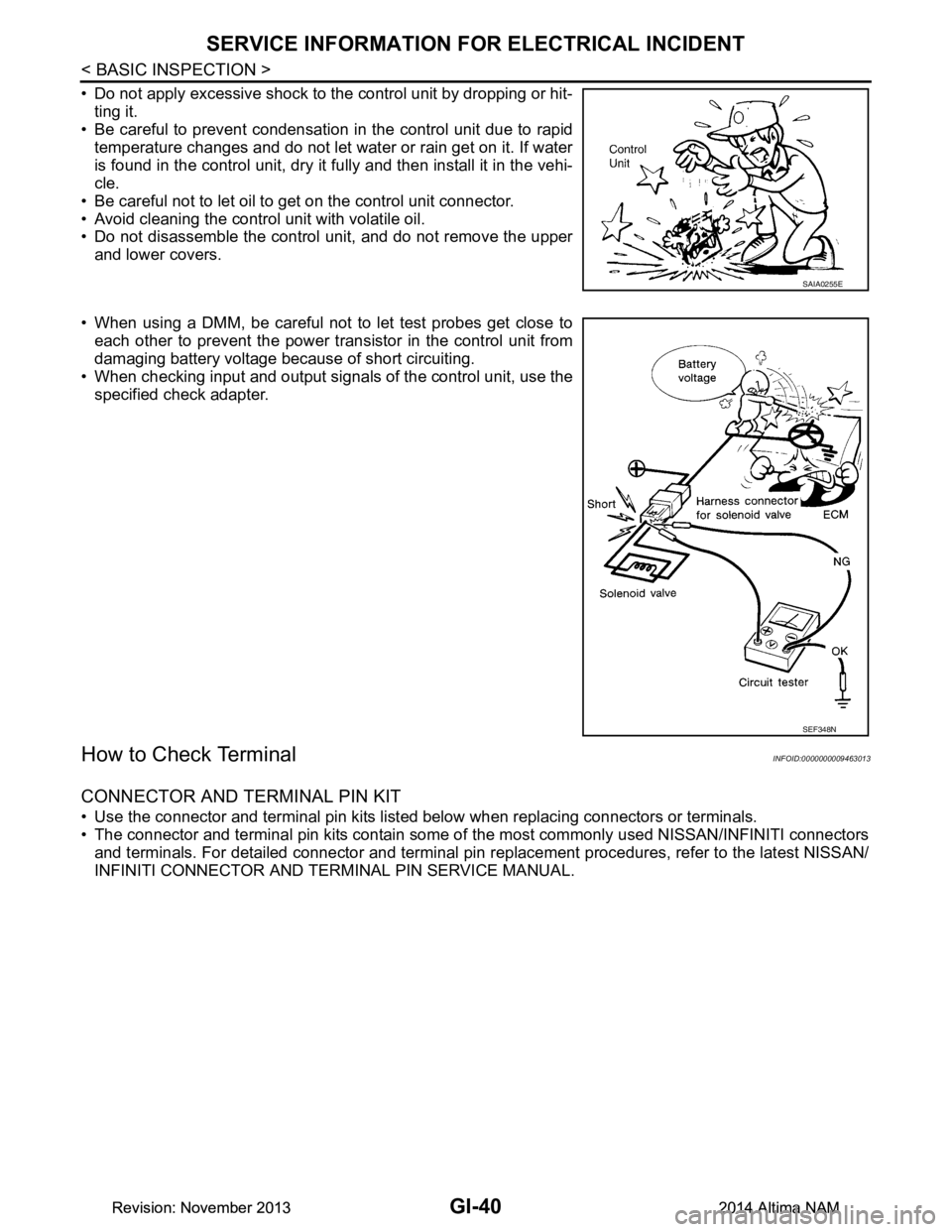
• Do not apply excessive shock to the control unit by dropping or hit-ting it.
• Be careful to prevent condensation in the control unit due to rapid
temperature changes and do not let water or rain get on it. If water
is found in the control unit, dry it fully and then install it in the vehi-
cle.
• Be careful not to let oil to get on the control unit connector.
• Avoid cleaning the control unit with volatile oil.
• Do not disassemble the control unit, and do not remove the upper
and lower covers.
• When using a DMM, be careful not to let test probes get close to each other to prevent the power tr ansistor in the control unit from
damaging battery voltage because of short circuiting.
• When checking input and output signals of the control unit, use the
specified check adapter.
How to Check TerminalINFOID:0000000009463013
CONNECTOR AND TERMINAL PIN KIT
• Use the connector and terminal pin kits listed below when replacing connectors or terminals.
• The connector and terminal pin kits contain some of the most commonly used NISSAN/INFINITI connectors
and terminals. For detailed connector and terminal pin r eplacement procedures, refer to the latest NISSAN/
INFINITI CONNECTOR AND TERMINAL PIN SERVICE MANUAL.
SAIA0255E
SEF348N
Revision: November 20132014 Altima NAMRevision: November 20132014 Altima NAM
Page 2612 of 4801
HA-6
< PRECAUTION >
PRECAUTIONS
The new and former refrigerant connections use different O-ring configurations. Do not confuse O-
rings since they are not interchangeable. If a wrong O-ring is installed, refrigerant will leak at, or
around, the connection.
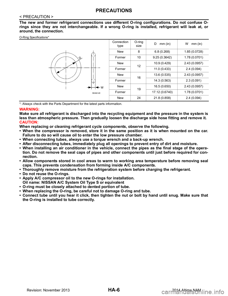
O-Ring Specifications*
*: Always check with the Parts Department for the latest parts information.
WARNING:
Make sure all refrigerant is discharged into the recycling equipment and the pressure in the system is
less than atmospheric pressure. Then gradually loo sen the discharge side hose fitting and remove it.
CAUTION:
When replacing or cleaning refrigeran t cycle components, observe the following.
• When the compressor is removed, store it in the same position as it is when mounted on the car.
Failure to do so will cause oil to enter the low pressure chamber.
• When connecting tubes, always use a torque wrench and a back-up wrench.
• After disconnecting tubes, immedi ately plug all openings to prevent entry of dirt and moisture.
• When installing an air conditioner in the vehicle, connect the pipes as the final stage of the opera-
tion. Do not remove the seal caps of pipes and othe r components until just before required for con-
nection.
• Allow components stored in cool areas to warm to working area temperature before removing seal
caps. This prevents condensation from forming inside A/C components.
• Thoroughly remove moisture from the refrigerat ion system before charging the refrigerant.
• Do not reuse the O-rings.
• Apply A/C compressor oil to th e new O-rings for installation.
Oil name: NISSAN A/C System Oil Type S or equivalent
• O-ring must be closely attached to dented portion of tube.
• When replacing the O-ring, be careful not to damage O-ring and tube.
• Connect tube until you hear it cl ick, then tighten the nut or bolt by hand until snug. Make sure that
the O-ring is installed to tube correctly.
Connection
type O-ring
size D mm (in) W mm (in)
New 8 6.8 (0.268) 1.85 (0.0728)
Former 10 9.25 (0.3642) 1.78 (0.0701) New 1210.9 (0.429) 2.43 (0.0957)
Former 11.0 (0.433) 2.4 (0.094) New 1613.6 (0.535) 2.43 (0.0957)
Former 14.3 (0.563) 2.3 (0.091) New 1916.5 (0.650) 2.43 (0.0957)
Former 17.12 (0.6740) 1.78 (0.0701) New 24 21.8 (0.858) 2.4 (0.094)
SHA814E
Revision: November 20132014 Altima NAM
Page 2615 of 4801
PREPARATIONHA-9
< PREPARATION >
C
D E
F
G H
J
K L
M A
B
HA
N
O P
PREPARATION
PREPARATION
Special Service ToolINFOID:0000000009463915
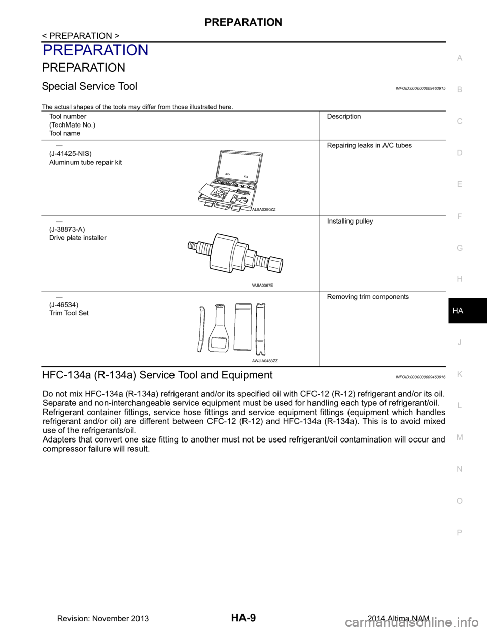
The actual shapes of the tools may differ from those illustrated here.
HFC-134a (R-134a) Servic e Tool and EquipmentINFOID:0000000009463916
Do not mix HFC-134a (R-134a) refrigerant and/or its specif ied oil with CFC-12 (R-12) refrigerant and/or its oil.
Separate and non-interchangeable service equipment must be used for handling each type of refrigerant/oil.
Refrigerant container fittings, service hose fittings and service equipment fittings (equipment which handles
refrigerant and/or oil) are different between CFC-12 (R-12) and HFC-134a (R-134a). This is to avoid mixed
use of the refrigerants/oil.
Adapters that convert one size fitting to another must not be used refrigerant/oil contamination will occur and
compressor failure will result.
Tool number
(TechMate No.)
Tool name Description
—
(J-41425-NIS)
Aluminum tube repair kit Repairing leaks in A/C tubes
—
(J-38873-A)
Drive plate installer Installing pulley
—
(J-46534)
Trim Tool Set Removing trim components
ALIIA0390ZZ
WJIA0367E
AWJIA0483ZZ
Revision: November 20132014 Altima NAM
Page 2631 of 4801
OIL
HA-25
< PERIODIC MAINTENANCE >
C
D E
F
G H
J
K L
M A
B
HA
N
O P
OIL
DescriptionINFOID:0000000009463930
MAINTENANCE OF OIL LEVEL
The compressor oil is circulating in the system together wi th the refrigerant. It is necessary to fill compressor
with oil when replacing A/C system parts or when a large amount of refrigerant leakage is detected. It is impor-
tant to always maintain oil level within the spec ified level, otherwise the following conditions may occur:
• Insufficient oil amount: Stuck compressor
• Excessive oil amount: Insufficient coo ling (caused by insufficient heat exchange)
InspectionINFOID:0000000009463931
If a compressor is malfunctioning (internal noise, insufficient cooling), check the compressor oil.
1.COMPRESSOR OIL JUDGMENT
1. Remove the compressor. Refer to HA-30, "COMPRESSOR : Removal and Installation"
.
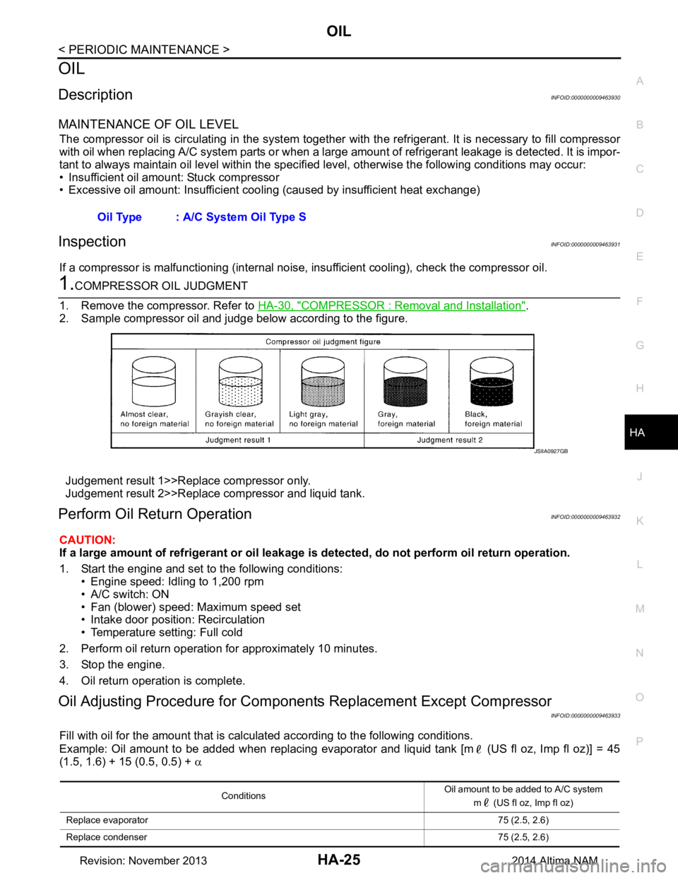
2. Sample compressor oil and judge below according to the figure.
Judgement result 1>>Replace compressor only.
Judgement result 2>>Replace compressor and liquid tank.
Perform Oil Return OperationINFOID:0000000009463932
CAUTION:
If a large amount of refrigerant or oil leakage is detected, do not perform oil return operation.
1. Start the engine and set to the following conditions: • Engine speed: Idling to 1,200 rpm
• A/C switch: ON
• Fan (blower) speed: Maximum speed set
• Intake door position: Recirculation
• Temperature setting: Full cold
2. Perform oil return operation for approximately 10 minutes.
3. Stop the engine.
4. Oil return operation is complete.
Oil Adjusting Procedure for Component s Replacement Except Compressor
INFOID:0000000009463933
Fill with oil for the amount that is calculated according to the following conditions.
Example: Oil amount to be added when replacing evaporator and liquid tank [m (US fl oz, Imp fl oz)] = 45
(1.5, 1.6) + 15 (0.5, 0.5) + α
Oil Type : A/C System Oil Type S
JSIIA0927GB
Conditions
Oil amount to be added to A/C system
m (US fl oz, Imp fl oz)
Replace evaporator 75 (2.5, 2.6)
Replace condenser 75 (2.5, 2.6)
Revision: November 20132014 Altima NAM
Page 3168 of 4801
![NISSAN TEANA 2014 Service Manual
LU-18
< SERVICE DATA AND SPECIFICATIONS (SDS) [QR25DE]
SERVICE DATA AND SPECIFICATIONS (SDS)
SERVICE DATA AND SPECIFICATIONS (SDS)
SERVICE DATA AND SPECIFICATIONS (SDS)
Oil PressureINFOID:00000000094 NISSAN TEANA 2014 Service Manual
LU-18
< SERVICE DATA AND SPECIFICATIONS (SDS) [QR25DE]
SERVICE DATA AND SPECIFICATIONS (SDS)
SERVICE DATA AND SPECIFICATIONS (SDS)
SERVICE DATA AND SPECIFICATIONS (SDS)
Oil PressureINFOID:00000000094](/manual-img/5/57390/w960_57390-3167.png)
LU-18
< SERVICE DATA AND SPECIFICATIONS (SDS) [QR25DE]
SERVICE DATA AND SPECIFICATIONS (SDS)
SERVICE DATA AND SPECIFICATIONS (SDS)
SERVICE DATA AND SPECIFICATIONS (SDS)
Oil PressureINFOID:0000000009461038
Unit: kPa (kg/cm2, psi)
*: Engine oil temperature at 80
°C (176 °F)
Oil PumpINFOID:0000000009461039
Unit: mm (in)
Regulator ValveINFOID:0000000009461040
Unit: mm (in)
Oil CapacityINFOID:0000000009461041
Unit: (US qt, Imp qt)
Engine speed Approximate discharge oil pressure*
Idle speed 98 (1.0, 14)
2,000 rpm 294 (3.0, 43)
6,000 rpm 392 (4.0, 57)
Clearance between outer rotor and oil pump body 0.114 - 0.179 (0.0045 - 0.0070)
Tip clearance between inner rotor and outer rotor 0.170 - 0.220 (0.0067 - 0.0087)
Side clearance between inner rotor and oil pump body 0.030 - 0.070 (0.0012 - 0.0028)
Side clearance between outer rotor and oil pump body 0.060 - 0.110 (0.0024 - 0.0043)
Inner rotor to brazed portion of housing clearance 0.035 - 0.070 (0.0014 - 0.0028)
Regulator valve to oil pump cover clearance 0.040 - 0.097 (0.0016 - 0.0038)
Drain and refill With oil filter change Approximately 4.6 (4-7/8, 4)
Without oil filter change Approximately 4.3 (4-1/2, 3-3/4)
Dry engine (engine overhaul) Approximately 5.4 (5-3/4, 4-3/4)
Revision: November 20132014 Altima NAM
Page 3184 of 4801
![NISSAN TEANA 2014 Service Manual
LU-34
< SERVICE DATA AND SPECIFICATIONS (SDS) [VQ35DE]
SERVICE DATA AND SPECIFICATIONS (SDS)
SERVICE DATA AND SPECIFICATIONS (SDS)
SERVICE DATA AND SPECIFICATIONS (SDS)
Oil PressureINFOID:00000000094 NISSAN TEANA 2014 Service Manual
LU-34
< SERVICE DATA AND SPECIFICATIONS (SDS) [VQ35DE]
SERVICE DATA AND SPECIFICATIONS (SDS)
SERVICE DATA AND SPECIFICATIONS (SDS)
SERVICE DATA AND SPECIFICATIONS (SDS)
Oil PressureINFOID:00000000094](/manual-img/5/57390/w960_57390-3183.png)
LU-34
< SERVICE DATA AND SPECIFICATIONS (SDS) [VQ35DE]
SERVICE DATA AND SPECIFICATIONS (SDS)
SERVICE DATA AND SPECIFICATIONS (SDS)
SERVICE DATA AND SPECIFICATIONS (SDS)
Oil PressureINFOID:0000000009461057
Unit: kPa (kg/cm2, psi)
*: Engine oil temperature at 80
°C (176 °F)
Oil PumpINFOID:0000000009461058
Unit: mm (in)
Regulator ValveINFOID:0000000009461059
Unit: mm (in)
Oil CapacityINFOID:0000000009461060
Unit: (US qt, Imp qt)
Engine speed Approximate discharge oil pressure*
Idle speed 98 (1.0, 14)
2,000 rpm 294 (3.0, 43)
6,000 rpm 392 (4.0, 57)
Clearance between outer rotor and oil pump body 0.114 - 0.260 (0.0045 - 0.0102)
Tip clearance between inner rotor and outer rotor Below 0.180 (0.0071)
Side clearance between inner rotor and oil pump body 0.030 - 0.070 (0.0012 - 0.0028)
Side clearance between outer rotor and oil pump body 0.050 - 0.110 (0.0020 - 0.0043)
Clearance between inner rotor and oil pump body 0.045 - 0.091 (0.0018 - 0.0036)
Regulator valve to oil pump cover clearance 0.040 - 0.097 (0.0016 - 0.0038)
Drain and refill With oil filter change 4.8 (5-1/8, 4-1/4)
Without oil filter change 4.5 (4-3/4, 4)
Dry engine (engine overhaul) 5.3 (5-5/8, 4-5/8)
Revision: November 20132014 Altima NAM