2014 NISSAN TEANA length
[x] Cancel search: lengthPage 2475 of 4801
FRONT DRIVE SHAFTFAX-23
< UNIT DISASSEMBLY AND ASSEMBLY >
CEF
G H
I
J
K L
M A
B
FA X
N
O P
• Check damper for cracks or wear. Install damper with new damper bands.
ASSEMBLY
Transaxle Side
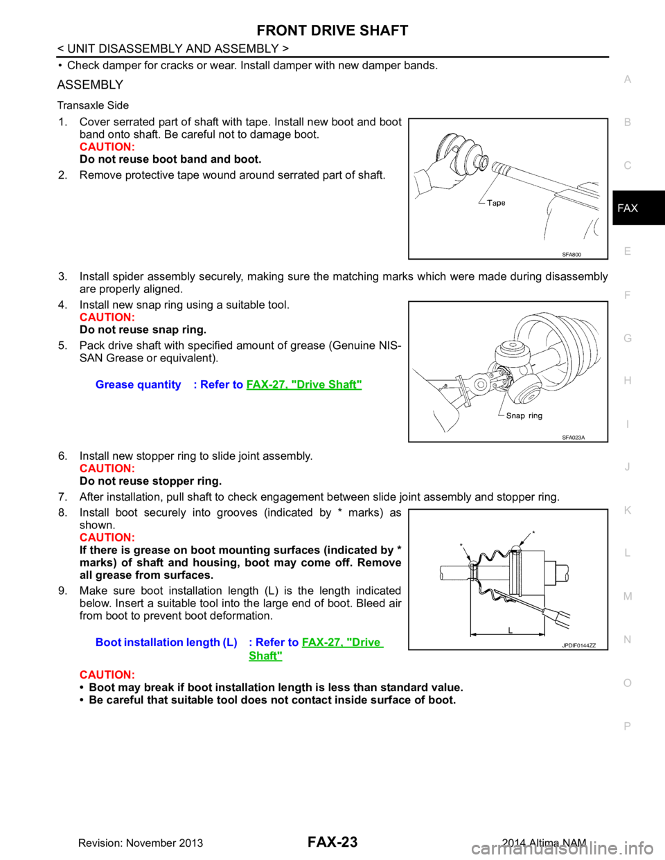
1. Cover serrated part of shaft with tape. Install new boot and boot band onto shaft. Be careful not to damage boot.
CAUTION:
Do not reuse boot band and boot.
2. Remove protective tape wound around serrated part of shaft.
3. Install spider assembly securely, making sure the matching marks which were made during disassembly are properly aligned.
4. Install new snap ring using a suitable tool. CAUTION:
Do not reuse snap ring.
5. Pack drive shaft with specifi ed amount of grease (Genuine NIS-
SAN Grease or equivalent).
6. Install new stopper ring to slide joint assembly. CAUTION:
Do not reuse stopper ring.
7. After installation, pull shaft to check engagement between slide joint assembly and stopper ring.
8. Install boot securely into grooves (indicated by * marks) as shown.
CAUTION:
If there is grease on boot mounting surfaces (indicated by *
marks) of shaft and housing, boot may come off. Remove
all grease from surfaces.
9. Make sure boot installation length (L) is the length indicated below. Insert a suitable tool into the large end of boot. Bleed air
from boot to prevent boot deformation.
CAUTION:
• Boot may break if boot installation le ngth is less than standard value.
• Be careful that suitable tool does not contact inside surface of boot.
SFA800
Grease quantity : Refer to FAX-27, "Drive Shaft"
SFA023A
Boot installation length (L) : Refer to FAX-27, "Drive
Shaft"
JPDIF0144ZZ
Revision: November 20132014 Altima NAM
Page 2477 of 4801
FRONT DRIVE SHAFTFAX-25
< UNIT DISASSEMBLY AND ASSEMBLY >
CEF
G H
I
J
K L
M A
B
FA X
N
O P
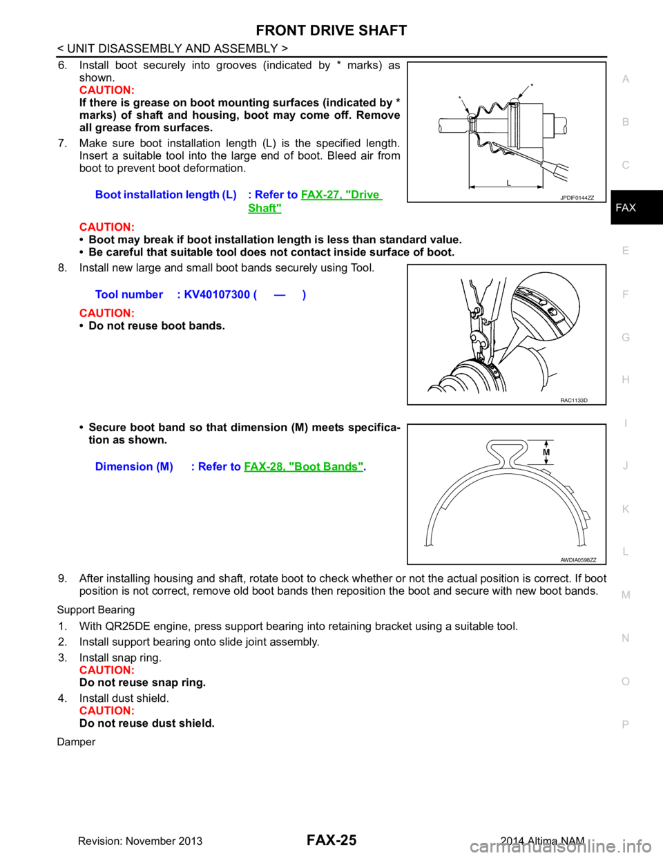
6. Install boot securely into grooves (indicated by * marks) as shown.
CAUTION:
If there is grease on boot mounting surfaces (indicated by *
marks) of shaft and housing, boot may come off. Remove
all grease from surfaces.
7. Make sure boot installation length (L) is the specified length. Insert a suitable tool into the large end of boot. Bleed air from
boot to prevent boot deformation.
CAUTION:
• Boot may break if boot installation le ngth is less than standard value.
• Be careful that suitable tool does not contact inside surface of boot.
8. Install new large and small boot bands securely using Tool.
CAUTION:
• Do not reuse boot bands.
• Secure boot band so that dimension (M) meets specifica- tion as shown.
9. After installing housing and shaft, rotate boot to check whether or not the actual position is correct. If boot
position is not correct, remove old boot bands t hen reposition the boot and secure with new boot bands.
Support Bearing
1. With QR25DE engine, press support bearing into retaining bracket using a suitable tool.
2. Install support bearing onto slide joint assembly.
3. Install snap ring. CAUTION:
Do not reuse snap ring.
4. Install dust shield. CAUTION:
Do not reuse dust shield.
Damper
Boot installation length (L) : Refer to FAX-27, "Drive
Shaft"
Tool number : KV40107300 ( — )
JPDIF0144ZZ
RAC1133D
Dimension (M) : Refer to FAX-28, "Boot Bands".
AWDIA0598ZZ
Revision: November 20132014 Altima NAM
Page 2479 of 4801
SERVICE DATA AND SPECIFICATIONS (SDS)FAX-27
< SERVICE DATA AND SPECIFICATIONS (SDS)
CEF
G H
I
J
K L
M A
B
FA X
N
O P
SERVICE DATA AND SPECIFICATIONS (SDS)
SERVICE DATA AND SPECIFICATIONS (SDS)
Wheel BearingINFOID:0000000009464446
Drive ShaftINFOID:0000000009464447
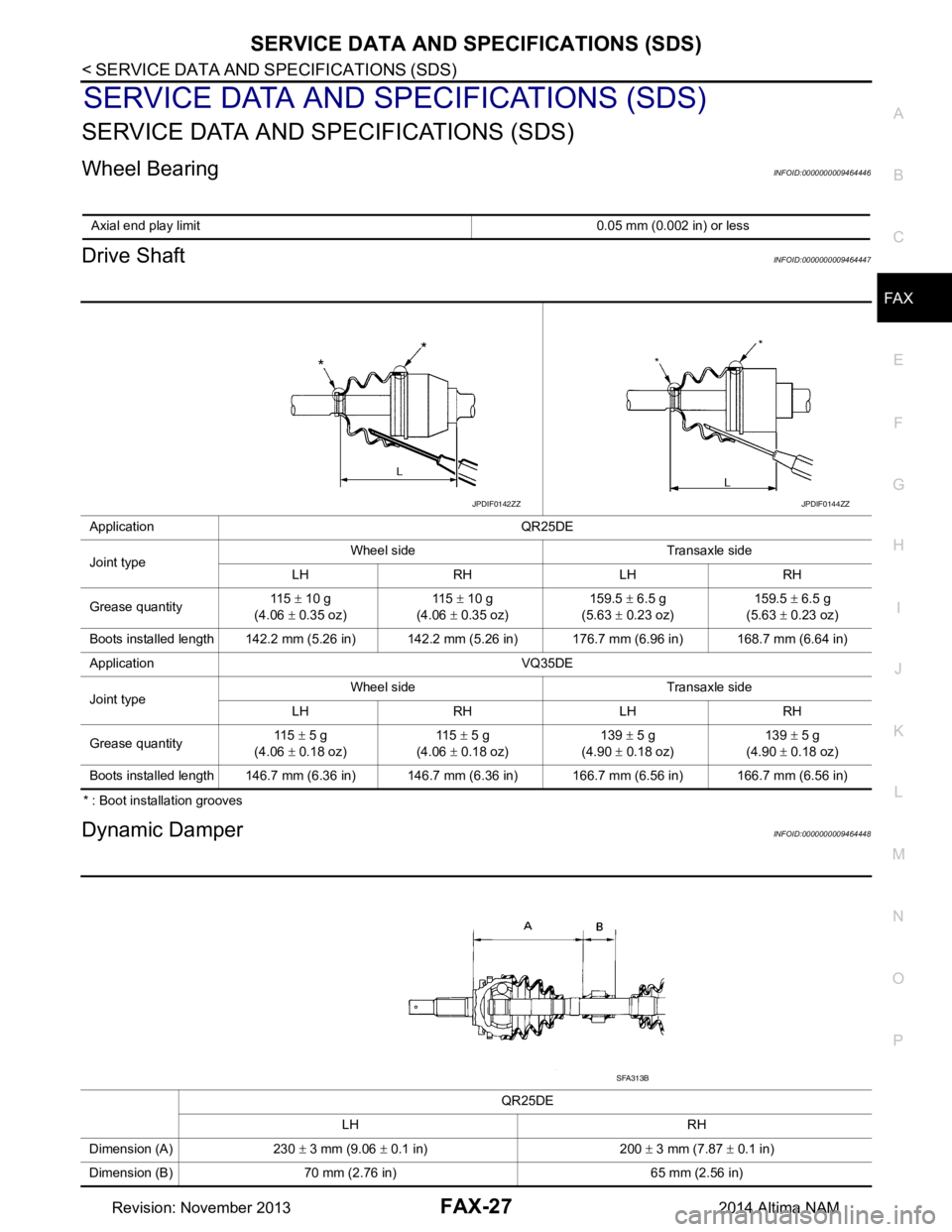
* : Boot installation grooves
Dynamic DamperINFOID:0000000009464448
Axial end play limit 0.05 mm (0.002 in) or less
Application QR25DE
Joint type Wheel side Transaxle side
LH RH LH RH
Grease quantity 11 5
± 10 g
(4.06 ± 0.35 oz) 11 5
± 10 g
(4.06 ± 0.35 oz) 159.5
± 6.5 g
(5.63 ± 0.23 oz) 159.5
± 6.5 g
(5.63 ± 0.23 oz)
Boots installed length 142.2 mm (5.26 in) 142.2 mm (5.26 in) 176.7 mm (6.96 in) 168.7 mm (6.64 in)
Application VQ35DE
Joint type Wheel side Transaxle side
LH RH LH RH
Grease quantity 115
± 5 g
(4.06 ± 0.18 oz) 11 5
± 5 g
(4.06 ± 0.18 oz) 139
± 5 g
(4.90 ± 0.18 oz) 139
± 5 g
(4.90 ± 0.18 oz)
Boots installed length 146.7 mm (6.36 in) 146.7 mm (6.36 in) 166.7 mm (6.56 in) 166.7 mm (6.56 in)
JPDIF0142ZZJPDIF0144ZZ
QR25DE
LH RH
Dimension (A) 230 ± 3 mm (9.06 ± 0.1 in) 200 ± 3 mm (7.87 ± 0.1 in)
Dimension (B) 70 mm (2.76 in) 65 mm (2.56 in)
SFA313B
Revision: November 20132014 Altima NAM
Page 2553 of 4801
IDENTIFICATION INFORMATIONGI-25
< VEHICLE INFORMATION >
C
D E
F
G H
I
J
K L
M B
GI
N
O P
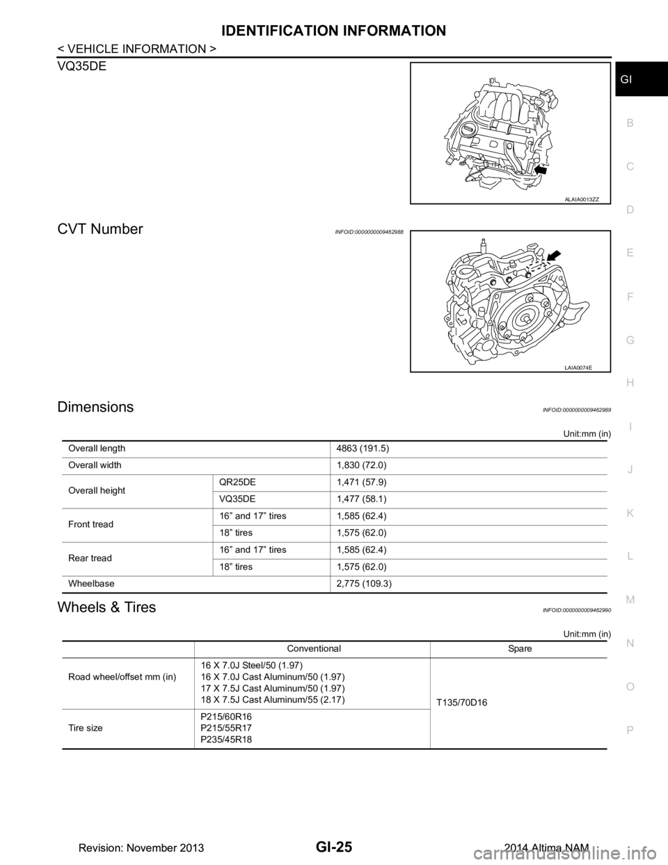
VQ35DE
CVT NumberINFOID:0000000009462988
DimensionsINFOID:0000000009462989
Unit:mm (in)
Wheels & TiresINFOID:0000000009462990
Unit:mm (in)
ALAIA0013ZZ
LAIA0074E
Overall length 4863 (191.5)
Overall width 1,830 (72.0)
Overall height QR25DE 1,471 (57.9)
VQ35DE 1,477 (58.1)
Front tread 16” and 17” tires 1,585 (62.4)
18” tires 1,575 (62.0)
Rear tread 16” and 17” tires 1,585 (62.4)
18” tires 1,575 (62.0)
Wheelbase 2,775 (109.3)
Conventional Spare
Road wheel/offset mm (in) 16 X 7.0J Steel/50 (1.97)
16 X 7.0J Cast Aluminum/50 (1.97)
17 X 7.5J Cast Aluminum/50 (1.97)
18 X 7.5J Cast Aluminum/55 (2.17) T135/70D16
Tire size P215/60R16
P215/55R17
P235/45R18
Revision: November 20132014 Altima NAMRevision: November 20132014 Altima NAM
Page 2558 of 4801
GI-30
< PRECAUTION >
PRECAUTIONS
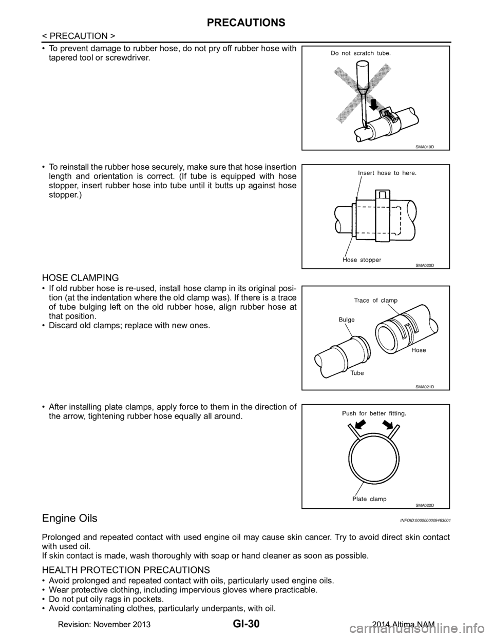
• To prevent damage to rubber hose, do not pry off rubber hose withtapered tool or screwdriver.
• To reinstall the rubber hose securely, make sure that hose insertion length and orientation is correct. (If tube is equipped with hose
stopper, insert rubber hose into tube until it butts up against hose
stopper.)
HOSE CLAMPING
• If old rubber hose is re-used, install hose clamp in its original posi- tion (at the indentation where the old clamp was). If there is a trace
of tube bulging left on the old rubber hose, align rubber hose at
that position.
• Discard old clamps; replace with new ones.
• After installing plate clamps, apply force to them in the direction of the arrow, tightening rubber hose equally all around.
Engine OilsINFOID:0000000009463001
Prolonged and repeated contact with used engine oil may cause skin cancer. Try to avoid direct skin contact
with used oil.
If skin contact is made, wash thoroughly with soap or hand cleaner as soon as possible.
HEALTH PROTECTION PRECAUTIONS
• Avoid prolonged and repeated contact with oils, particularly used engine oils.
• Wear protective clothing, including impervious gloves where practicable.
• Do not put oily rags in pockets.
• Avoid contaminating clothes, pa rticularly underpants, with oil.
SMA019D
SMA020D
SMA021D
SMA022D
Revision: November 20132014 Altima NAMRevision: November 20132014 Altima NAM
Page 3740 of 4801
COMPONENT INSPECTIONSB-5
< BASIC INSPECTION >
C
D E
F
G
I
J
K L
M A
B
SB
N
O P
BASIC INSPECTION
COMPONENT INSPECTION
InspectionINFOID:0000000009462960
AFTER A COLLISION
WARNING:
Inspect all seat belt assemblies in cluding retractors and attaching hardware after any collision.
NISSAN/INFINITI recommends that all seat belt assemblies in use during a collision be replaced
unless the collision was minor and th e belts show no damage and continue to operate properly. Fail-
ure to do so could result in serious personal inju ry in an accident. Seat belt assemblies not in use dur-
ing a collision should also be replaced if either da mage or improper operation is noted. Seat belt pre-
tensioners should be replaced even if the seat belts are not in use during a frontal collision in which
the air bags are deployed.
Replace any seat belt assembly (including anchor bolts) if:
• The seat belt was in use at the time of a collision (except for minor collisions and the belts, retractors and
buckles show no damage and continue to operate properly).
• The seat belt was damaged in an accident (i.e. torn webbing, bent retractor or guide, etc.).
• The seat belt attaching point is damaged in an accident . Inspect the seat belt attaching area for damage or
distortion and repair if necessary before installing a new seat belt assembly.
• Anchor bolts are deformed or worn out.
• The seat belt pre-tensioner should be replaced even if t he seat belts are not in use during the collision in
which the air bags are deployed.
PRELIMINARY CHECKS
1. Check the seat belt warning lamp for proper operation per the following:
a. Turn ignition switch ON. The seat belt warning lamp should illuminate.
b. Fasten driver seat belt. The seat belt warning lamp should turn OFF.
2. If the air bag warning lamp is blinking, perform self-diagnosis with CONSULT and air bag warning lamp. Refer to SRC-17, "Trouble Diagnosis without CONSULT"
.
3. Check that the seat belt retractor, seat belt anchor and buckle bolts are tightened firmly.
4. Check the shoulder seat belt guide and shoulder belt height adjuster for front seats. Check that guide
swivels freely and that webbing lays flat and does not bind in guide. Check that height adjuster operates
properly and holds securely.
5. Check retractor operation:
a. Fully extend the seat belt webbing and check for twists, tears or other damage.
b. Allow the seat belt to retract. Check that webbing retu rns smoothly and completely into the retractor. If the
seat belt does not return smoothly, wipe the inside of t he loops with a clean paper cloth. Dirt build-up in the
loops of the upper anchors can cause t he seat belts to retract slowly.
c. Fasten the seat belt. Check that seat belt returns sm oothly and completely to the retractor. If the webbing
does not return smoothly, the cause may be an accu mulation of dust or dirt. Use the “SEAT BELT TAPE
SET” and perform the following steps.
d. Inspect the front seat belt D-ring anchor 1. Pull the seat belt out to a length of 500 mm (19.69 in) or more.
2. Hold the seat belt at the center pillar webbing opening with a clip or other device.
3. Pass a thin wire through the D-ring anchor webbing opening. Hold both ends of the wire and pull it tightly while moving it up and down several times along the webbing opening surface to remove dirt
stuck there.
4. Any dirt that cannot be removed with the wire can be removed by cleaning the opening with a clean
cloth.
5. Apply tape at the point where the webbing contacts the D-ring anchor webbing opening. NOTE:
Apply the tape so that there is no slack or wrinkling.
6. Remove the clip holding the seat belt and check that the webbing returns smoothly.
6. Repeat steps above if necessary to check the other seat belts.
Revision: November 20132014 Altima NAM
Page 3741 of 4801
SB-6
< BASIC INSPECTION >
COMPONENT INSPECTION
SEAT BELT RETRACTOR ON-VEHICLE CHECK
Emergency Locking Retractors (ELR) and Automatic Locking Retractors (ALR)
NOTE:
All seat belt retractors are Emergency Locking Retr actors (ELR) type. In an emergency (sudden stop) the
retractor will lock and prevent the webbing from extendi ng any further. All 3-point type seat belt retractors
except the driver seat belt also have an Automati c Locking Retractors (ALR) mode. The ALR mode (also
called child restraint mode) is used when installing child seats. The ALR mode is activated when the seat belt
is fully extended. When the webbing is then retracted part ially, the ALR mode automatically locks the seat belt
in a specific position so the webbing cannot be extended any further. To cancel the ALR mode, allow the seat
belt to fully wind back into the retractor.
Check the seat belt retractors with the following test(s ) to determine if a retractor assembly is operating prop-
erly.
ELR Function Stationary Check
Grasp the shoulder webbing and pull forward quickly. T he retractor should lock and prevent the belt from
extending further.
ALR Function Stationary Check
1. Pull out the entire length of seat belt from retractor until a click is heard.
2. Retract the webbing partially. A clicking noise shoul d be heard as the webbing retracts, indicating that the
retractor is in the Automatic Locking Retractors (ALR) mode.
3. Grasp the seat belt and try to pull out the retractor. The webbing must lock and not extend any further. If it
does not operate normally, replace the retractor assembly.
4. Allow the entire length of the webbing to re tract to cancel the automatic locking mode.
ELR Function Moving Check
WARNING:
Perform the following test in a saf e, open area clear of other vehicles and obstructions (for example, a
large, empty parking lot). Road surface must be p aved and dry. Never perform the following test on
wet or gravel roads or on public streets and highw ays. This could result in an accident and serious
personal injury. The driver and passenger must be prepared to brace themselves in the event that the
retractor does not lock.
1. Fasten driver seat belt. Buckle a passenger in to the seat for the belt that is to be tested.
2. Proceed to the designated safe area.
3. Drive the vehicle at approximately 16 km/h ( 10 MPH). Notify any passengers of a pending sudden stop
and the driver and passenger must be prepared to brace themselves in the event that the retractor does
not lock. Apply brakes firmly and make a very hard stop.
During stopping, seat belts should lock and not be extended. If the seat belt retractor assembly does not lock,
perform the retractor off-vehicle check.
SEAT BELT RETRACTOR O FF-VEHICLE CHECK (PILLAR)
1. Remove the seat belt retractor.
• Remove the front seat belt assembly, refer to SB-8, "Removal and Installation"
.
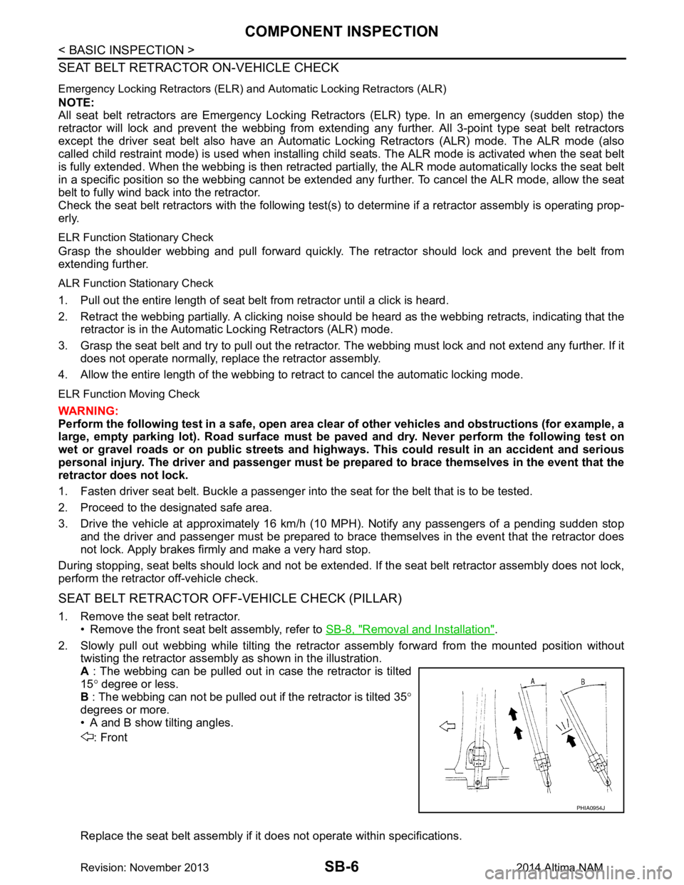
2. Slowly pull out webbing while tilting the retracto r assembly forward from the mounted position without
twisting the retractor assembly as shown in the illustration.
A : The webbing can be pulled out in case the retractor is tilted
15 ° degree or less.
B : The webbing can not be pulled out if the retractor is tilted 35 °
degrees or more.
• A and B show tilting angles.
: Front
Replace the seat belt assembly if it does not operate within specifications.
PHIA0954J
Revision: November 20132014 Altima NAM
Page 4016 of 4801
DIAGNOSIS SENSOR UNITSRC-23
< ECU DIAGNOSIS INFORMATION >
C
D E
F
G
I
J
K L
M A
B
SRC
N
O P
Flash Code IndexINFOID:0000000009460732
WARNING LAMP FLASH CODE CHART
How to read flash codes
1. Put the vehicle in Diagnosis Mode. Refer to SRC-17, "Trouble Diagnosis without CONSULT".
2. All codes are proceded by a seven second "holding" flash.
3. Identify how many primary flashes are display ed as well as the length of each primary flash.
4. Refer to the tables and examples below to determine which SRS subsystem the code belongs to.
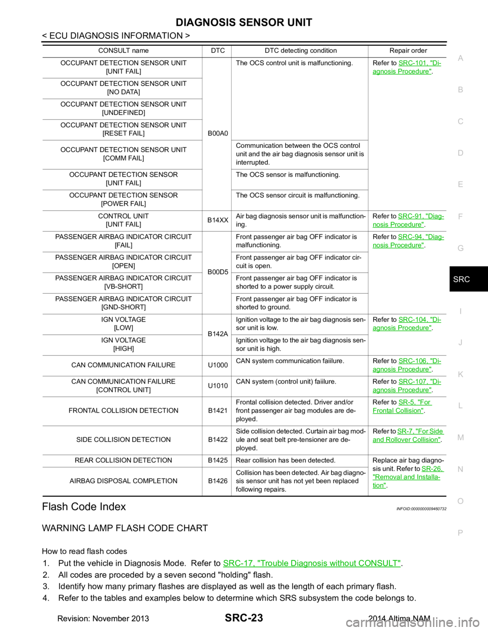
OCCUPANT DETECTION SENSOR UNIT [UNIT FAIL]
B00A0The OCS control unit is malfunctioning. Refer to
SRC-101, "Di-
agnosis Procedure".
OCCUPANT DETECTION SENSOR UNIT [NO DATA]
OCCUPANT DETECTION SENSOR UNIT [UNDEFINED]
OCCUPANT DETECTION SENSOR UNIT [RESET FAIL]
OCCUPANT DETECTION SENSOR UNIT [COMM FAIL] Communication between the OCS control
unit and the air bag diagnosis sensor unit is
interrupted.
OCCUPANT DETECTION SENSOR [UNIT FAIL] The OCS sensor is malfunctioning.
OCCUPANT DETECTION SENSOR [POWER FAIL] The OCS sensor circuit is malfunctioning.
CONTROL UNIT [UNIT FAIL] B14XX
Air bag diagnosis sensor unit is malfunction-
ing. Refer to
SRC-91, "Diag-
nosis Procedure".
PASSENGER AIRBAG INDICATOR CIRCUIT [FAIL]
B00D5Front passenger air bag OFF indicator is
malfunctioning. Refer to
SRC-94, "Diag-
nosis Procedure".
PASSENGER AIRBAG INDICATOR CIRCUIT [OPEN] Front passenger air bag OFF indicator cir-
cuit is open.
PASSENGER AIRBAG INDICATOR CIRCUIT [VB-SHORT] Front passenger air bag OFF indicator is
shorted to a power supply circuit.
PASSENGER AIRBAG INDICATOR CIRCUIT [GND-SHORT] Front passenger air bag OFF indicator is
shorted to ground.
IGN VOLTAGE [LOW] B142AIgnition voltage to the air bag diagnosis sen-
sor unit is low. Refer to
SRC-104, "Di-
agnosis Procedure".
IGN VOLTAGE [HIGH] Ignition voltage to the air bag diagnosis sen-
sor unit is high.
CAN COMMUNICATION FAILURE U1000 CAN system communication faiilure. Refer to
SRC-106, "Di-
agnosis Procedure".
CAN COMMUNICATION FAILURE [CONTROL UNIT] U1010CAN system (control unit) faiilure. Refer to
SRC-107, "Di-
agnosis Procedure".
FRONTAL COLLISION DETECTION B1421 Frontal collision detected. Driver and/or
front passenger air bag modules are de-
ployed. Refer to
SR-5, "For
Frontal Collision".
SIDE COLLISION DETECTION B1422 Side collision detected. Curtain air bag mod-
ule and seat belt pre-tensioner are de-
ployed. Refer to
SR-7, "For Side
and Rollover Collision".
REAR COLLISION DETECTION B1425 Rear collision has been detected. Replace air bag diagno- sis unit. Refer to SR-26,
"Removal and Installa-
tion".
AIRBAG DISPOSAL COMPLETION B1426 Collision has been detected. Air bag diagno-
sis sensor unit has not yet been replaced
following repairs.
CONSULT name DTC DTC detecting condition Repair order
Revision: November 20132014 Altima NAMRevision: November 20132014 Altima NAM