Page 2113 of 4801
![NISSAN TEANA 2014 Service Manual
SERVICE DATA AND SPECIFICATIONS (SDS)EM-115
< SERVICE DATA AND SPECIFICATIONS (SDS) [QR25DE]
C
D E
F
G H
I
J
K L
M A
EM
NP
O
Unit: mm (in)
Valve Seat
Unit: mm (in)
Description Standard Service
Val NISSAN TEANA 2014 Service Manual
SERVICE DATA AND SPECIFICATIONS (SDS)EM-115
< SERVICE DATA AND SPECIFICATIONS (SDS) [QR25DE]
C
D E
F
G H
I
J
K L
M A
EM
NP
O
Unit: mm (in)
Valve Seat
Unit: mm (in)
Description Standard Service
Val](/manual-img/5/57390/w960_57390-2112.png)
SERVICE DATA AND SPECIFICATIONS (SDS)EM-115
< SERVICE DATA AND SPECIFICATIONS (SDS) [QR25DE]
C
D E
F
G H
I
J
K L
M A
EM
NP
O
Unit: mm (in)
Valve Seat
Unit: mm (in)
Description Standard Service
Valve guide Outer diameter 10.023 - 10.034
(0.3946 - 0.3950) 10.223 - 10.234
(0.4025 - 0.4029)
Inner diameter (Finished size) 6.000 - 6.018 (0.2362 - 0.2369)
Cylinder head valve guide hole diameter 9.975 - 9.996
(0.3927 - 0.3935) 10.175 - 10.196
(0.4006 - 0.4014)
Interference fit of valve guide 0.027 - 0.059 (0.0011 - 0.0023) Standard
Valve guide clearance (Stan-
dard) Intake 0.020 - 0.053 (0.0008 - 0.0021)
Exhaust 0.030 - 0.063 (0.0012 - 0.0025)
Valve guide clearance (Limit) Intake 0.08 (0.003)
Exhaust 0.09 (0.004)
Projection length (L) Intake 10.1 - 10.3 (0.398 - 0.406)
Exhaust 10.0 - 10.4 (0.394 - 0.409)
PBIC0184E
Description Standard Service
Cylinder head seat recess diameter
(D) Intake 36.500 - 36.516 (1.4370 - 1.4376) 37.000 - 37.016 (1.4567 - 1.4573)
Exhaust 31.500 - 31.516 (1.2402 - 1.2408) 32.000 - 32.016 (1.2598 - 1.2605)
Valve seat interference fit Intake 0.081 - 0.113 (0.0032 - 0.0044)
Exhaust 0.084 - 0.116 (0.0033 - 0.0046)
Valve seat outer diameter (d) Intake 36.597 - 36.613 (1.4408 - 1.4415) 37.097 - 37.113 (1.4605 - 1.4611)
Exhaust 31.600 - 31.616 (1.2441 - 1.2447) 32.100 - 32.116 (1.2638 - 1.2644)
Diameter (d1) Intake 33.5 (1.319)
Exhaust 28.0 (1.102)
Diameter (d2) Intake 34.8 - 35.3 (1.370 - 1.390)
Exhaust 29.6 - 30.1 (1.165 - 1.185)
PBIC2745E
Revision: November 20132014 Altima NAM
Page 2176 of 4801
![NISSAN TEANA 2014 Service Manual
EM-178
< REMOVAL AND INSTALLATION >[VQ35DE]
FRONT TIMING CHAIN CASE
40. Use a scraper to remove all of the old Silicone RTV Sealant from
the front timing chain case and opposite mating surfaces.
CAU NISSAN TEANA 2014 Service Manual
EM-178
< REMOVAL AND INSTALLATION >[VQ35DE]
FRONT TIMING CHAIN CASE
40. Use a scraper to remove all of the old Silicone RTV Sealant from
the front timing chain case and opposite mating surfaces.
CAU](/manual-img/5/57390/w960_57390-2175.png)
EM-178
< REMOVAL AND INSTALLATION >[VQ35DE]
FRONT TIMING CHAIN CASE
40. Use a scraper to remove all of the old Silicone RTV Sealant from
the front timing chain case and opposite mating surfaces.
CAUTION:
Do not damage the mating surfaces.
INSTALLATION
1. Install dowel pins (right and left) into front timing chain case up
to a point close to taper in order to shorten protrusion length.
NOTE:
Be sure to place the dowel pins in original hole locations in the
front timing chain case.
2. Install the new front oil seal on the front timing chain case. Apply new engine oil to the oil seal edges.
NOTE:
Install it so that each seal lip is oriented as shown.
a. Install the new front oil seal so that it becomes flush with the face with front timing chain case using suitable tool.
CAUTION:
Press fit straight and avoid causi ng burrs or tilting the oil
seal.
NOTE:
Make sure the garter spring is in position and seal lip is not
inverted.
SEM428G
PBIC1101E
SEM715A
PBIC0790E
Revision: November 20132014 Altima NAM
Page 2191 of 4801
REAR TIMING CHAIN CASEEM-193
< REMOVAL AND INSTALLATION > [VQ35DE]
C
D E
F
G H
I
J
K L
M A
EM
NP
O
a. Tighten the bolts in the numerical order as shown.
There are two bolt lengths used. Follow the chart below
for proper bolt length specifications.
b. After all bolts are initially tightened, retighten them to the specification in the numerical order as shown.
4. Install the primary and secondary timing chains. Refer to EM-182, "Removal and Installation"
.
5. Install the front timing chain case. Refer to EM-174, "Removal and Installation"
.
6. Install the oil pan upper and lower. Refer to EM-157, "Removal and Installation (Upper Oil Pan)"
.
7. Install the engine assembly. Refer to EM-220, "Removal and Installation"
.
Bolt length Bolt position Torque specification
20 mm (0.79 in) 1, 2, 3, 6, 7, 8, 9, 10 12.7 N·m (1.3 kg-m, 9 ft-lb)
16 mm (0.63 in) 4, 5, 11, 12-25 12.7 N·m (1.3 kg-m, 9 ft-lb)
AWBIA0710ZZ
Revision: November 20132014 Altima NAM
Page 2234 of 4801
EM-236
< UNIT DISASSEMBLY AND ASSEMBLY >[VQ35DE]
CYLINDER BLOCK
• If out of specification, replace piston ring assemb
ly. If clearance exceeds maximum limit with new rings,
replace piston
PISTON RING END GAP
• Insert piston ring until it is in the middle of the cylinder bore and measure the end gap.
• If out of specification, replace piston ring.
CONNECTING ROD BEND AND TORSION
• If it exceeds the limit, replace connecting rod assembly.
CONNECTING ROD BEARING HOUSING DIAMETER (BIG END)
2nd ring : 0.1 mm (0.004 in)
Oil ring : —
Standard
Top ring : 0.23 - 0.28 mm (0.0091 - 0.0130 in)
2nd ring : 0.33 - 0.43 mm (0.0091 - 0.0130 in)
Oil ring : 0.20 - 0.45 mm (0.0079 - 0.0177 in)
Limit:
Top ring : 0.54 mm (0.0213 in)
2nd ring : 0.80 mm (0.0315 in)
Oil ring : 0.95 mm (0.0374 in)
SEM599A
Bend : Limit 0.15 mm (0.0059 in) per 100 mm (3.94 in) length
Torsion : Limit 0.30 mm (0.0118 in) per 100 mm (3.94 in) length
SEM038F
SEM003F
Revision: November 20132014 Altima NAM
Page 2249 of 4801
![NISSAN TEANA 2014 Service Manual
SERVICE DATA AND SPECIFICATIONS (SDS)EM-251
< SERVICE DATA AND SPECIFICATIONS (SDS) [VQ35DE]
C
D E
F
G H
I
J
K L
M A
EM
NP
O
VA LV E S E AT
Unit: mm (in)
*:Machining data Valve guide clearance
Int NISSAN TEANA 2014 Service Manual
SERVICE DATA AND SPECIFICATIONS (SDS)EM-251
< SERVICE DATA AND SPECIFICATIONS (SDS) [VQ35DE]
C
D E
F
G H
I
J
K L
M A
EM
NP
O
VA LV E S E AT
Unit: mm (in)
*:Machining data Valve guide clearance
Int](/manual-img/5/57390/w960_57390-2248.png)
SERVICE DATA AND SPECIFICATIONS (SDS)EM-251
< SERVICE DATA AND SPECIFICATIONS (SDS) [VQ35DE]
C
D E
F
G H
I
J
K L
M A
EM
NP
O
VA LV E S E AT
Unit: mm (in)
*:Machining data Valve guide clearance
Intake 0.020 - 0.053 (0.0008 - 0.0021) 0.08 (0.0031)
Exhaust 0.040 - 0.073 (0.0016 - 0.0029) 0.01 (0.004)
Valve deflection Intake — 0.24 (0.0094)
Exhaust — 0.28 (0.0110)
Projection length (L) 12.6 - 12.8 (0.496 - 0.504)
Items Standard Oversize (S ervice) [0.5 (0.02)]
Cylinder head seat recess diameter (D) Intake (A) 38.000 - 38.016 (1.4961 - 1.4967) 38.500 - 38.516 (1.5157 - 1.5164)
Exhaust (B) 31.600 - 31.616 (1.2441 - 1.2447) 32.100 - 32.116 (1.2638 - 1.2644)
Valve seat outer diameter Intake 38.097 - 38.113 (1.4999 - 1.5005) 38.597 - 38.613 (1.5196 - 1.5202)
Exhaust 31.680 - 31.696 (1.2472 - 1.2479) 32.180 - 32.196 (1.2669 - 1.2676)
Valve seat interference fit Intake 0.081 - 0.113 (0.0032 - 0.0044)
Exhaust 0.064 - 0.096 (0.0025 - 0.0038)
Height (h) Intake (A) 5.9 - 6.0 (0.232 - 0.236) 5.05 - 5.15 (0.1988- 0.2028)
Exhaust (B) 5.9 - 6.0 (0.232 - 0.236) 4.95 - 5.05 (0.1949 - 0.1988)
Contacting width (W)* Intake (A) 1.0 - 1.4 (0.0394 - 0.0551)
Exhaust (B) 1.2 - 1.6 (0.0472 - 0.0630)
Cylinder head seat recess depth (H) 6.0 (0.236)
Depth (L) Intake (A) 41.16 - 41.76 (1.6205 - 1.6441)
Exhaust (B) 41.09 - 41.69 (1.6177 - 1.6413)
AWBIA0033GB
SEM621F
Revision: November 20132014 Altima NAM
Page 2275 of 4801

SYSTEMEXL-9
< SYSTEM DESCRIPTION >
C
D E
F
G H
I
J
K
M A
B
EXL
N
O P
SYSTEM
HEADLAMP SYSTEM
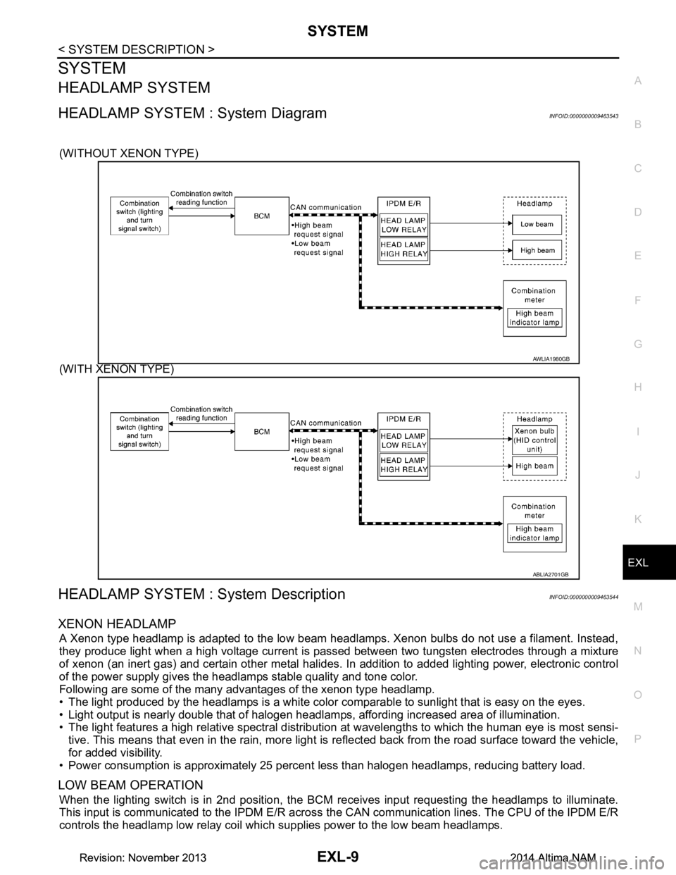
HEADLAMP SYSTEM : System DiagramINFOID:0000000009463543
(WITHOUT XENON TYPE)
(WITH XENON TYPE)
HEADLAMP SYSTEM : System DescriptionINFOID:0000000009463544
XENON HEADLAMP
A Xenon type headlamp is adapted to the low beam headlamps. Xenon bulbs do not use a filament. Instead,
they produce light when a high voltage current is pa ssed between two tungsten electrodes through a mixture
of xenon (an inert gas) and certain other metal halides. In addition to added lighting power, electronic control
of the power supply gives the headlamps stable quality and tone color.
Following are some of the many advantages of the xenon type headlamp.
• The light produced by the headlamps is a white color comparable to sunlight that is easy on the eyes.
• Light output is nearly double that of halogen headl amps, affording increased area of illumination.
• The light features a high relative spectral distributi on at wavelengths to which the human eye is most sensi-
tive. This means that even in the rain, more light is reflected back from the road surface toward the vehicle,
for added visibility.
• Power consumption is approximately 25 percent less than halogen headlamps, reducing battery load.
LOW BEAM OPERATION
When the lighting switch is in 2nd position, the BCM receives input requesting the headlamps to illuminate.
This input is communicated to the IPDM E/R across the CAN communication lines. The CPU of the IPDM E/R
controls the headlamp low relay coil which supplies power to the low beam headlamps.
AWLIA1980GB
ABLIA2701GB
Revision: November 20132014 Altima NAMRevision: November 20132014 Altima NAM
Page 2470 of 4801

FAX-18
< UNIT DISASSEMBLY AND ASSEMBLY >
FRONT DRIVE SHAFT
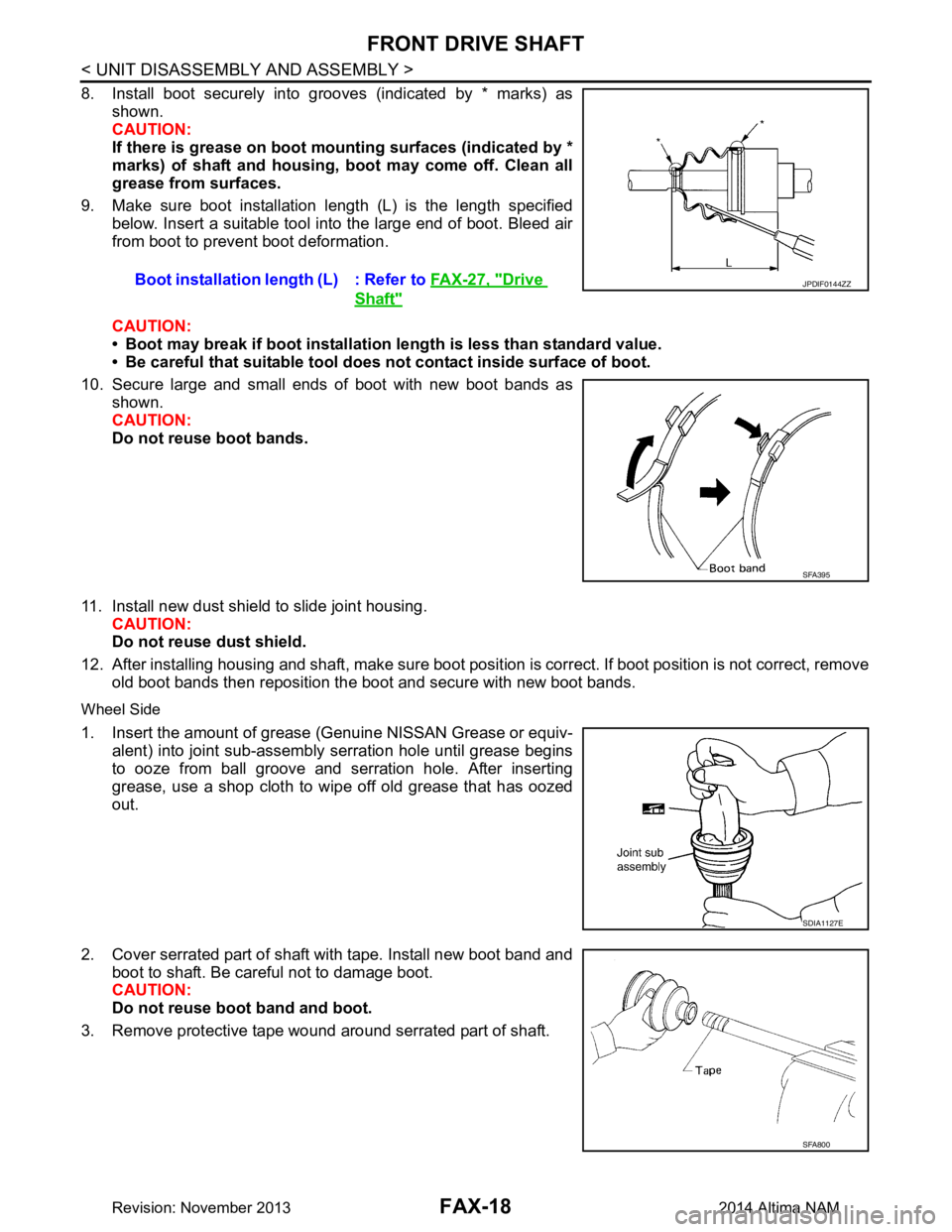
8. Install boot securely into grooves (indicated by * marks) asshown.
CAUTION:
If there is grease on boot mounting surfaces (indicated by *
marks) of shaft and housing, boot may come off. Clean all
grease from surfaces.
9. Make sure boot installation length (L) is the length specified below. Insert a suitable tool into the large end of boot. Bleed air
from boot to prevent boot deformation.
CAUTION:
• Boot may break if boot installation length is less than standard value.
• Be careful that suitable tool does not contact inside surface of boot.
10. Secure large and small ends of boot with new boot bands as shown.
CAUTION:
Do not reuse boot bands.
11. Install new dust shield to slide joint housing. CAUTION:
Do not reuse dust shield.
12. After installing housing and shaft, make sure boot posit ion is correct. If boot position is not correct, remove
old boot bands then reposition the boot and secure with new boot bands.
Wheel Side
1. Insert the amount of grease (Genuine NISSAN Grease or equiv-
alent) into joint sub-assembly serration hole until grease begins
to ooze from ball groove and serration hole. After inserting
grease, use a shop cloth to wipe off old grease that has oozed
out.
2. Cover serrated part of shaft with tape. Install new boot band and boot to shaft. Be careful not to damage boot.
CAUTION:
Do not reuse boot band and boot.
3. Remove protective tape wound around serrated part of shaft. Boot installation length (L) : Refer to
FAX-27, "Drive
Shaft"
JPDIF0144ZZ
SFA395
SDIA1127E
SFA800
Revision: November 20132014 Altima NAM
Page 2471 of 4801

FRONT DRIVE SHAFTFAX-19
< UNIT DISASSEMBLY AND ASSEMBLY >
CEF
G H
I
J
K L
M A
B
FA X
N
O P
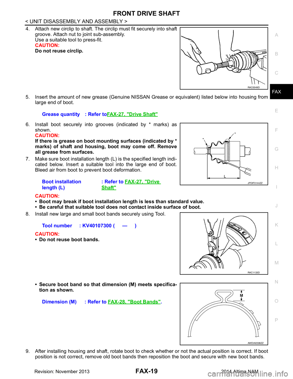
4. Attach new circlip to shaft. The circlip must fit securely into shaft groove. Attach nut to joint sub-assembly.
Use a suitable tool to press-fit.
CAUTION:
Do not reuse circlip.
5. Insert the amount of new grease (Genuine NISSAN Grease or equivalent) listed below into housing from
large end of boot.
6. Install boot securely into grooves (indicated by * marks) as shown.
CAUTION:
If there is grease on boot mounting surfaces (indicated by *
marks) of shaft and housing, boot may come off. Remove
all grease from surfaces.
7. Make sure boot installation length (L) is the specified length indi- cated below. Insert a suitable tool into the large end of boot.
Bleed air from boot to prevent boot deformation.
CAUTION:
• Boot may break if boot installation le ngth is less than standard value.
• Be careful that suitable tool does not contact inside surface of boot.
8. Install new large and small boot bands securely using Tool.
CAUTION:
• Do not reuse boot bands.
• Secure boot band so that dimension (M) meets specifica- tion as shown.
9. After installing housing and shaft, rotate boot to check whether or not the actual position is correct. If boot
position is not correct, remove old boot bands t hen reposition the boot and secure with new boot bands.
RAC0049D
Grease quantity : Refer toFAX-27, "Drive Shaft"
Boot installation
length (L) : Refer to
FAX-27, "Drive
Shaft"
Tool number : KV40107300 ( — )
JPDIF0144ZZ
RAC1133D
Dimension (M) : Refer to FAX-28, "Boot Bands".
AWDIA0598ZZ
Revision: November 20132014 Altima NAM