Page 4147 of 4801
ST-44
< UNIT DISASSEMBLY AND ASSEMBLY >
STEERING GEAR AND LINKAGE
2. Install large end (1) of boot (2) to gear housing assembly.
3. Install small end (3) of boot (2) to inner socket boot mounting groove.
4. Install boot clamp to boot small end.
5. Install boot clamp to boot large end using Tool. CAUTION:
Do not reuse boot clamps.
6. Adjust inner socket to standard length (L), and then tighten lock nut to the specified torque. Check length of inner socket (L)
again after tightening lock nut. Make sure that the length is the
standard.
CAUTION:
Adjust toe-in after this proced ure. The length achieved after
toe-in adjustment is not necessarily the above value.
AWGIA0107ZZ
Tool number : KV40107300 ( — )
AST139
Inner socket length (L) : Refer to ST-47, "Power
Steering Gear".
SGIA0167E
Revision: November 20132014 Altima NAMRevision: November 20132014 Altima NAM
Page 4149 of 4801

ST-46
< SERVICE DATA AND SPECIFICATIONS (SDS)
SERVICE DATA AND SPECIFICATIONS (SDS)
SERVICE DATA AND SPECIFICATIONS (SDS)
SERVICE DATA AND SPECIFICATIONS (SDS)
Steering WheelINFOID:0000000009461281
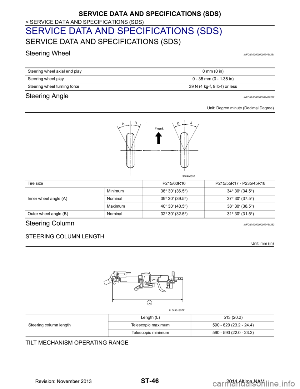
Steering AngleINFOID:0000000009461282
Unit: Degree minute (Decimal Degree)
Steering ColumnINFOID:0000000009461283
STEERING COLUMN LENGTH
Unit: mm (in)
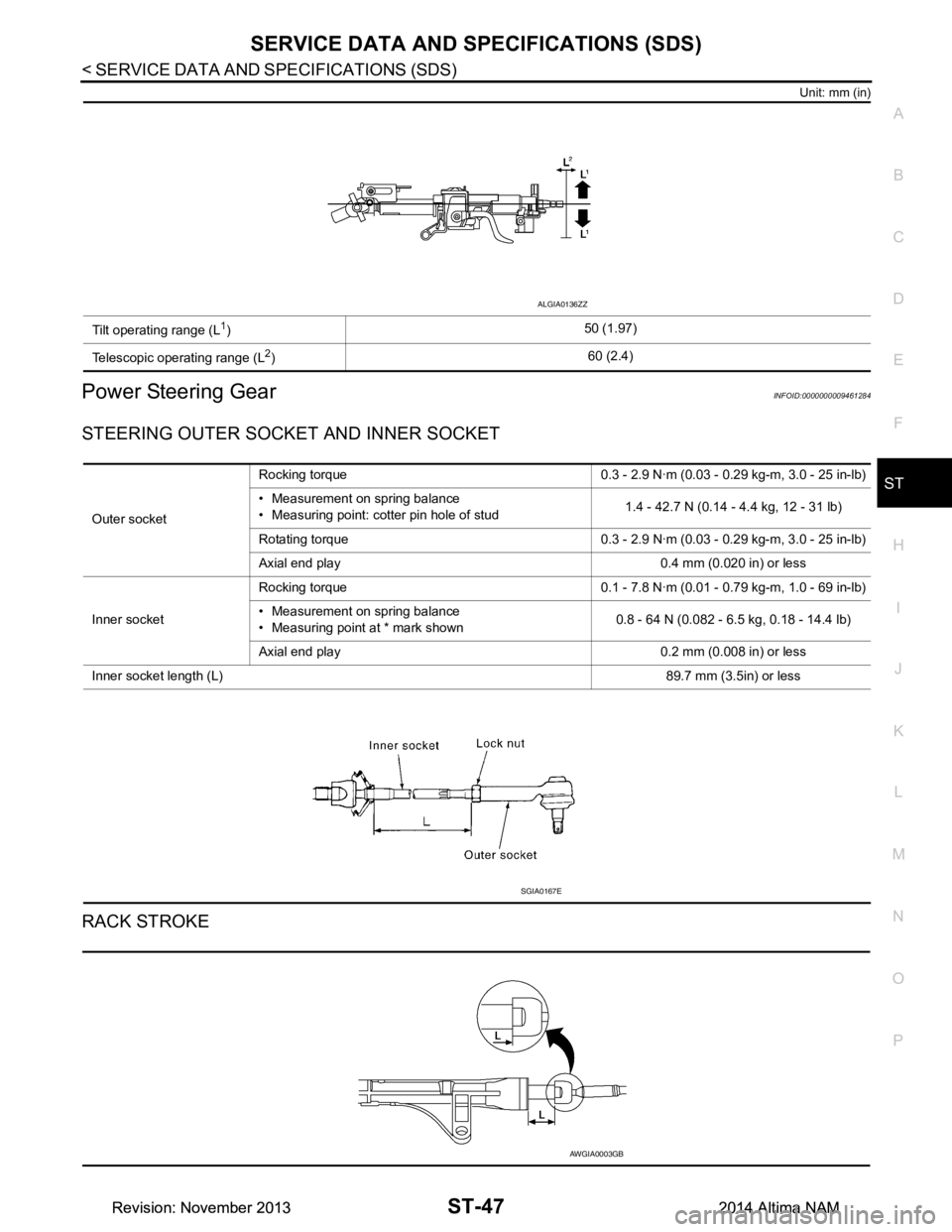
TILT MECHANISM OPERATING RANGE
Steering wheel axial end play 0 mm (0 in)
Steering wheel play 0 - 35 mm (0 - 1.38 in)
Steering wheel turning force 3 9 N (4 kg-f, 9 lb-f) or less
Tire size P215/60R16 P215/55R17 - P235/45R18
Inner wheel angle (A) Minimum 36
° 30 ′ (36.5 °)34 ° 30 ′ (34.5 °)
Nominal 39 ° 30 ′ (39.5 °)37 ° 30 ′ (37.5 °)
Maximum 40 ° 30 ′ (40.5 °)38 ° 30 ′ (38.5 °)
Outer wheel angle (B) Nominal 32 ° 30 ′ (32.5 °)31 ° 30 ′ (31.5 °)
SGIA0055E
Steering column length Length (L) 513 (20.2)
Telescopic maximum 590 - 620 (23.2 - 24.4) Telescopic minimum 560 - 590 (22.0 - 23.2)
ALGIA0135ZZ
Revision: November 20132014 Altima NAMRevision: November 20132014 Altima NAM
Page 4150 of 4801

SERVICE DATA AND SPECIFICATIONS (SDS)ST-47
< SERVICE DATA AND SPECIFICATIONS (SDS)
C
D E
F
H I
J
K L
M A
B
ST
N
O P
Unit: mm (in)
Power Steering GearINFOID:0000000009461284
STEERING OUTER SOCK ET AND INNER SOCKET
RACK STROKE
Tilt operating range (L1) 50 (1.97)
Telescopic operating range (L
2) 60 (2.4)
ALGIA0136ZZ
Outer socketRocking torque 0.3 - 2.9 N·m (0.0
3 - 0.29 kg-m, 3.0 - 25 in-lb)
• Measurement on spring balance
• Measuring point: cotter pin hole of stud 1.4 - 42.7 N (0.14 - 4.4 kg, 12 - 31 lb)
Rotating torque 0.3 - 2.9 N·m (0.03 - 0.29 kg-m, 3.0 - 25 in-lb)
Axial end play 0.4 mm (0.020 in) or less
Inner socket Rocking torque 0.1 - 7.8 N·m (0.0
1 - 0.79 kg-m, 1.0 - 69 in-lb)
• Measurement on spring balance
• Measuring point at * mark shown 0.8 - 64 N (0.082 - 6.5 kg, 0.18 - 14.4 lb)
Axial end play 0.2 mm (0.008 in) or less
Inner socket length (L) 89.7 mm (3.5in) or less
SGIA0167E
AWGIA0003GB
Revision: November 20132014 Altima NAMRevision: November 20132014 Altima NAM
Page 4308 of 4801
![NISSAN TEANA 2014 Service Manual
U0300 CAN COMMUNICATION DATATM-93
< DTC/CIRCUIT DIAGNOSIS > [CVT: RE0F10D]
C
EF
G H
I
J
K L
M A
B
TM
N
O P
U0300 CAN COMMUNICATION DATA
DTC LogicINFOID:0000000009464029
DTC DETECTION LOGIC
DTC CONF NISSAN TEANA 2014 Service Manual
U0300 CAN COMMUNICATION DATATM-93
< DTC/CIRCUIT DIAGNOSIS > [CVT: RE0F10D]
C
EF
G H
I
J
K L
M A
B
TM
N
O P
U0300 CAN COMMUNICATION DATA
DTC LogicINFOID:0000000009464029
DTC DETECTION LOGIC
DTC CONF](/manual-img/5/57390/w960_57390-4307.png)
U0300 CAN COMMUNICATION DATATM-93
< DTC/CIRCUIT DIAGNOSIS > [CVT: RE0F10D]
C
EF
G H
I
J
K L
M A
B
TM
N
O P
U0300 CAN COMMUNICATION DATA
DTC LogicINFOID:0000000009464029
DTC DETECTION LOGIC
DTC CONFIRMATION PROCEDURE
1.PREPARATION BEFORE WORK
If another “DTC CONFIRMATION PROC EDURE” occurs just before, turn ignition switch OFF and wait for at
least 10 seconds, then perform the next test.
>> GO TO 2.
2.CHECK DTC DETECTION
With CONSULT
1. Start the engine and wait for 5 seconds or more.
2. Check the DTC.
Is
“U0300” detected?
YES >> Go to TM-93, "Diagnosis Procedure".
NO >> INSPECTION END
Diagnosis ProcedureINFOID:0000000009464030
1.CONTROL UNIT CHECK
Check the number of control units replaced before “U0300” is detected.
Is one control unit replaced?
YES >> The specification of the control unit replac ed may be incorrect. Check the part number and the
specification.
NO >> GO TO 2.
2.CONTROL UNIT CHECK
With CONSULT
1. Remove one of the control unit replaced.
2. Assemble the old control unit before replacement.
3. Turn ignition switch ON, and wait for 2 seconds or more.
4. Select “Self Diagnostic Results” in “TRANSMISSION”.
Is
“U0300”detected?
YES >> Turn OFF the ignition switch and check other control units in the same manner.
NO >> The specification of the control unit remov ed may be incorrect. Check the part number and the
specification.
DTC CONSULT screen terms
(Trouble diagnosis content) DTC detection condition Possible causes
U0300 CAN COMM DATA
(Internal Control Module Soft-
ware Incompatibility) When the ignition switch is ON, the data length
transmitted from each control unit is shorter
than the specified length and the status contin-
ues for 2 seconds or more. Control unit other than TCM
Revision: November 20132014 Altima NAMRevision: November 20132014 Altima NAM
Page 4404 of 4801
CONTROL VALVETM-189
< REMOVAL AND INSTALLATION > [CVT: RE0F10D]
C
EF
G H
I
J
K L
M A
B
TM
N
O P
18. Remove the lip seal (1) from the transaxle case. CAUTION:
Do not reuse lip seal.
INSTALLATION
1. Install the lip seal (1) to the transaxle case.
CAUTION:
Do not reuse lip seal.
2. Install terminal cord assembly (1) to the transaxle case. CAUTION:
Connect the CVT unit connector with the stopper facing up,
and then press in until it clicks.
3. Install the control valve to the transaxle case. CAUTION:
• Do not pinch the harness between th e control valve and the transaxle case.
• Do not drop the control valve, ra tio control valve and manual shaft.
4. Secure the control valve using the control valve bolts (A) and (B).
: Front
JPDIA0661ZZ
: Front
JPDIA0661ZZ
JSDIA2634ZZ
: Front
Bolt Bolt length (mm) Number of bolts A54 8
B44 1
AWDIA1059ZZ
Revision: November 20132014 Altima NAMRevision: November 20132014 Altima NAM
Page 4405 of 4801
![NISSAN TEANA 2014 Service Manual
TM-190
< REMOVAL AND INSTALLATION >[CVT: RE0F10D]
CONTROL VALVE
5. Connect the control valve harness connectors (A).
CAUTION:
• Do not pinch the harness between the control valve and the transaxle NISSAN TEANA 2014 Service Manual
TM-190
< REMOVAL AND INSTALLATION >[CVT: RE0F10D]
CONTROL VALVE
5. Connect the control valve harness connectors (A).
CAUTION:
• Do not pinch the harness between the control valve and the transaxle](/manual-img/5/57390/w960_57390-4404.png)
TM-190
< REMOVAL AND INSTALLATION >[CVT: RE0F10D]
CONTROL VALVE
5. Connect the control valve harness connectors (A).
CAUTION:
• Do not pinch the harness between the control valve and the transaxle case.
• Securely insert the harness connector until it clicks and
locks.
6. Install CVT fluid temperature sensor bracket (1).
7. Install the bracket (1).
8. Install O-ring to oil strainer assembly. CAUTION:
• Do not reuse O-ring.
• Apply CVT fluid NS-3 to O-ring.
9. Install the oil strainer assembly (1) using the oil strainer assem- bly bolts (A) and (B).
NOTE:
Remove the bracket and adjust the position again if the bolt hole
positions are not aligned.
10. Install the manual plate (1) while aligning with the groove (A) of the manual valve.
CAUTION:
Assemble the manual plate while aligning its end with the
cutout ( ) of the manual valve.
11. Install the spring washer (2) and the lock-nut (3), and then tighten to the specified torque.
: Front
: Bolt
JSDIA3686ZZ
: Bolt
: Front
JPDIA0658ZZ
: Front
Bolt Bolt length (mm) Number of bolts A12 2
B44 1
(A) : Manual shaft : Front
JPDIA0657ZZ
JPDIA0962ZZ
Revision: November 20132014 Altima NAMRevision: November 20132014 Altima NAM
Page 4423 of 4801
![NISSAN TEANA 2014 Service Manual
TM-208
< UNIT REMOVAL AND INSTALLATION >[CVT: RE0F10D]
TRANSAXLE ASSEMBLY
• When installing the drive plate to torque converter nuts,
tighten them temporarily. then tighten the nuts to the
specifi NISSAN TEANA 2014 Service Manual
TM-208
< UNIT REMOVAL AND INSTALLATION >[CVT: RE0F10D]
TRANSAXLE ASSEMBLY
• When installing the drive plate to torque converter nuts,
tighten them temporarily. then tighten the nuts to the
specifi](/manual-img/5/57390/w960_57390-4422.png)
TM-208
< UNIT REMOVAL AND INSTALLATION >[CVT: RE0F10D]
TRANSAXLE ASSEMBLY
• When installing the drive plate to torque converter nuts,
tighten them temporarily. then tighten the nuts to the
specified torque.
Inspection and AdjustmentINFOID:0000000009464162
INSPECTION BEFORE INSTALLATION
After inserting a torque converter to the CVT, check dimension (A)
with in the reference value limit.
INSPECTION AFTER INSTALLATION
Check the following items:
• CVT fluid leakage, refer to TM-178, "Inspection"
.
• For CVT position, refer to TM-180, "Inspection"
.
• Start the engine and check for coolant leakage from the parts which are removed and reinstalled.
ADJUSTMENT AFTER INSTALLATION
• Adjust the CVT fluid level. Refer to TM-84, "Adjustment".
• Perform "ADDITIONAL SERVICE WHEN REPLACE TRANSAXLE ASSEMBLY". Refer to TM-81, "Descrip-
tion".
Bolt length
"" mm
(in) 45 (1.77) 45 (1.77) 45 (1.77) 35 (1.38) 45 (1.77) 45 (1.77)
Tightening
torque N·m
(kg-m, ft-lb) 35.3
(3.6, 26) 74.5
(7.6, 55) 42.7
(4.4, 31) 42.7
(4.4, 31) 74.5
(7.6, 55) 48.0
(4.9, 35)
Bolt No.123456
B: Scale
C : Straightedge
Dimension (A) : Refer to TM-212, "Torque Converter".
JPDIA0115ZZ
Revision: November 20132014 Altima NAMRevision: November 20132014 Altima NAM
Page 4510 of 4801
![NISSAN TEANA 2014 Service Manual
U0300 CAN COMMUNICATION DATATM-295
< DTC/CIRCUIT DIAGNOSIS > [CVT: RE0F10E]
C
EF
G H
I
J
K L
M A
B
TM
N
O P
U0300 CAN COMMUNICATION DATA
DTC LogicINFOID:0000000009464246
DTC DETECTION LOGIC
DTC CON NISSAN TEANA 2014 Service Manual
U0300 CAN COMMUNICATION DATATM-295
< DTC/CIRCUIT DIAGNOSIS > [CVT: RE0F10E]
C
EF
G H
I
J
K L
M A
B
TM
N
O P
U0300 CAN COMMUNICATION DATA
DTC LogicINFOID:0000000009464246
DTC DETECTION LOGIC
DTC CON](/manual-img/5/57390/w960_57390-4509.png)
U0300 CAN COMMUNICATION DATATM-295
< DTC/CIRCUIT DIAGNOSIS > [CVT: RE0F10E]
C
EF
G H
I
J
K L
M A
B
TM
N
O P
U0300 CAN COMMUNICATION DATA
DTC LogicINFOID:0000000009464246
DTC DETECTION LOGIC
DTC CONFIRMATION PROCEDURE
1.PREPARATION BEFORE WORK
If another “DTC CONFIRMATION PROC EDURE” occurs just before, turn ignition switch OFF and wait for at
least 10 seconds, then perform the next test.
>> GO TO 2.
2.CHECK DTC DETECTION
With CONSULT
1. Start the engine and wait for 5 seconds or more.
2. Check the DTC.
Is
“U0300” detected?
YES >> Go to TM-295, "Diagnosis Procedure".
NO >> INSPECTION END
Diagnosis ProcedureINFOID:0000000009464247
1.CONTROL UNIT CHECK
Check the number of control units replaced before “U0300” is detected.
Is one control unit replaced?
YES >> The specification of the control unit replac ed may be incorrect. Check the part number and the
specification.
NO >> GO TO 2.
2.CONTROL UNIT CHECK
With CONSULT
1. Remove one of the control unit replaced.
2. Assemble the old control unit before replacement.
3. Turn ignition switch ON, and wait for 2 seconds or more.
4. Select “Self Diagnostic Results” in “TRANSMISSION”.
Is
“U0300”detected?
YES >> Turn OFF the ignition switch and check other control units in the same manner.
NO >> The specification of the control unit remov ed may be incorrect. Check the part number and the
specification.
DTC CONSULT screen terms
(Trouble diagnosis content) DTC detection condition Possible causes
U0300 CAN COMM DATA
(Internal Control Module Soft-
ware Incompatibility) When the ignition switch is ON, the data length
transmitted from each control unit is shorter
than the specified length and the status contin-
ues for 2 seconds or more. Control unit other than TCM
Revision: November 20132014 Altima NAMRevision: November 20132014 Altima NAM