2014 NISSAN TEANA REMOVAL
[x] Cancel search: REMOVALPage 97 of 4801

BR-1
BRAKES
C
D E
G H
I
J
K L
M
SECTION BR
A
B
BR
N
O P
CONTENTS
BRAKE SYSTEM
PRECAUTION ................ ...............................3
PRECAUTIONS .............................................. .....3
Precaution for Supplemental Restraint System
(SRS) "AIR BAG" and "SEAT BELT PRE-TEN-
SIONER" ............................................................. ......
3
Precaution for Procedure without Cowl Top Cover ......3
Precaution for Brake System ....................................3
PREPARATION ............................................5
PREPARATION .............................................. .....5
Special Service Tool ........................................... ......5
Commercial Service Tool ..........................................5
SYSTEM DESCRIPTION ..............................6
NOISE, VIBRATION AND HARSHNESS
(NVH) TROUBLESHOOTING ........................ .....
6
NVH Troubleshooting Chart ................................ ......6
BASIC INSPECTION ....................................7
BRAKE PEDAL .............................................. .....7
Inspection ............................................................ ......7
BRAKE FLUID .....................................................8
Inspection ............................................................ ......8
BRAKE MASTER CYLINDER ........................ .....9
Inspection ............................................................ ......9
On Board Inspection .................................................9
BRAKE BOOSTER ............................................10
Inspection ............................................................ ....10
FRONT DISC BRAKE .................................... ....11
BRAKE PAD .......................................................... ....11
BRAKE PAD : Inspection ........................................11
DISC ROTOR ......................................................... ....11
DISC ROTOR : Inspection ......................................11
REAR DISC BRAKE .........................................12
BRAKE PAD .......................................................... ....12
BRAKE PAD : Inspection .........................................12
DISC ROTOR ......................................................... ....12
DISC ROTOR : Inspection .......................................12
PERIODIC MAINTENANCE ........................13
BRAKE PEDAL ................................ .................13
Inspection and Adjustment .................................. ....13
BRAKE FLUID ................................. .................14
Drain and Refill .................................................... ....14
Bleeding Brake System ...........................................14
FRONT DISC BRAKE .......................................16
Brake Burnishing ................................................. ....16
REAR DISC BRAKE .........................................17
Brake Burnishing ................................................. ....17
REMOVAL AND INSTALLATION ...............18
BRAKE PEDAL ................................ .................18
Exploded View ..................................................... ....18
Removal and Installation .........................................18
BRAKE PIPING ................................ .................20
FRONT ................................................................... ....20
FRONT : Exploded View .........................................20
FRONT : Hydraulic Piping .......................................21
FRONT : Removal and Installation ..........................21
REAR ..................................................................... ....23
REAR : Exploded View ............................................23
REAR : Hydraulic Piping ..........................................24
REAR : Removal and Installation ............................24
BRAKE MASTER CYLINDER ..........................26
Exploded View .........................................................26
Removal and Installation .........................................26
Revision: November 20132014 Altima NAM
Page 98 of 4801

BR-2
BRAKE BOOSTER ............................................28
Exploded View ..................................................... ...28
Removal and Installation - QR25DE .......................28
Removal and Installation - VQ35DE .................... ...29
VACUUM LINES ................................................31
Exploded View ..................................................... ...31
Removal and Installation ........................................32
Inspection After Removal .......................................33
FRONT DISC BRAKE ..................................... ...34
BRAKE PAD .......................................................... ...34
BRAKE PAD : Exploded View ................................34
BRAKE PAD : Removal and Installation .................34
BRAKE CALIPER ASSEMBLY ............................. ...35
BRAKE CALIPER ASSEMBLY : Exploded View ....36
BRAKE CALIPER ASSEMBLY : Removal and In-
stallation .............................................................. ...
36
REAR DISC BRAKE ..........................................38
BRAKE PAD .......................................................... ...38
BRAKE PAD : Exploded View ................................38
BRAKE PAD : Removal and Installation .................38
BRAKE CALIPER ASSEMBLY ............................. ...39
BRAKE CALIPER ASSEMBLY : Exploded View ....39
BRAKE CALIPER ASSEMBLY : Removal and In-
stallation .............................................................. ...
40
UNIT DISASSEMBLY AND ASSEMBLY ...42
FRONT DISC BRAKE .......................................42
BRAKE CALIPER ASSEMBLY ................................42
BRAKE CALIPER ASSEMBLY : Exploded View . ...42
BRAKE CALIPER ASSEMBLY : Disassembly ........42
BRAKE CALIPER ASSEMBLY : Inspection After
Disassembly ......................................................... ...
43
BRAKE CALIPER ASSEMBLY : Assembly ............43
REAR DISC BRAKE ....................................... ...45
BRAKE CALIPER ASSEMBLY ................................45
BRAKE CALIPER ASSEMBLY : Exploded View . ...45
BRAKE CALIPER ASSEMBLY : Disassembly ........45
BRAKE CALIPER ASSEMBLY : Inspection After
Disassembly ......................................................... ...
46
BRAKE CALIPER ASSEMBLY : Assembly ............46
SERVICE DATA A ND SPECIFICATIONS
(SDS) ............... ...........................................
48
SERVICE DATA AND SPECIFICATIONS
(SDS) .............................................................. ...
48
General Specifications ......................................... ...48
Brake Pedal ............................................................48
Check Valve ............................................................49
Brake Booster .........................................................49
Front Disc Brake .....................................................49
Rear Disc Brake ......................................................49
Revision: November 20132014 Altima NAM
Page 99 of 4801

PRECAUTIONSBR-3
< PRECAUTION >
C
D E
G H
I
J
K L
M A
B
BR
N
O P
PRECAUTION
PRECAUTIONS
Precaution for Supplemental Restraint System (SRS) "AIR BAG" and "SEAT BELT
PRE-TENSIONER"
INFOID:0000000009951709
The Supplemental Restraint System such as “A IR BAG” and “SEAT BELT PRE-TENSIONER”, used along
with a front seat belt, helps to reduce the risk or severi ty of injury to the driver and front passenger for certain
types of collision. Information necessary to service t he system safely is included in the SR and SB section of
this Service Manual.
WARNING:
• To avoid rendering the SRS inoper ative, which could increase the risk of personal injury or death in
the event of a collision which would result in air bag inflation, all maintenance must be performed by
an authorized NISSAN/INFINITI dealer.
• Improper maintenance, including in correct removal and installation of the SRS, can lead to personal
injury caused by unintentional act ivation of the system. For removal of Spiral Cable and Air Bag
Module, see the SR section.
• Do not use electrical test equipm ent on any circuit related to the SRS unless instructed to in this
Service Manual. SRS wiring harnesses can be identi fied by yellow and/or orange harnesses or har-
ness connectors.
PRECAUTIONS WHEN USING POWER TOOLS (AIR OR ELECTRIC) AND HAMMERS
WARNING:
• When working near the Airbag Diagnosis Sensor Un it or other Airbag System sensors with the Igni-
tion ON or engine running, DO NOT use air or el ectric power tools or strike near the sensor(s) with a
hammer. Heavy vibration could activate the sensor( s) and deploy the air bag(s), possibly causing
serious injury.
• When using air or electric power tools or hammers , always switch the Ignition OFF, disconnect the
battery and wait at least three mi nutes before performing any service.
Precaution for Procedure without Cowl Top CoverINFOID:0000000009463677
When performing the procedure after removing cowl top cover, cover
the lower end of windshield with urethane, etc.
Precaution for Brake SystemINFOID:0000000009463678
WARNING:
Clean any dust from the front brake and rear brake wi th a vacuum dust collector. Never blow with com-
pressed air.
CAUTION:
• Brake fluid use. Refer to MA-11, "FOR USA AND CANADA : Fluids and Lubricants"
.
• Do not reuse drained brake fluid.
• Do not spill or splash brake fluid on painted su rfaces. Brake fluid may seriously damage paint. Wipe
it off immediately and wash with wa ter if it gets on a painted surface.
• Always clean with new brake fluid when cleaning th e master cylinder, brake caliper and other com-
ponents.
• Do not use mineral oils such as gasoline or light oil to clean. They may damage rubber parts and
cause improper operation.
• Always loosen the brake tube flar e nut with a flare nut wrench.
PIIB3706J
Revision: November 20132014 Altima NAM
Page 110 of 4801

BR-14
< PERIODIC MAINTENANCE >
BRAKE FLUID
BRAKE FLUID
Drain and RefillINFOID:0000000009463692
CAUTION:
• Do not spill or splash brake fluid on painted surf aces. Brake fluid may damage paint. If brake fluid is
splashed on painted areas, wash it away with water immediately.
• Prior to repair, turn the ignition switch OFF, disconnect the ABS actuator and electric unit (control
unit) connector or negative battery terminal. Refer to PG-73, "Removal and Installation (Battery)"
.
• Refill brake system with new brake fluid. Refer to MA-11, "FOR USA AND CANADA : Fluids and
Lubricants".
• Do not reuse drained brake fluid.
DRAINING
1. Turn ignition switch OFF and disconnect ABS actuat or and electric unit (control unit) connector or nega-
tive battery terminal. Refer to PG-73, "Removal and Installation (Battery)"
.
2. Connect a vinyl tube to bleeder valve.
3. Depress brake pedal, loosen bleeder valve, and gradually remove brake fluid.
REFILLING
1. Make sure no foreign material is in the reservoir, and refill withnew brake fluid.
CAUTION:
Do not reuse drained brake fluid.
2. Refill the brake system as follows: • Depress the brake pedal.
• Loosen bleeder valve.
• Slowly depress brake pedal to 2/3 of the brake pedal full
stroke.
• Tighten bleeder valve.
• Release brake pedal.
Repeat this operation at intervals of two or three seconds until
all old brake fluid is discharged. Add new brake flui d to master cylinder reservoir sub tank frequently.
CAUTION:
Do not allow master cylinder reservoir to empt y as this may cause damage to master cylinder
internal components.
3. Bleed the air out of the brake hydraulic system. Refer to BR-14, "Bleeding Brake System"
.
Bleeding Brake SystemINFOID:0000000009463693
BLEEDING BRAKE SYSTEM
CAUTION:
• While bleeding, pay attention to master cylinder fluid level.
• Prior to repair, turn the ignition switch OFF, disconnect the ABS actuator and electric unit (control
unit) connector or negative battery terminal. Refer to PG-73, "Removal and Installation (Battery)"
.
1. Connect a vinyl tube to rear right brake caliper bleeder valve.
2. Fully depress brake pedal ten times.
3. With brake pedal depressed, loosen bleeder valve to bleed air in brake line, and then tighten it immedi-
ately.
BRA0007D
ALFIA0274ZZ
Revision: November 20132014 Altima NAM
Page 114 of 4801

BR-18
< REMOVAL AND INSTALLATION >
BRAKE PEDAL
REMOVAL AND INSTALLATION
BRAKE PEDAL
Exploded ViewINFOID:0000000009463696
Removal and InstallationINFOID:0000000009463697
REMOVAL
1. Remove the instrument lower panel LH. Refer to IP-14, "Exploded View".
2. Remove the accelerator pedal. Refer to ACC-3, "Removal and Installation"
.
3. Disconnect the harness connectors from the stop lamp switch and ASCD cancel switch.
4. Remove the stop lamp switch and ASCD canc el switch from the brake pedal assembly.
5. Remove the snap pin (1) and clevis pin (2) from the brake pedal assembly.
CAUTION:
Do not reuse the snap pin or clevis pin.
6. Disconnect the brake booster clevis from the brake pedal assembly.
7. Disconnect the steering column assembly pinch bolt and position the steering column assembly aside to
gain access to the brake pedal assembly. Refer to ST-33, "Exploded View"
.
8. Remove the brake pedal assembly nuts. NOTE:
Remove the top brake pedal assembly nut first.
9. Remove the harness clips from the brake pedal assembly.
10. Remove the brake pedal assembly.
INSTALLATION
1. Snap pin 2. Brake pedal assembly 3. Brake pedal pad
4. Stop lamp switch 5. ASCD cancel switch 6. Clevis pin
AWFIA0931ZZ
JPFIA0019ZZ
Revision: November 20132014 Altima NAM
Page 115 of 4801

BRAKE PEDALBR-19
< REMOVAL AND INSTALLATION >
C
D E
G H
I
J
K L
M A
B
BR
N
O P
Installation is in the reverse order of removal.
CAUTION:
Do not reuse the snap pin or clevis pin.
• Adjust the brake pedal height after installing the brake pedal assembly. Refer to BR-13, "Inspection and
Adjustment".
• Tighten the clevis lock nut to the specified torque. Refer to BR-28, "Exploded View"
.
Revision: November 20132014 Altima NAM
Page 116 of 4801
BR-20
< REMOVAL AND INSTALLATION >
BRAKE PIPING
BRAKE PIPING
FRONT
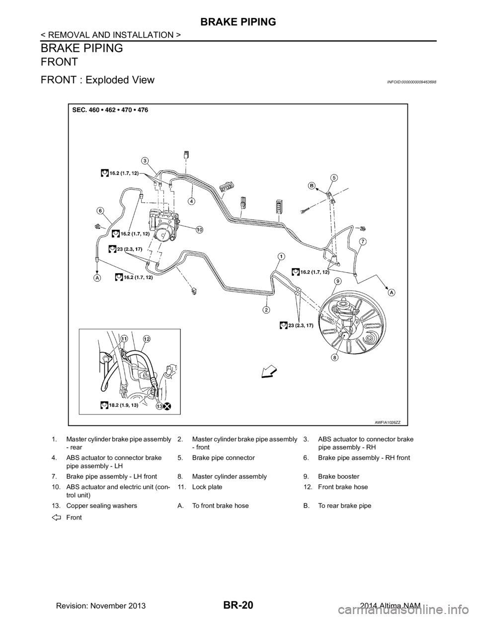
FRONT : Exploded ViewINFOID:0000000009463698
1. Master cylinder brake pipe assembly - rear 2. Master cylinder brake pipe assembly
- front 3. ABS actuator to connector brake
pipe assembly - RH
4. ABS actuator to connector brake
pipe assembly - LH 5. Brake pipe connector 6. Brake pipe assembly - RH front
7. Brake pipe assembly - LH front 8. Master cylinder assembly 9. Brake booster
10. ABS actuator and el ectric unit (con-
trol unit) 11. Lock plate 12. Front brake hose
13. Copper sealing washers A. To front brake hose B. To rear brake pipe Front
AWFIA1026ZZ
Revision: November 20132014 Altima NAM
Page 117 of 4801

BRAKE PIPINGBR-21
< REMOVAL AND INSTALLATION >
C
D E
G H
I
J
K L
M A
B
BR
N
O P
FRONT : Hydraulic PipingINFOID:0000000009463699
Four Channel Hydraulic Circuit
CAUTION:
• All hoses and piping (tubes) must be fr ee from excessive bending, twisting and pulling.
• Make sure there is no interference with other pa rts when turning steering both clockwise and coun-
terclockwise.
• The brake piping is an important safety part. If a brake fluid leak is detected, always disassemble the
parts. Replace applicable part with a new one, if necessary.
• Be careful not to splash brake fluid on painted areas; it may cause paint damage. If brake fluid is
splashed on painted areas, wash it away with water immediately.
• Do not bend or twist brake hose sharply, or strongly pull it.
• Do not reuse drained brake fluid.
• After installation of the ABS actuator and electri c unit (control unit), refill brake system with new
brake fluid. Then bleed the ai r from the system. Refer to BR-14, "Bleeding Brake System"
.
FRONT : Removal and InstallationINFOID:0000000009463700
REMOVAL
NOTE:
When removing components such as hoses, tubes/lines, etc. , cap or plug openings to prevent fluid from spill-
ing.
1. Remove the wheel and tire using power tool. Refer to WT-55, "Adjustment"
.
2. Drain brake fluid. Refer to BR-14, "Drain and Refill"
.
AWFIA0910ZZ
1. ABS actuator and electric unit
(control unit) 2. Master cylinder 3. Booster
4. Connector A. Union bolt B. Flare nut M12
C. Flare nut M10
Revision: November 20132014 Altima NAM