2014 NISSAN TEANA fuel pressure
[x] Cancel search: fuel pressurePage 2491 of 4801
FUEL TANKFL-11
< REMOVAL AND INSTALLATION >
C
D E
F
G H
I
J
K L
M A
FL
NP
O
• As a guide, if the fuel tank is full the fuel leve
l reaches or is less than the level on the fuel gauge as
shown, when approximately 34 (9 US gal, 7 1/2 Imp gal) of fuel is drained from a full fuel tank.
3. Open the fuel filler cap to release the pressure inside the fuel tank.
4. Release fuel pressure from fuel line. Refer to EC-182, "Work Procedure"
(QR25DE), EC-687, "Work Pro-
cedure" (VQ35DE).
5. Remove rear seat cushion. Refer to SE-36, "Removal and Installation - Seat Assembly"
.
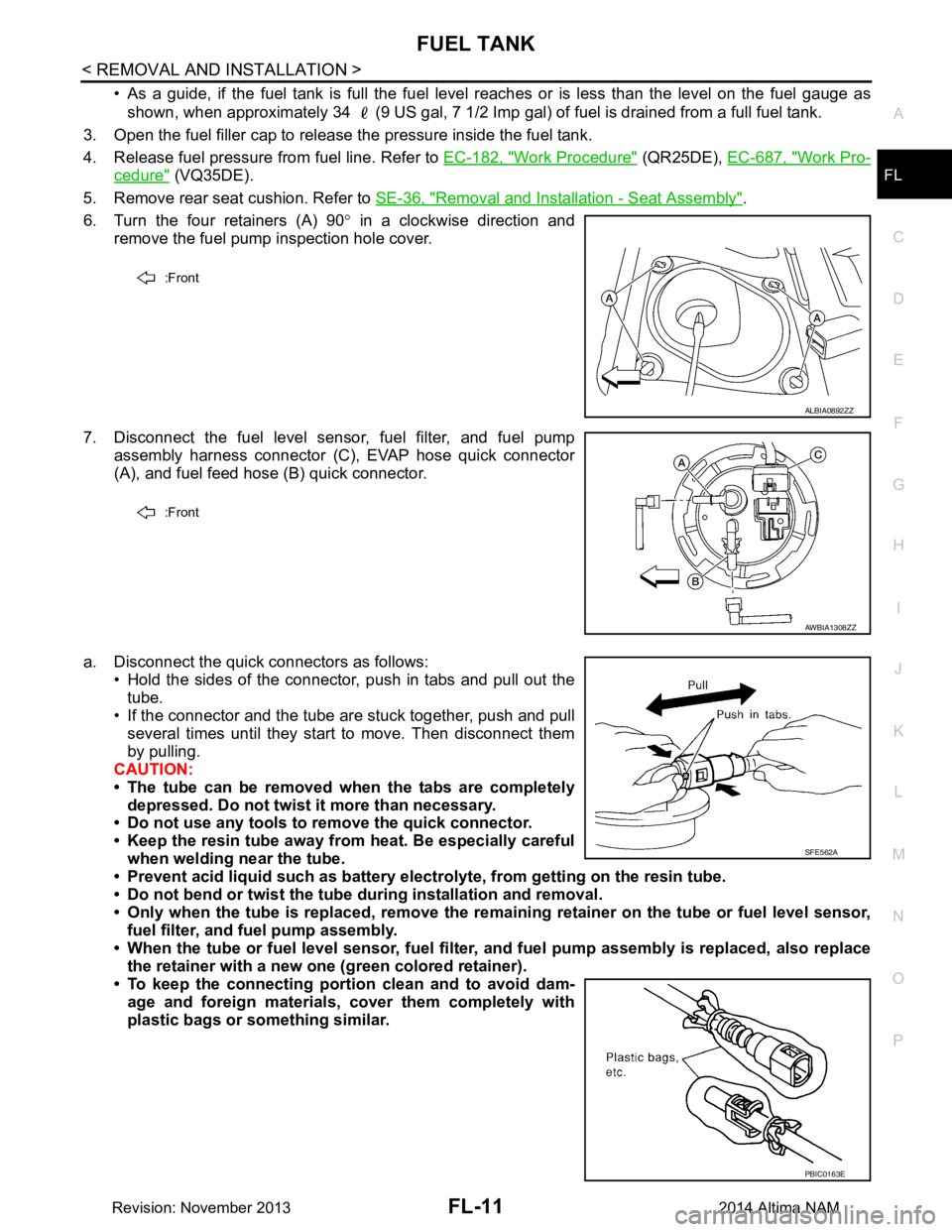
6. Turn the four retainers (A) 90 ° in a clockwise direction and
remove the fuel pump inspection hole cover.
7. Disconnect the fuel level sensor, fuel filter, and fuel pump assembly harness connector (C), EVAP hose quick connector
(A), and fuel feed hose (B) quick connector.
a. Disconnect the quick connectors as follows: • Hold the sides of the connector, push in tabs and pull out the
tube.
• If the connector and the tube are stuck together, push and pull
several times until they start to move. Then disconnect them
by pulling.
CAUTION:
• The tube can be removed when the tabs are completely depressed. Do not twist it more than necessary.
• Do not use any tools to remove the quick connector.
• Keep the resin tube away from heat. Be especially careful
when welding near the tube.
• Prevent acid liquid such as battery elect rolyte, from getting on the resin tube.
• Do not bend or twist the tube during installation and removal.
• Only when the tube is replaced, remove the remaining retainer on the tube or fuel level sensor,
fuel filter, and fuel pump assembly.
• When the tube or fuel level sen sor, fuel filter, and fuel pump assembly is replaced, also replace
the retainer with a new one (green colored retainer).
• To keep the connecting portio n clean and to avoid dam-
age and foreign materials, cover them completely with
plastic bags or something similar.
:Front
ALBIA0892ZZ
:Front
AWBIA1308ZZ
SFE562A
PBIC0163E
Revision: November 20132014 Altima NAM
Page 2494 of 4801
FL-14
< REMOVAL AND INSTALLATION >
EVAP CANISTER
EVAP CANISTER
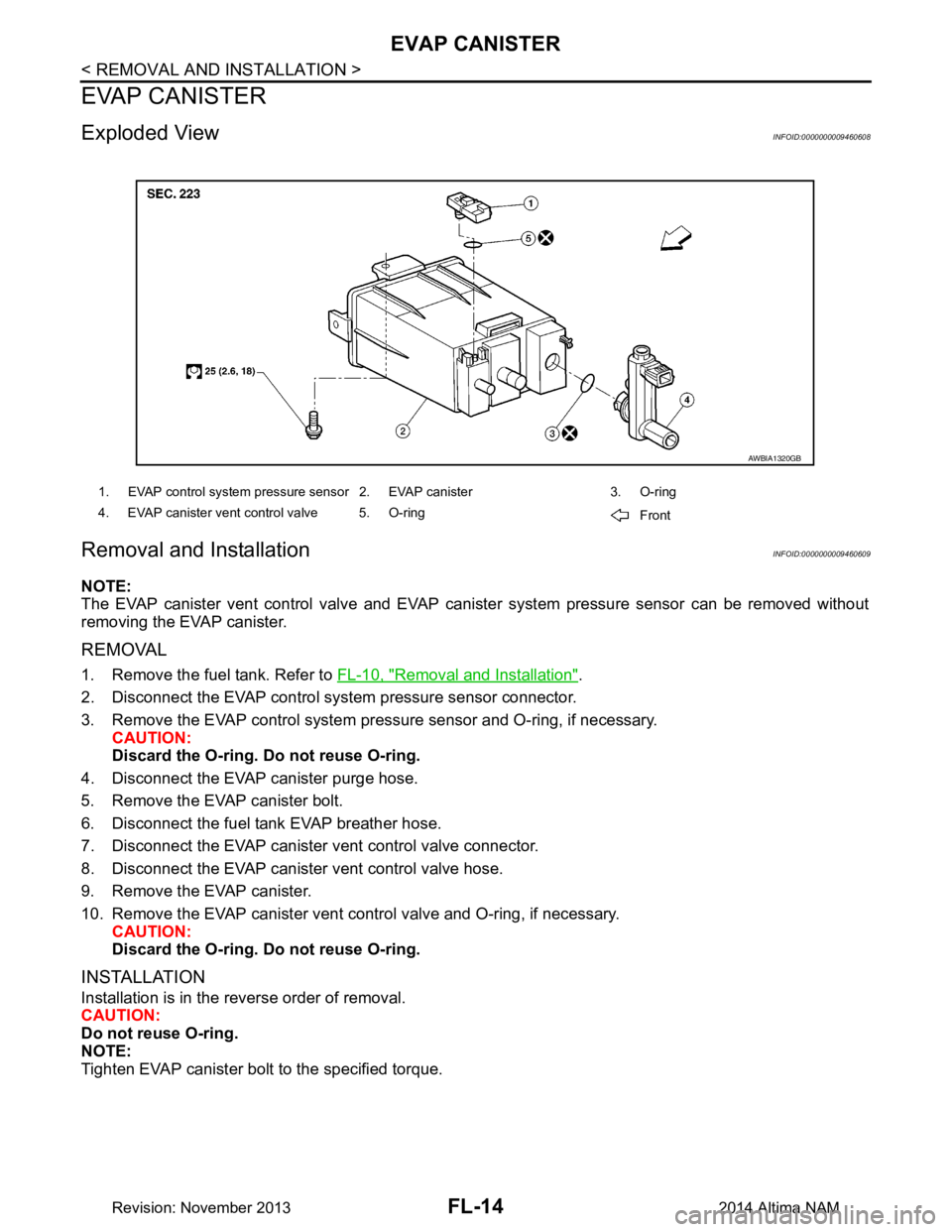
Exploded ViewINFOID:0000000009460608
Removal and InstallationINFOID:0000000009460609
NOTE:
The EVAP canister vent control valve and EVAP cani ster system pressure sensor can be removed without
removing the EVAP canister.
REMOVAL
1. Remove the fuel tank. Refer to FL-10, "Removal and Installation".
2. Disconnect the EVAP control system pressure sensor connector.
3. Remove the EVAP control system pressu re sensor and O-ring, if necessary.
CAUTION:
Discard the O-ring. Do not reuse O-ring.
4. Disconnect the EVAP canister purge hose.
5. Remove the EVAP canister bolt.
6. Disconnect the fuel tank EVAP breather hose.
7. Disconnect the EVAP canister vent control valve connector.
8. Disconnect the EVAP canister vent control valve hose.
9. Remove the EVAP canister.
10. Remove the EVAP canister vent c ontrol valve and O-ring, if necessary.
CAUTION:
Discard the O-ring. Do not reuse O-ring.
INSTALLATION
Installation is in the reverse order of removal.
CAUTION:
Do not reuse O-ring.
NOTE:
Tighten EVAP canister bolt to the specified torque.
1. EVAP control system pressure sensor 2. EVAP canister 3. O-ring
4. EVAP canister vent control valve 5. O-ring Front
AWBIA1320GB
Revision: November 20132014 Altima NAM
Page 2508 of 4801
FRONT SUSPENSION ASSEMBLYFSU-7
< PERIODIC MAINTENANCE >
C
D
F
G H
I
J
K L
M A
B
FSU
N
O P
PERIODIC MAINTENANCE
FRONT SUSPENSION ASSEMBLY
Inspection and AdjustmentINFOID:0000000009460626
INSPECTION
Make sure the mounting conditions (looseness, back lash) of each component and component conditions
(wear, damage) are normal.
LOWER BALL JOINT END PLAY
1. Set front wheels in a straight-ahead position. Do not depress brake pedal.
2. Place an iron bar or similar tool between upper link and steering knuckle.
3. Measure axial end play by prying it up and down.Refer to FSU-26, "Ball Joint"
.
CAUTION:
Be careful not to damage ball joint boot. Do not damage the installation position by applying
excessive force.
SHOCK ABSORBER
Check for oil leakage, damage and repl ace if malfunction is detected.
WHEEL ALIGNMENT
Description
Measure wheel alignment under unladen conditions.
NOTE:
"Unladen conditions" means that fuel, engine coolant, and lubricant are full. Spare tire, jack, hand tools and
mats are in designated positions.
General Information and Recommendations
• A four-wheel thrust alignment should be performed.
- This type of alignment is re commended for any NISSAN vehicle.
- The four-wheel "thrust" process helps ensure that t he vehicle is properly aligned and the steering wheel is
centered.
- The alignment rack itself should be capable of accepting any NISSAN vehicle.
- The rack should be checked to ensure that it is level.
• Make sure the machine is properly calibrated.
- Your alignment equipment should be regularly ca librated in order to give correct information.
- Check with the manufacturer of your specific equi pment for their recommended Service/Calibration Sched-
ule.
Preliminary Check
Check the following:
1. Tires for improper air pressure and wear.
2. Road wheels for runout. Refer to WT-60, "Road Wheel"
.
3. Wheel bearing axial end play. Refer to FAX-27, "Wheel Bearing"
.
4. Transverse link ball joint axial end play. Refer to FSU-11, "Removal and Installation"
.
5. Shock absorber operation.
6. Each mounting part of axle and suspension for looseness and deformation.
7. Each of suspension member, shock absorber, upper link and transverse link for cracks, deformation and other damage.
8. Vehicle height (posture).
Alignment Process
IMPORTANT:
Use only the alignment specificati ons listed in this Service Manual.
• When displaying the alignment settings, m any alignment machines use "indicators" Do not use these indi-
cators. : (Green/red, plus or minus, Go/No Go).
- The alignment specifications programmed into your machine that operate these indicators may not be cor-
rect.
Revision: November 20132014 Altima NAM
Page 2541 of 4801

ABBREVIATIONSGI-13
< HOW TO USE THIS MANUAL >
C
D E
F
G H
I
J
K L
M B
GI
N
O PABBREVIATIONS
Abbreviation ListINFOID:0000000009462979
The following ABBREVIATIONS are used:
A
B
C
D
ABBREVIATION DESCRIPTION A/C Air conditioner
A/C Air conditioning
A/F sensor Air fuel ratio sensor A/T Automatic transaxle/transmission
ABS Anti-lock braking system
ACCS Advance climate control system ACL Air cleaner
AP Accelerator pedal
APP Accelerator pedal position AV Audio visual
AVM Around view monitor
AWD All wheel drive
ABBREVIATION DESCRIPTION BARO Barometric pressureBCI Backup collision intervention
BCM Body control module
BLSD Brake limited slip differential BPP Brake pedal positionBSI Blind spot intervention
BSW Blind spot warning
ABBREVIATION DESCRIPTION CKP Crankshaft positionCL Closed loop
CMP Camshaft position CPP Clutch pedal positionCTP Closed throttle position
CVT Continuously variable transaxle/transmission
ABBREVIATION DESCRIPTION D
1Drive range first gear
D
2Drive range second gear
D
3Drive range third gear
D
4Drive range fourth gear
DCA Distance control assist
DDS Downhill drive support DFI Direct fuel injection system
DLC Data link connector
DTC Diagnostic trouble code
Revision: November 20132014 Altima NAMRevision: November 20132014 Altima NAM
Page 2542 of 4801

GI-14
< HOW TO USE THIS MANUAL >
ABBREVIATIONS
E
F
G
H
ABBREVIATION DESCRIPTION E/T Exhaust temperature
EBD Electric brake force distribution EC Engine control
ECL Engine coolant level
ECM Engine control module ECT Engine coolant temperature
ECV Electrical control valve
EEPROM Electrically erasable pr ogrammable read only memory
EFT Engine fuel temperature
EGR Exhaust gas recirculation
EGRT Exhaust gas recirculation temperature EGT Exhaust gas temperature
EOP Engine oil pressure EP Exhaust pressure
EPR Exhaust pressure regulator EPS Electronically cont rolled power steering
ESP Electronic stability program system
EVAP canister Evaporative emission canister EVSE Electric vehicle supply equipmentEXC Exhaust control
ABBREVIATION DESCRIPTION FC Fan control
FCW Forward collision warning FIC Fuel injector controlFP Fuel pump
FR Front
FRP Fuel rail pressure
FRT Fuel rail temperatureFTP Fuel tank pressure FTT Fuel tank temperature
ABBREVIATION DESCRIPTION GND GroundGPS Global positioning systemGST Generic scan tool
ABBREVIATION DESCRIPTION HBMC Hydraulic body-motion control systemHDD Hard disk drive
HO2S Heated oxygen sensor HOC Heated oxidation catalyst
HPCM Hybrid power train control module
Revision: November 20132014 Altima NAMRevision: November 20132014 Altima NAM
Page 2557 of 4801
PRECAUTIONSGI-29
< PRECAUTION >
C
D E
F
G H
I
J
K L
M B
GI
N
O P
To prevent ECM from storing the diagnostic trou ble codes, do not carelessly disconnect the harness
connectors which are related to the engine cont rol system and TCM (transmission control module)
system. The connectors should be disconnected only when working according to the WORK FLOW of
TROUBLE DIAGNOSES in EC and TM sections.
Three Way CatalystINFOID:0000000009462996
If a large amount of unburned fuel flows into the catalyst , the catalyst temperature will be excessively high. To
prevent this, follow the instructions.
• Use unleaded gasoline only. Leaded gasoline will seriously damage the three way catalyst.
• When checking for ignition spark or measuring engine compression, make tests quickly and only when nec- essary.
• Do not run engine when the fuel tank level is low, otherwise the engine may misfire, causing damage to the
catalyst.
Do not place the vehicle on flammable material. Keep flammable material off the exhaust pipe and the three
way catalyst.
Fuel (Regular Unleaded Ga soline Recommended) QR25DEINFOID:0000000009462997
Use unleaded regular gasoline with an octane rating of at least 87 AKI (Anti-Knock Index) number (Research
octane number 91). E-85 fuel (85% fuel ethanol, 15% unl eaded gasoline) may only be used in vehicles specif-
ically designed for E-85 fuel (i.e. Flexible Fuel Vehicle - FFV models).
CAUTION:
Do not use leaded gasoli ne. Using leaded gasoline will damage the three way catalyst. Do not use E-85
fuel (85% fuel ethanol, 15% unlead ed gasoline) unless the vehicle is specifically designed for E-85 fuel
(i.e. Flexible Fuel Vehicle - FFV models). Using a fu el other than that specified could adversely affect
the emission control devices and systems, and could also affect the warranty coverage validity.
Fuel (Regular Unleaded Gasoline Recommended) VQ35DEINFOID:0000000009462998
Use unleaded regular gasoline with an octane rating of at least 87 AKI (Anti-Knock Index) number (Research
octane number 91). E-85 fuel (85% fuel ethanol, 15% unl eaded gasoline) may only be used in vehicles specif-
ically designed for E-85 fuel (i.e. Flexible Fuel Vehicle - FFV models).
CAUTION:
Do not use leaded gasoli ne. Using leaded gasoline will damage the three way catalyst. Do not use E-85
fuel (85% fuel ethanol, 15% unlead ed gasoline) unless the vehicle is specifically designed for E-85 fuel
(i.e. Flexible Fuel Vehicle - FFV models). Using a fu el other than that specified could adversely affect
the emission control devices and systems, and could also affect the warranty coverage validity.
Multiport Fuel Injection System or Engine Control SystemINFOID:0000000009462999
• Before connecting or disconnecti ng any harness connector for the
multiport fuel injection system or ECM:
Turn ignition switch to “OFF” position.
Disconnect negative battery terminal.
Otherwise, there may be damage to ECM.
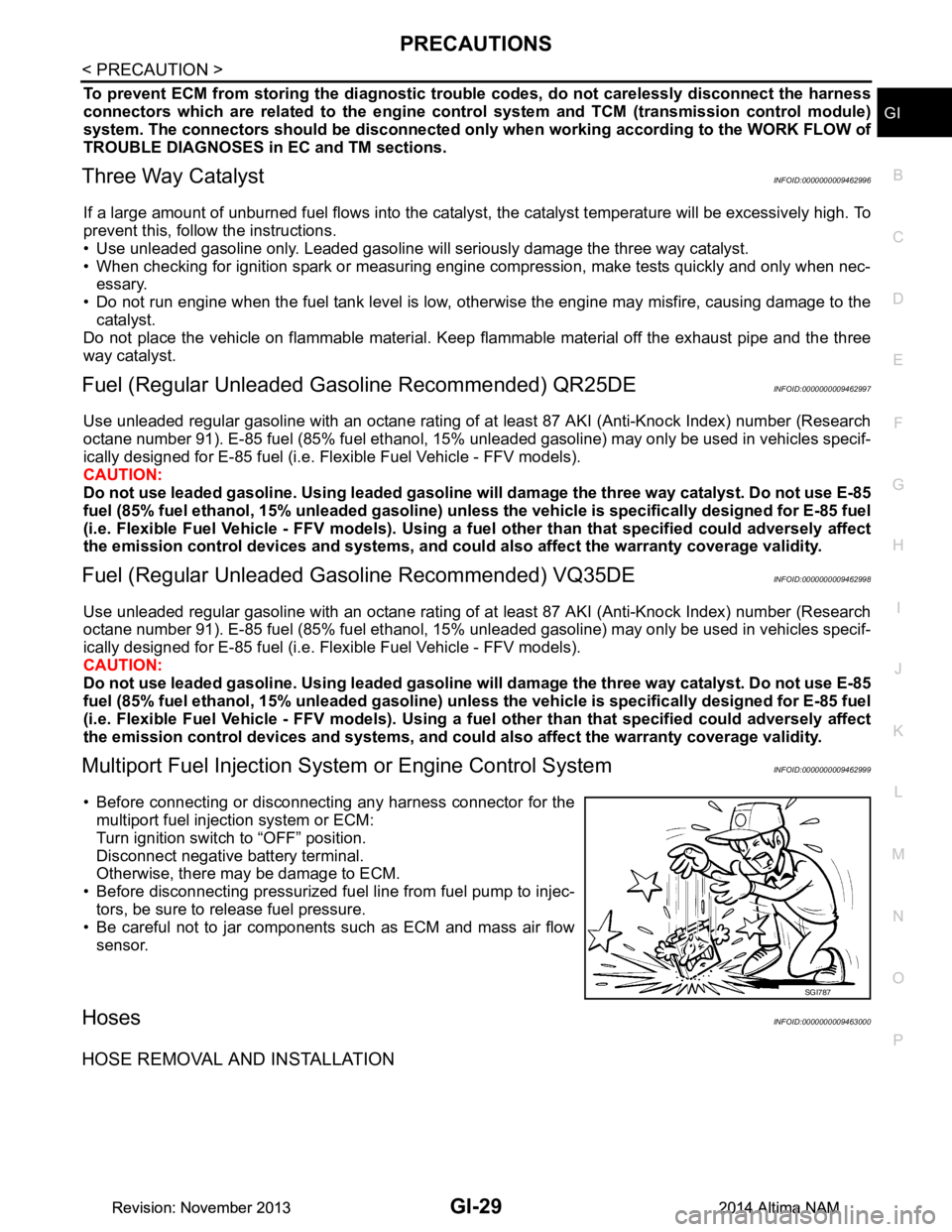
• Before disconnecting pressurized fuel line from fuel pump to injec-
tors, be sure to release fuel pressure.
• Be careful not to jar components such as ECM and mass air flow sensor.
HosesINFOID:0000000009463000
HOSE REMOVAL AND INSTALLATION
SGI787
Revision: November 20132014 Altima NAMRevision: November 20132014 Altima NAM
Page 2982 of 4801
![NISSAN TEANA 2014 Service Manual
LAN
SYSTEMLAN-33
< SYSTEM DESCRIPTION > [CAN]
C
D E
F
G H
I
J
K L
B
A
O P
N
Engine status signal T R R R R
Fuel consumption monitor signal T R R
Fuel filler cap warning display signal T R
Malfunc NISSAN TEANA 2014 Service Manual
LAN
SYSTEMLAN-33
< SYSTEM DESCRIPTION > [CAN]
C
D E
F
G H
I
J
K L
B
A
O P
N
Engine status signal T R R R R
Fuel consumption monitor signal T R R
Fuel filler cap warning display signal T R
Malfunc](/manual-img/5/57390/w960_57390-2981.png)
LAN
SYSTEMLAN-33
< SYSTEM DESCRIPTION > [CAN]
C
D E
F
G H
I
J
K L
B
A
O P
N
Engine status signal T R R R R
Fuel consumption monitor signal T R R
Fuel filler cap warning display signal T R
Malfunctioning indicator lamp signal TR
RT
Oil pressure warning lamp signal T R
Power generation command value
signal TR
Target throttle position signal T R
Wide open throttle position signal T R
EPS operation signal R T
Hydraulic pump electric power steer-
ing warning lamp signal TR
Detention switch signal T R R
Front wiper stop position signal T R
High beam status signal R T
Hood switch signal T R
Interlock/PNP switch signal RT
TR R
Low beam status signal R T
Oil pressure switch signal RT
TR R
Push-button ignition switch status
signal TR
Rear window defogger control signal R T
Sleep ready signal T R
Starter relay status signal T R
Steering lock unit status signal T R
Steering lock relay signal RT
TR
Current gear position signal T R R
CVT position indicator signal T R R
Input shaft revolution signal R T R R
Manual mode indicator signal T R R
N range signal T R
Output shaft revolution signal R T R R
O/D OFF indicator signal
*1TR R
P range signal T R R
Shift position signal T R R
Brake fluid level signal T R
Distance to empty signal T R
Fuel filler cap warning reset signal R T
Fuel level low warning signal T R
Fuel level sensor signal R T Signal name
ECM
EPS
IPDM-E TCM
M&A
STRG AV
AV M
HVAC ABS
BCM
Revision: November 20132014 Altima NAMRevision: November 20132014 Altima NAM
Page 3205 of 4801
ENGINE MAINTENANCE (QR25DE)MA-21
< PERIODIC MAINTENANCE >
C
D E
F
G H
I
J
K L
M B
MA
N
O A
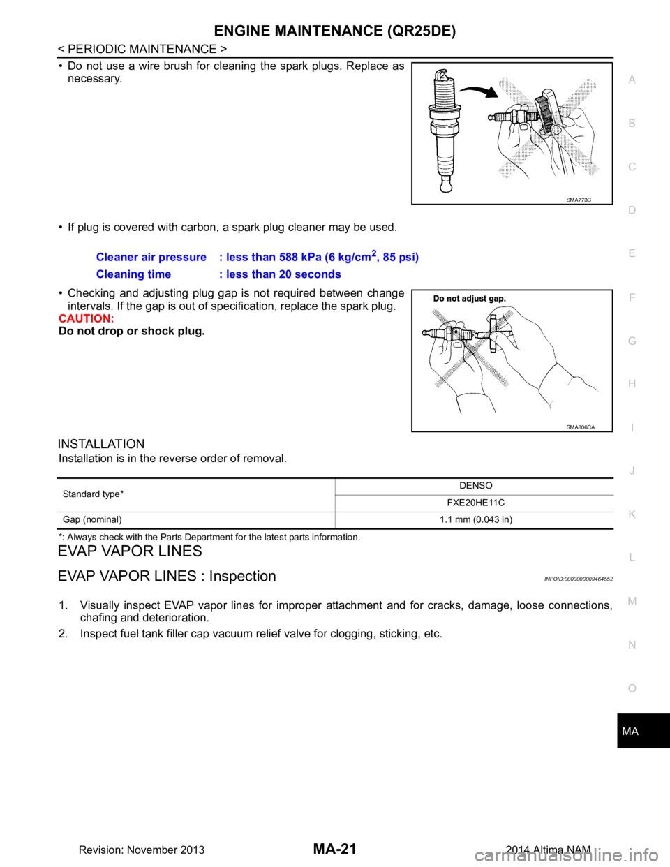
• Do not use a wire brush for cleaning the spark plugs. Replace as
necessary.
• If plug is covered with carbon, a spark plug cleaner may be used.
• Checking and adjusting plug gap is not required between change intervals. If the gap is out of s pecification, replace the spark plug.
CAUTION:
Do not drop or shock plug.
INSTALLATION
Installation is in the reverse order of removal.
*: Always check with the Parts Department for the latest parts information.
EVAP VAPOR LINES
EVAP VAPOR LINES : InspectionINFOID:0000000009464552
1. Visually inspect EVAP vapor lines for improper attachment and for cracks, damage, loose connections,
chafing and deterioration.
2. Inspect fuel tank filler cap vacuum relief valve for clogging, sticking, etc.
SMA773C
Cleaner air pressure : less than 588 kPa (6 kg/cm2, 85 psi)
Cleaning time : less than 20 seconds
SMA806CA
Standard type* DENSO
FXE20HE11C
Gap (nominal) 1.1 mm (0.043 in)
Revision: November 20132014 Altima NAM