2014 NISSAN TEANA ignition
[x] Cancel search: ignitionPage 3981 of 4801
SIDE CURTAIN AIR BAG MODULESR-19
< REMOVAL AND INSTALLATION >
C
D E
F
G
I
J
K L
M A
B
SR
N
O P
SIDE CURTAIN AIR BAG MODULE
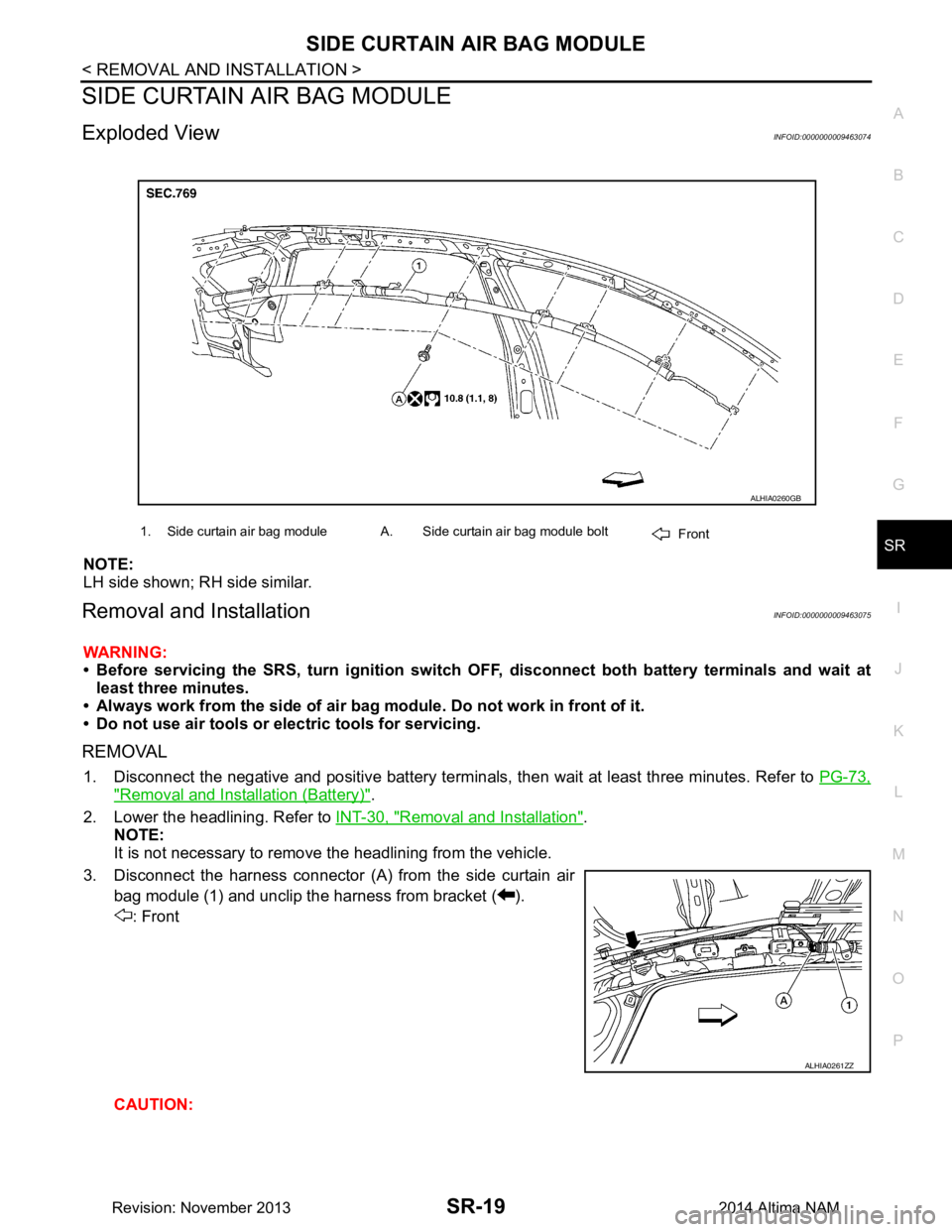
Exploded ViewINFOID:0000000009463074
NOTE:
LH side shown; RH side similar.
Removal and InstallationINFOID:0000000009463075
WARNING:
• Before servicing the SRS, turn ignition switch OFF, disconnect both battery terminals and wait at
least three minutes.
• Always work from the side of air bag module. Do not work in front of it.
• Do not use air tools or electric tools for servicing.
REMOVAL
1. Disconnect the negative and positive bat tery terminals, then wait at least three minutes. Refer to PG-73,
"Removal and Installation (Battery)".
2. Lower the headlining. Refer to INT-30, "Removal and Installation"
.
NOTE:
It is not necessary to remove the headlining from the vehicle.
3. Disconnect the harness connector (A) from the side curtain air bag module (1) and unclip the harness from bracket ( ).
: Front
CAUTION:
1. Side curtain air bag module A. Side curtain air bag module bolt Front
ALHIA0260GB
ALHIA0261ZZ
Revision: November 20132014 Altima NAM
Page 3985 of 4801
SIDE AIR BAG (SATELLITE) SENSOR
SR-23
< REMOVAL AND INSTALLATION >
C
D E
F
G
I
J
K L
M A
B
SR
N
O P
SIDE AIR BAG (S ATELLITE) SENSOR
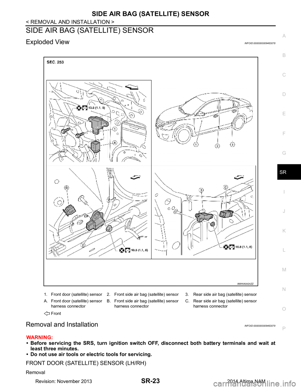
Exploded ViewINFOID:0000000009463078
Removal and InstallationINFOID:0000000009463079
WARNING:
• Before servicing the SRS, turn ignition switch OFF, disconnect both battery terminals and wait at
least three minutes.
• Do not use air tools or electric tools for servicing.
FRONT DOOR (SATELLITE) SENSOR (LH/RH)
Removal
1. Front door (satellite) sensor 2. Front side air bag (satellite) sensor 3. Rear side air bag (satellite) sensor
A. Front door (satellite) sensor harness connector B. Front side air bag (satellite) sensor
harness connector C. Rear side air bag (satellite) sensor
harness connector
Front
AWHIA0424ZZ
Revision: November 20132014 Altima NAM
Page 3996 of 4801

SRC-3
C
D E
F
G
I
J
K L
M A
B
SRC
N
O P
B142A IGNITION VOLTAGE ......................... ..104
Description .......................................................... ..104
DTC Logic .............................................................104
Diagnosis Procedure .............................................104
U1000 CAN COMM CIRCUIT ...........................106
Description .......................................................... ..106
DTC Logic .............................................................106
Diagnosis Procedure .............................................106
U1010 CONTROL UNIT (CAN) ........................107
Description .......................................................... ..107
DTC Logic .............................................................107
Diagnosis Procedure .............................................107
SYMPTOM DIAGNOSIS ............................108
SRS AIR BAG WARNING LAMP DOES NOT
TURN ON ......... ...............................................
108
AIR BAG Warning Lamp Does Not Turn On ....... ..108
SRS AIR BAG WARNING LAMP DOES NOT
TURN OFF ........ ...............................................
109
AIR BAG Warning Lamp Does Not Turn Off ....... ..109
SEAT BELT WARNING SYSTEM ..................110
Seat Belt Warning System Does Not Function ......110
Revision: November 20132014 Altima NAMRevision: November 20132014 Altima NAM
Page 3997 of 4801

SRC-4
< PRECAUTION >
PRECAUTIONS
PRECAUTION
PRECAUTIONS
Precaution for Supplemental Restraint System (SRS) "AIR BAG" and "SEAT BELT
PRE-TENSIONER"
INFOID:0000000009460702
The Supplemental Restraint System such as “A IR BAG” and “SEAT BELT PRE-TENSIONER”, used along
with a front seat belt, helps to reduce the risk or severi ty of injury to the driver and front passenger for certain
types of collision. Information necessary to service the system safely is included in the SR and SB section of
this Service Manual.
WARNING:
• To avoid rendering the SRS inopera tive, which could increase the risk of personal injury or death in
the event of a collision which would result in air bag inflation, all maintenance must be performed by
an authorized NISS AN/INFINITI dealer.
• Improper maintenance, including in correct removal and installation of the SRS, can lead to personal
injury caused by unintent ional activation of the system. For re moval of Spiral Cable and Air Bag
Module, see the SR section.
• Do not use electrical test equipmen t on any circuit related to the SRS unless instructed to in this
Service Manual. SRS wiring harn esses can be identified by yellow and/or orange harnesses or har-
ness connectors.
PRECAUTIONS WHEN USING POWER TOOLS (AIR OR ELECTRIC) AND HAMMERS
WARNING:
• When working near the Airbag Diagnosis Sensor Unit or other Airbag System sensors with the Igni-
tion ON or engine running, DO NOT use air or electri c power tools or strike near the sensor(s) with a
hammer. Heavy vibration could activate the sensor( s) and deploy the air bag(s), possibly causing
serious injury.
• When using air or electric power tools or hammers , always switch the Ignition OFF, disconnect the
battery and wait at least three minutes before performing any service.
Precaution for SRS "AIR BAG" and "S EAT BELT PRE-TENSIONER" Service
INFOID:0000000009460703
• Do not use electrical test equipment to check SRS ci rcuits unless instructed to in this Service Manual.
• Before servicing the SRS, turn ignition switch OFF, disconnect both battery cables and wait at least 3 min-
utes.
For approximately 3 minutes after the cables are removed, it is still possible for the air bag and seat belt pre-
tensioner to deploy. Therefore, do not work on any SR S connectors or wires until at least 3 minutes have
passed.
• The air bag diagnosis sensor unit must always be installed with the arrow mark “ ⇐” pointing toward the front
of the vehicle for proper operation. Also check air bag diagnosis sensor unit for cracks, deformities or rust
before installation and replace as required.
• The spiral cable must be aligned with the neutral position since its rotations are limited. Do not attempt to
turn steering wheel or column after removal of steering gear.
• Handle air bag module carefully. Always place driver and front passenger air bag modules with the pad side facing upward and seat mounted front side air bag m odule standing with the stud bolt side facing down.
• Conduct self-diagnosis to check entire SRS for proper function after replacing any components.
• After air bag inflates, the front instrument panel assembly should be replaced if damaged.
Revision: November 20132014 Altima NAMRevision: November 20132014 Altima NAM
Page 4004 of 4801
SYSTEMSRC-11
< SYSTEM DESCRIPTION >
C
D E
F
G
I
J
K L
M A
B
SRC
N
O P
SYSTEM
SRS AIR BAG SYSTEM
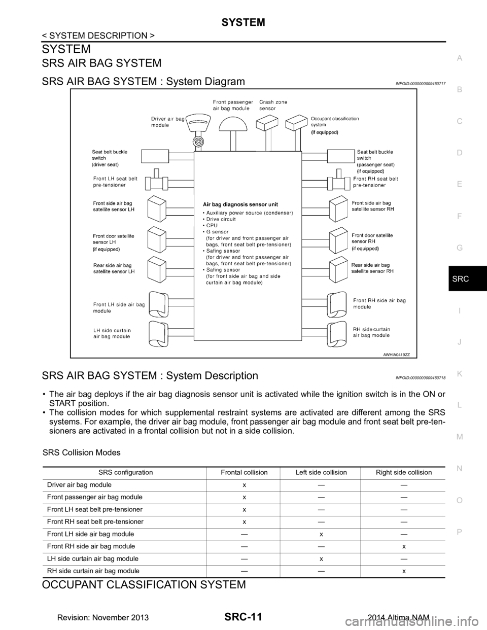
SRS AIR BAG SYSTEM : System DiagramINFOID:0000000009460717
SRS AIR BAG SYSTEM : System DescriptionINFOID:0000000009460718
• The air bag deploys if the air bag diagnosis sensor unit is activated while the ignition switch is in the ON or START position.
• The collision modes for which supplemental restrain t systems are activated are different among the SRS
systems. For example, the driver air bag module, front passenger air bag module and front seat belt pre-ten-
sioners are activated in a frontal collision but not in a side collision.
SRS Collision Modes
OCCUPANT CLASSIFICATION SYSTEM
AWHIA0419ZZ
SRS configuration Frontal collision Left side collision Right side collision
Driver air bag module x — —
Front passenger air bag module x — —
Front LH seat belt pre-tensioner x — —
Front RH seat belt pre-tensioner x — —
Front LH side air bag module — x —
Front RH side air bag module — — x
LH side curtain air bag module — x —
RH side curtain air bag module — — x
Revision: November 20132014 Altima NAMRevision: November 20132014 Altima NAM
Page 4007 of 4801
SRC-14
< SYSTEM DESCRIPTION >
SYSTEM
SEAT BELT WARNING LAMP SYSTEM : System Description
INFOID:0000000009460722
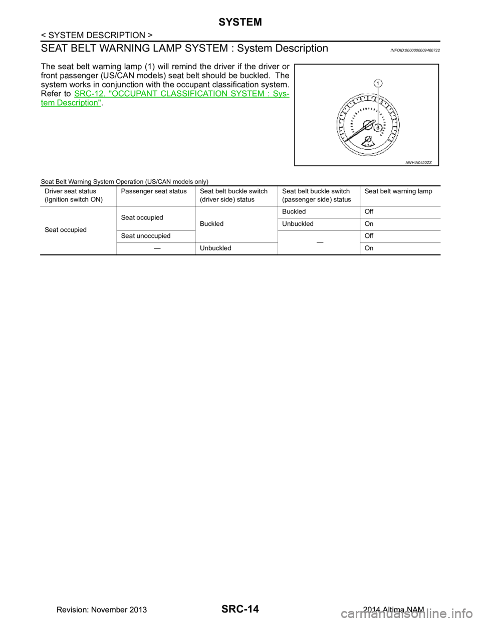
The seat belt warning lamp (1) will remind the driver if the driver or
front passenger (US/CAN models) seat belt should be buckled. The
system works in conjunction with t he occupant classification system.
Refer to SRC-12, "OCCUPANT CLASSIFI CATION SYSTEM : Sys-
tem Description".
Seat Belt Warning System Operation (US/CAN models only)
AWHIA0422ZZ
Driver seat status
(Ignition switch ON) Passenger seat status Seat belt buckle switch
(driver side) status Seat belt buckle switch
(passenger side) status Seat belt warning lamp
Seat occupied Seat occupied
Buckled Buckled Off
Unbuckled On
Seat unoccupied —Off
— Unbuckled On
Revision: November 20132014 Altima NAMRevision: November 20132014 Altima NAM
Page 4008 of 4801
DIAGNOSIS SYSTEM (AIR BAG)SRC-15
< SYSTEM DESCRIPTION >
C
D E
F
G
I
J
K L
M A
B
SRC
N
O P
DIAGNOSIS SYSTEM (AIR BAG)
Diagnosis DescriptionINFOID:0000000009460723
CAUTION:
• Do not use electrical test equipment on any circui t related to the SRS unless instructed to do so in
this Service Manual. SRS wiring harnesses can be id entified by yellow and/or orange harness con-
nectors.
• Do not attempt to repair, splice or modify SRS wiring harnesses. If a harness is damaged, replace it
with a new one.
• Keep ground connections clean.
HOW TO PERFORM TROUBLE DIAGNOSES FOR QUICK AND ACCURATE REPAIR
1. Obtain information about the symptom.
- WHAT - vehicle model
- WHEN - date, frequencies
- WHERE - road conditions
- HOW - operating conditions, symptoms, passengers
2. Perform Preliminary Check.
-Battery
- Fuses
- Harness connections
DIAGNOSIS METHODS
SRS self-diagnosis results can be read by using the AIR BAG warning lamp or CONSULT.
The User Mode is for the customer (driver). This m ode warns the driver of a system malfunction through the
AIR BAG warning lamp.
The Diagnosis Mode is for the technician. This mode hel ps the technician locate the malfunctioning circuit or
part.
SRS Operation CheckINFOID:0000000009460724
USER MODE
1. Turn the ignition switch from OFF to ON and check that the air bag warning lamp flashes.
2. Compare the flashing pattern with the examples in the table.
User Mode Diagnosis Mode Display type
AIR BAG warning lamp X X ON/OFF CONSULT — X Monitoring
BF-1845D
Revision: November 20132014 Altima NAMRevision: November 20132014 Altima NAM
Page 4010 of 4801
DIAGNOSIS SYSTEM (AIR BAG)SRC-17
< SYSTEM DESCRIPTION >
C
D E
F
G
I
J
K L
M A
B
SRC
N
O P
Trouble Diagnosis without CONSULTINFOID:0000000009460726
DIAGNOSIS MODE
NOTE:
Diagnosis Mode can not be entered if a malfunction is not detected in User Mode.
1. Turn ignition switch ON.
2. After AIR BAG warning lamp lights for 7 seconds, turn ignition switch OFF within 1 second.
3. Wait more than 3 seconds.
4. Repeat steps 1 to 3 two more times (3 times total).
5. Turn ignition switch ON.
SRS is now in Diagnosis Mode. Refer to SRC-23, "Flash Code Index"
.
SRS History CheckINFOID:0000000009460727
SRS HISTORY CHECK
1. Check repair history of the SRS. If no repairs have been made, perform SRC-15, "SRS Operation
Check". If repairs have been made, GO TO step 2.
2. Erase "SELF-DIAG [PAST]" after repair. Refer to SRC-17, "SRS Final Check"
.
SRS Final CheckINFOID:0000000009460728
DIAGNOSIS MODE
1. Connect CONSULT.
2. Confirm that zero point reset of OCS is complete.
3. If no DTCs are detected on “SELF- DIAG RESULTS [CURRENT]”, repair of SRS is completed. Go to step
4.
If any DTCs are detected on “SEL F-DIAG RESULTS [CURRENT]”, t he malfunction has not been repaired
completely or another malfunction is being detected. Perform SRS Operation Check again. Refer to
SRC-15, "SRS Operation Check"
.
4. Touch “ERASE”. NOTE:
Touching “ERASE” will clear the SRS memory of the malfunction (“SELF-DIAG [PAST]”). If “SELF-
DIAG [PAST]” is not erased, User Mode may s how the previous system malfunction even if the
malfunction has been repaired completely.
5. Check that no malfunction is detected in “SELF-DIAG [PAST]”.
6. Exit Diagnosis Mode and disconnect the CONSULT.
7. Perform SRS Operation Check. Refer to SRC-15, "SRS Operation Check"
.
CONSULT Function (AIR BAG)INFOID:0000000009460729
CAUTION:
After disconnecting the CONSULT vehicle interface (VI) from the data link connector, the ignition must
be cycled OFF → ON (for at least 5 seconds) → OFF. If this step is not performed, the BCM may not go
to ”sleep mode”, potentiall y causing a discharged battery and a no-start condition.
CONSULT can display each diagnostic item using the diagnostic test modes shown following.
Diagnostic Test Mode Diagnostic Item Description
Self Diagnostic Result SEL F-DIAG RESULT [CURRENT]A current Self-diagnosis result (also indicated by the number of
warning lamp flashes in the Diagnosis mode) is displayed on the
CONSULT screen in real time. This refers to a malfunctioning part
requiring repairs.
Data Monitor DATA MONITOR Displays air bag diagnosis sensor unit input/output data in real time.
Ecu Identification ECU DISCRIMINATED NO. Air bag diagnosis sensor unit ECU discriminated number (identifica-
tion number) or part number is displayed. Air bag diagnosis sensor
unit has individual ECU discriminated number (identification num-
ber) or part number based on model and equipment.
Trouble Diagnostic Record TROUBLE DIAG RECORD [PAST] With TROUBLE DIAG RECORD, diagnosis results previously
erased by a reset operation can be displayed on the CONSULT
screen.
Revision: November 20132014 Altima NAMRevision: November 20132014 Altima NAM