2014 NISSAN TEANA ignition
[x] Cancel search: ignitionPage 3943 of 4801

SEC-118
< DTC/CIRCUIT DIAGNOSIS >
B2617 STARTER RELAY CIRCUIT
B2617 STARTER RELAY CIRCUIT
DescriptionINFOID:0000000009461176
Located in IPDM E/R, it runs the starter motor. The starter relay is turned ON by the BCM when the ignition
switch is in START position. IPDM E/R transmits t he starter relay ON signal to BCM via CAN communication.
DTC LogicINFOID:0000000009461177
DTC DETECTION LOGIC
NOTE:
• If DTC B2617 is displayed with DTC U1000, first perform the trouble diagnosis for DTC U1000. Refer to
BCS-68, "DTC Logic"
.
• If DTC B2617 is displayed with DTC U1010, first perform the trouble diagnosis for DTC U1010. Refer to BCS-69, "DTC Logic"
.
DTC CONFIRMATION PROCEDURE
1.PERFORM DTC CONFIRMATION PROCEDURE
1. Turn ignition switch ON under the following conditions and wait for at least 1 second.
- CVT selector lever is in the P (Park) position.
- Do not depress the brake pedal.
2. Check Self-Diagnostic Result with CONSULT.
Is DTC detected?
YES >> Refer to SEC-118, "Diagnosis Procedure".
NO >> Inspection End.
Diagnosis ProcedureINFOID:0000000009461178
Regarding Wiring Diagram information, refer to SEC-29, "Wiring Diagram".
1.CHECK STARTER RELAY
1. Turn ignition switch ON.
2. Check voltage between BCM harness connector and ground under the following condition.
Is the measurement value within the specification.
YES >> GO TO 3.
NO >> GO TO 2.
2.CHECK STARTER RELAY CIRCUIT
DTC No. Trouble diagnosis
name DTC detecting condition Possible cause
B2617 STARTER RELAY
CIRCUIT • An immediate operation of starter relay is re-
quested by BCM, but there is no response for
more than 1 second
• BCM is not commanding starter relay activation, but BCM detects starter relay output is active • Harness or connectors
(Starter relay circuit is open or short-
ed.)
• IPDM E/R
•BCM
BCM Ground Condition Voltage (V)
Connector Terminal
M18 62 Ground Ignition switch cranking 0
Ignition switch ON (Park or Neutral) Battery voltage
Other than above 0
Revision: November 20132014 Altima NAMRevision: November 20132014 Altima NAM
Page 3944 of 4801

B2617 STARTER RELAY CIRCUITSEC-119
< DTC/CIRCUIT DIAGNOSIS >
C
D E
F
G H
I
J
L
M A
B
SEC
N
O P
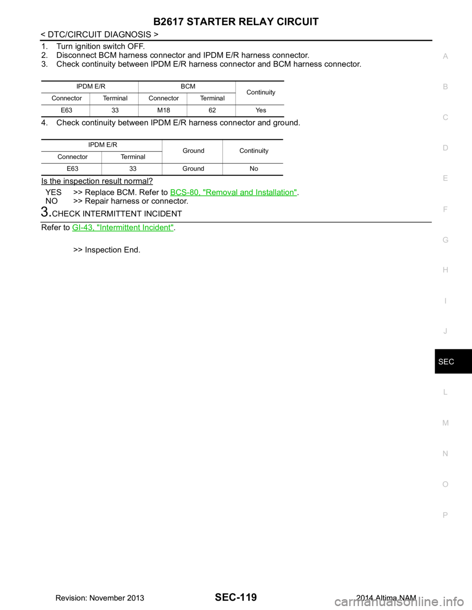
1. Turn ignition switch OFF.
2. Disconnect BCM harness connector and IPDM E/R harness connector.
3. Check continuity between IPDM E/R harness connector and BCM harness connector.
4. Check continuity between IPDM E/R harness connector and ground.
Is the inspection result normal?
YES >> Replace BCM. Refer to BCS-80, "Removal and Installation".
NO >> Repair harness or connector.
3.CHECK INTERMITTENT INCIDENT
Refer to GI-43, "Intermittent Incident"
.
>> Inspection End.
IPDM E/R BCM Continuity
Connector Terminal Connector Terminal
E63 33 M18 62 Yes
IPDM E/R Ground Continuity
Connector Terminal
E63 33 Ground No
Revision: November 20132014 Altima NAMRevision: November 20132014 Altima NAM
Page 3945 of 4801

SEC-120
< DTC/CIRCUIT DIAGNOSIS >
B261E VEHICLE TYPE
B261E VEHICLE TYPE
DescriptionINFOID:0000000009461179
There are two types of vehicles.
•HEV
• Conventional
DTC LogicINFOID:0000000009461180
DTC DETECTION LOGIC
NOTE:
• If DTC B261E is displayed with DTC U1000, first perform the trouble diagnosis for DTC U1000. Refer to
BCS-68, "DTC Logic"
.
• If DTC B261E is displayed with DTC U1010, first perform the trouble diagnosis for DTC U1010. Refer to
BCS-69, "DTC Logic"
.
DTC CONFIRMATION PROCEDURE
1.PERFORM DTC CONFIRMATION PROCEDURE
1. Turn ignition switch ON under the following conditions.
- Shift selector lever is in the P (Park) or N (Neutral) position
- Do not depress brake pedal
2. Check Self-Diagnostic Result using CONSULT.
Is DTC detected?
YES >> GO TO SEC-120, "Diagnosis Procedure".
NO >> Inspection End.
Diagnosis ProcedureINFOID:0000000009461181
1.INSPECTION START
1. Turn ignition switch ON.
2. Check Self-diagnostic result using CONSULT.
3. Touch ERASE.
4. Perform DTC Confirmation Procedure. Refer to SEC-120, "DTC Logic"
.
Is the 1st trip DTC B261E displayed again?
YES >> GO TO 2.
NO >> Inspection End.
2.PERFORM BCM CONFIGURATION.
Perform the BCM configuration. Refer to BCS-65, "CONFIGURATION (BCM) : Work Procedure"
.
>> GO TO 3.
3.INSPECTION START
1. Turn ignition switch ON.
2. Check Self-diagnostic result using CONSULT.
3. Touch ERASE.
4. Perform DTC Confirmation Procedure. Refer to SEC-120, "DTC Logic"
.
Is the 1st trip DTC B261E displayed again?
YES >> GO TO 4.
NO >> Inspection End.
DTC No. Trouble diagnosis name DTC detecting condition Possible cause
B261E VEHICLE TYPE Difference of BCM configuration. • BCM mis-configuration
• Wrong ECM installed
Revision: November 20132014 Altima NAMRevision: November 20132014 Altima NAM
Page 3948 of 4801

POWER SUPPLY AND GROUND CIRCUITSEC-123
< DTC/CIRCUIT DIAGNOSIS >
C
D E
F
G H
I
J
L
M A
B
SEC
N
O P
POWER SUPPLY AND GROUND CIRCUIT
Diagnosis ProcedureINFOID:0000000009956233
Regarding Wiring Diagram information, refer to PCS-21, "Wiring Diagram".
1. CHECK FUSIBLE LINKS
Check that the following fusible links are not blown.
Is the fusible link blown?
YES >> Replace the blown fusible link after repairing the affected circuit.
NO >> GO TO 2
2. CHECK POWER SUPPLY CIRCUIT
1. Disconnect IPDM E/R connectors E16 and E17.
2. Check voltage between IPDM E/R connectors and ground.
Is the inspection result normal?
YES >> GO TO 3
NO >> Repair or replace harness or connectors.
3. CHECK GROUND CIRCUIT
1. Disconnect IPDM E/R connectors E18 and E63.
2. Check continuity between IPDM E/R connectors and ground.
Is the inspection result normal?
YES >> Inspection End.
NO >> Repair or replace harness or connectors.
Terminal No. Signal name Fusible link No.
1 Fusible link main E (80A)
2 Fusible link IPDM E/R A (250A), C (80A)
3 Fusible link ignition switch A (250A), B (100A), M (40A)
IPDM E/R GroundVol tag e
(Approx.)
Connector Terminal
E16 1
— Battery voltage
2
E17 3
IPDM E/R Ground Continuity
Connector Terminal
E18 7 —Yes
E63 41
Revision: November 20132014 Altima NAMRevision: November 20132014 Altima NAM
Page 3950 of 4801

HOOD SWITCHSEC-125
< DTC/CIRCUIT DIAGNOSIS >
C
D E
F
G H
I
J
L
M A
B
SEC
N
O P
HOOD SWITCH
Component Function CheckINFOID:0000000009461186
1.CHECK FUNCTION
1. Select HOOD SW in Data Monito r mode of IPDM E/R using CONSULT.
2. Check HOOD SW indication under the following condition.
Is the indication normal?
YES >> Hood switch is OK.
NO >> Go to SEC-125, "Diagnosis Procedure"
.
Diagnosis ProcedureINFOID:0000000009461187
Regarding Wiring Diagram information, refer to SEC-50, "Wiring Diagram".
1.CHECK HOOD SWITCH SIGNAL CIRCUITS
1. Turn ignition switch OFF.
2. Disconnect hood switch connector.
3. Check voltage between hood switch harness connector and ground.
Is the inspection result normal?
YES >> GO TO 3.
NO >> GO TO 2.
2.CHECK HOOD SWITCH SIGNAL CIRCUITS
1. Disconnect IPDM E/R connector.
2. Check continuity between IPDM E/R har ness connector and hood switch harness connector.
3. Check continuity between IPDM E/R harness connector and ground.
Is the inspection result normal?
YES >> Replace IPDM E/R. Refer to PCS-32, "Removal and Installation".
NO >> Repair or replace harness.
Monitor item Condition Indication
HOOD SW Hood Open ON
Close OFF
(+) (–) Voltage (V)
IPDM E/R
Connector Terminal
E201 94
Ground Battery voltage
96
IPDM E/R Hood switch Continuity
Connector Terminal Connector Terminal
E201 94
E248 1
Ye s
96 2
IPDM E/R GroundContinuity
Connector Terminal
E201 94
No
96
Revision: November 20132014 Altima NAMRevision: November 20132014 Altima NAM
Page 3951 of 4801

SEC-126
< DTC/CIRCUIT DIAGNOSIS >
HOOD SWITCH
3.CHECK HOOD SWITCH GROUND CIRCUIT
Check continuity between hood switch harness connector and ground.
Is the inspection result normal?
YES >> GO TO 4.
NO >> Repair or replace harness.
4.CHECK HOOD SWITCH
Refer to SEC-126, "Component Inspection"
.
Is the inspection result normal?
YES >> GO TO 5.
NO >> Replace hood switch. Refer to DLK-176, "HOOD LOCK CONTROL : Removal and Installation"
.
5.CHECK INTERMITTENT INCIDENT
Refer to GI-43, "Intermittent Incident"
.
>> Inspection End.
Component InspectionINFOID:0000000009461188
1.CHECK HOOD SWITCH
1. Turn ignition switch OFF.
2. Disconnect hood switch connector.
3. Check continuity between hood switch terminals.
Is the inspection result normal?
YES >> Inspection End.
NO >> Replace hood switch. Refer to DLK-176, "HOOD LOCK CONTROL : Removal and Installation"
.
Hood switch
GroundContinuity
Connector Terminal
E205 3 Yes
Hood switch Condition Continuity
Te r m i n a l
1 3 Hood switch Press No
Release Yes
2 Press No
Release Yes
Revision: November 20132014 Altima NAMRevision: November 20132014 Altima NAM
Page 3952 of 4801

SECURITY INDICATOR LAMPSEC-127
< DTC/CIRCUIT DIAGNOSIS >
C
D E
F
G H
I
J
L
M A
B
SEC
N
O P
SECURITY INDICATOR LAMP
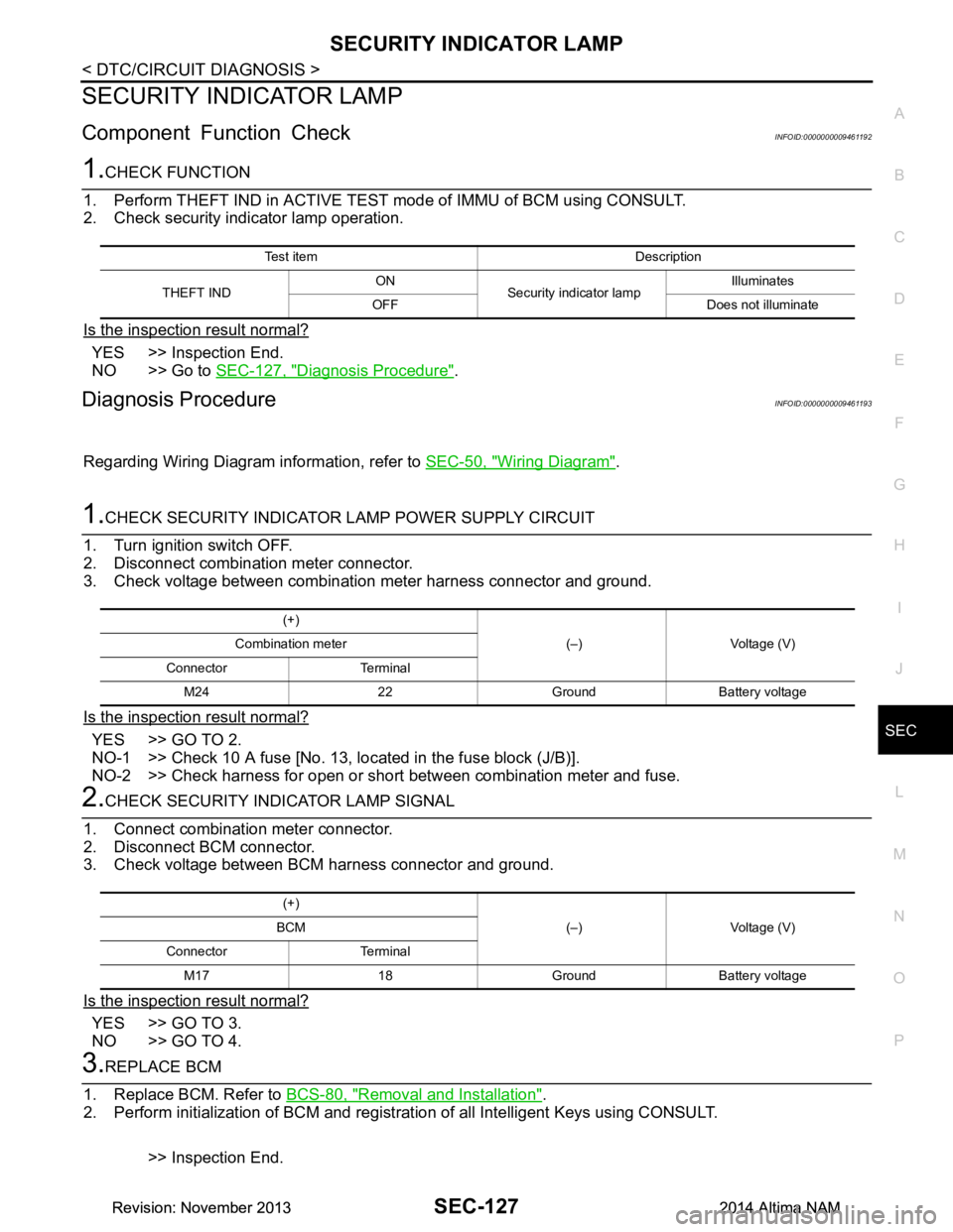
Component Function CheckINFOID:0000000009461192
1.CHECK FUNCTION
1. Perform THEFT IND in ACTIVE TEST mode of IMMU of BCM using CONSULT.
2. Check security indicator lamp operation.
Is the inspection result normal?
YES >> Inspection End.
NO >> Go to SEC-127, "Diagnosis Procedure"
.
Diagnosis ProcedureINFOID:0000000009461193
Regarding Wiring Diagram information, refer to SEC-50, "Wiring Diagram".
1.CHECK SECURITY INDICATOR LAMP POWER SUPPLY CIRCUIT
1. Turn ignition switch OFF.
2. Disconnect combination meter connector.
3. Check voltage between combination meter harness connector and ground.
Is the inspection result normal?
YES >> GO TO 2.
NO-1 >> Check 10 A fuse [No. 13, lo cated in the fuse block (J/B)].
NO-2 >> Check harness for open or short between combination meter and fuse.
2.CHECK SECURITY INDICATOR LAMP SIGNAL
1. Connect combination meter connector.
2. Disconnect BCM connector.
3. Check voltage between BCM harness connector and ground.
Is the inspection result normal?
YES >> GO TO 3.
NO >> GO TO 4.
3.REPLACE BCM
1. Replace BCM. Refer to BCS-80, "Removal and Installation"
.
2. Perform initialization of BCM and registration of all Intelligent Keys using CONSULT.
>> Inspection End.
Test item Description
THEFT IND ON
Security indicator lamp Illuminates
OFF Does not illuminate
(+) (–) Voltage (V)
Combination meter
Connector Terminal M24 22 Ground Battery voltage
(+) (–) Voltage (V)
BCM
Connector Terminal M17 18 Ground Battery voltage
Revision: November 20132014 Altima NAMRevision: November 20132014 Altima NAM
Page 3954 of 4801

ENGINE DOES NOT START WHEN INTELLIGENT KEY IS INSIDE OF VEHICLE
SEC-129
< SYMPTOM DIAGNOSIS >
C
D E
F
G H
I
J
L
M A
B
SEC
N
O P
SYMPTOM DIAGNOSIS
ENGINE DOES NOT START WHEN IN TELLIGENT KEY IS INSIDE OF VE-
HICLE
DescriptionINFOID:0000000009461194
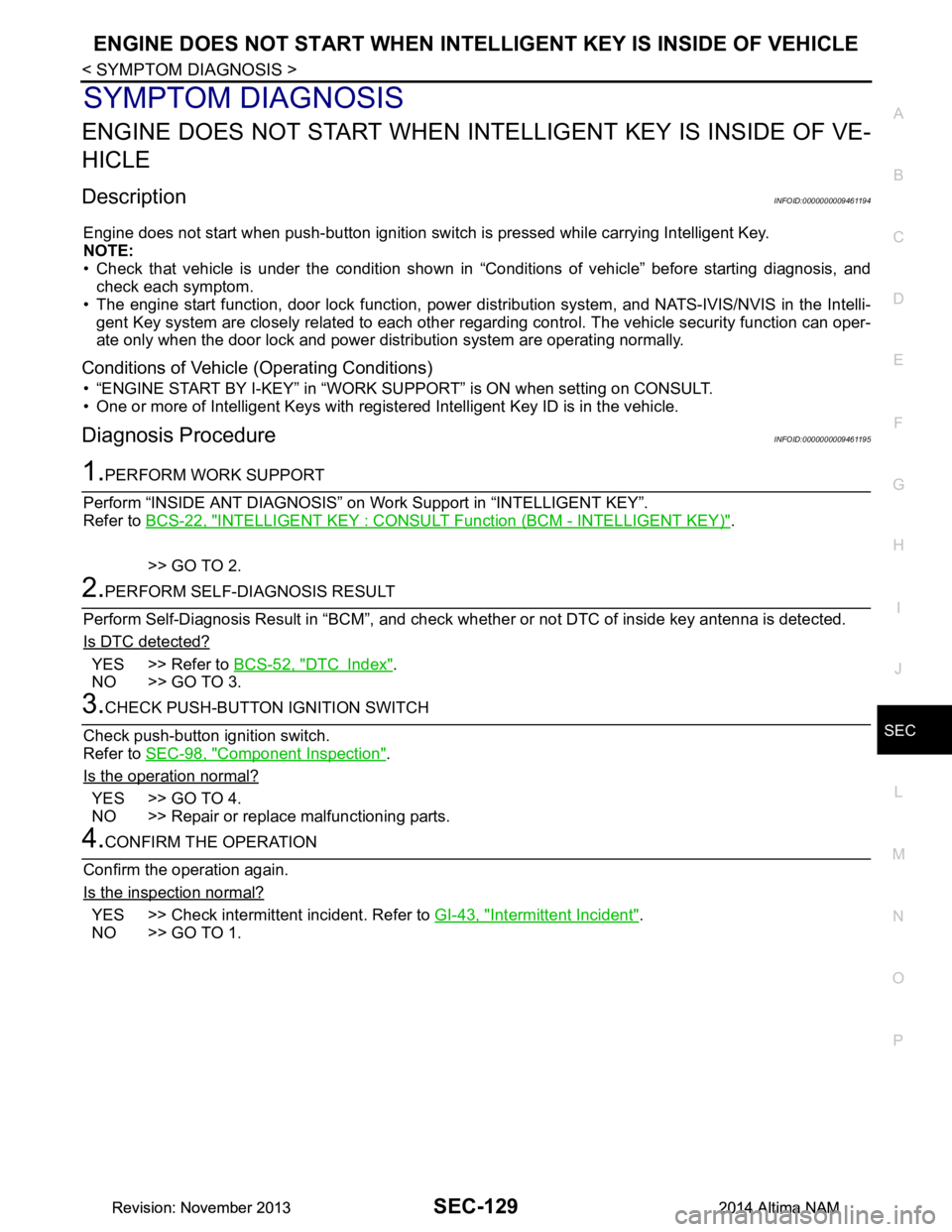
Engine does not start when push-button ignition swit ch is pressed while carrying Intelligent Key.
NOTE:
• Check that vehicle is under the condition shown in “Conditions of vehicle” before starting diagnosis, and
check each symptom.
• The engine start function, door lock function, power dist ribution system, and NATS-IVIS/NVIS in the Intelli-
gent Key system are closely related to each other regar ding control. The vehicle security function can oper-
ate only when the door lock and power distribution system are operating normally.
Conditions of Vehicle (Operating Conditions)
• “ENGINE START BY I-KEY” in “WORK SUPPORT” is ON when setting on CONSULT.
• One or more of Intelligent Keys with registered Intelligent Key ID is in the vehicle.
Diagnosis ProcedureINFOID:0000000009461195
1.PERFORM WORK SUPPORT
Perform “INSIDE ANT DIAGNOSIS” on Wo rk Support in “INTELLIGENT KEY”.
Refer to BCS-22, "INTELLIGENT KEY : CONSUL T Function (BCM - INTELLIGENT KEY)"
.
>> GO TO 2.
2.PERFORM SELF-DIAGNOSIS RESULT
Perform Self-Diagnosis Result in “BCM”, and check whether or not DTC of inside key antenna is detected.
Is DTC detected?
YES >> Refer to BCS-52, "DTC Index".
NO >> GO TO 3.
3.CHECK PUSH-BUTTON IGNITION SWITCH
Check push-button ignition switch.
Refer to SEC-98, "Component Inspection"
.
Is the operation normal?
YES >> GO TO 4.
NO >> Repair or replace malfunctioning parts.
4.CONFIRM THE OPERATION
Confirm the operation again.
Is the inspection normal?
YES >> Check intermittent incident. Refer to GI-43, "Intermittent Incident".
NO >> GO TO 1.
Revision: November 20132014 Altima NAMRevision: November 20132014 Altima NAM