2014 NISSAN TEANA coolant temperature
[x] Cancel search: coolant temperaturePage 3159 of 4801
![NISSAN TEANA 2014 Service Manual
ENGINE OILLU-9
< PERIODIC MAINTENANCE > [QR25DE]
C
D E
F
G H
I
J
K L
M A
LU
NP
O
PERIODIC MAINTENANCE
ENGINE OIL
InspectionINFOID:0000000009461028
OIL LEVEL
• Before starting the engine, check the NISSAN TEANA 2014 Service Manual
ENGINE OILLU-9
< PERIODIC MAINTENANCE > [QR25DE]
C
D E
F
G H
I
J
K L
M A
LU
NP
O
PERIODIC MAINTENANCE
ENGINE OIL
InspectionINFOID:0000000009461028
OIL LEVEL
• Before starting the engine, check the](/manual-img/5/57390/w960_57390-3158.png)
ENGINE OILLU-9
< PERIODIC MAINTENANCE > [QR25DE]
C
D E
F
G H
I
J
K L
M A
LU
NP
O
PERIODIC MAINTENANCE
ENGINE OIL
InspectionINFOID:0000000009461028
OIL LEVEL
• Before starting the engine, check the oil level. If t
he engine is already started, stop it and allow 10 minutes
before checking.
• Check that the oil level is within the range (A) on the oil level
gauge.
• If it is out of range, add oil as necessary.
ENGINE OIL APPEARANCE
• Check engine oil for white milky appearance or excessive contamination.
• If engine oil becomes milky, it is highly probable t hat it is contaminated with engine coolant. Repair or
replace damaged parts.
OIL LEAKAGE
Check for oil leakage around the following areas:
•Oil pan
• Oil pan drain plug
• Oil pressure switch
• Oil filter
• Oil cooler
• Valve timing control cover and valve timing control solenoid valve
• Front cover
• Mating surface between cylinder block and cylinder head
• Mating surface between cylinder head and rocker cover
• Crankshaft oil seal (front and rear)
OIL PRESSURE CHECK
WARNING:
• Be careful not to burn yoursel f, as engine oil may be hot.
• Put the CVT shift selector in the Park "P" position.
1. Check engine oil level. Refer to OIL LEVEL.
2. Remove fender protector side cover (RH). Refer to EXT-26, "FENDER PROTECTOR : Exploded View"
.
3. Disconnect oil pressure switch harness connector at oil pressure switch. Remove oil pressure switch and install Tools.
CAUTION:
Do not drop or shock oil pressure switch.
4. Start engine and warm it up to normal operating temperature.
5. Check oil pressure with engine running under no-load, using Tool. NOTE:
JPBIA1497ZZ
Tool numbers : ST25051001 (J-25695-1)
: ST25052000 (J-25695-2)
WBIA0571E
Revision: November 20132014 Altima NAM
Page 3175 of 4801
![NISSAN TEANA 2014 Service Manual
ENGINE OILLU-25
< PERIODIC MAINTENANCE > [VQ35DE]
C
D E
F
G H
I
J
K L
M A
LU
NP
O
PERIODIC MAINTENANCE
ENGINE OIL
InspectionINFOID:0000000009461048
OIL LEVEL
NOTE:
• Before starting the engine, c NISSAN TEANA 2014 Service Manual
ENGINE OILLU-25
< PERIODIC MAINTENANCE > [VQ35DE]
C
D E
F
G H
I
J
K L
M A
LU
NP
O
PERIODIC MAINTENANCE
ENGINE OIL
InspectionINFOID:0000000009461048
OIL LEVEL
NOTE:
• Before starting the engine, c](/manual-img/5/57390/w960_57390-3174.png)
ENGINE OILLU-25
< PERIODIC MAINTENANCE > [VQ35DE]
C
D E
F
G H
I
J
K L
M A
LU
NP
O
PERIODIC MAINTENANCE
ENGINE OIL
InspectionINFOID:0000000009461048
OIL LEVEL
NOTE:
• Before starting the engine, check the oil level. If the engine is already started, stop it and a llow 10 minutes before checking.
• Check that the oil level is within the range as indicated on the oil level gauge.
• If it is out of range, add oil as necessary.
ENGINE OIL APPEARANCE
• Check engine oil for white milky appearance or excessive contamination.
• If engine oil becomes milky, it is highly probable t hat it is contaminated with engine coolant. Repair or
replace damaged parts.
OIL LEAKAGE
Check for oil leakage around the following areas:
•Oil pan
• Oil pan drain plug
• Oil pressure switch
• Oil filter
• Oil cooler
• Intake valve timing control cover and intake valve timing control solenoid valve
• Front cover
• Mating surface between cylinder block and cylinder head
• Mating surface between cylinder head and rocker cover
• Crankshaft oil seal (front and rear)
OIL PRESSURE CHECK
WARNING:
• Be careful not to burn yoursel f, as engine oil may be hot.
• Put the CVT shift selector in the Park “P” position.
1. Check the oil level.
2. Remove fender protector side cover (RH). Refer to EXT-26, "FENDER PROTECTOR : Exploded View"
.
3. Disconnect oil pressure switch harness connector at the oil pressure switch. Remove oil pressure switch and install Tools.
CAUTION:
Do not drop or shock oil pressure switch.
4. Start the engine and warm it up to normal operating temperature.
5. Check oil pressure with engine running under no-load, using Tool. NOTE:
• When engine oil temperature is low, engine oil pressure becomes high.
JMA122D
Tool numbers : ST25051001 (J-25695-1)
: ST25052000 (J-25695-2)
WBIA0571E
Revision: November 20132014 Altima NAM
Page 3190 of 4801

MA-6
< PERIODIC MAINTENANCE >
GENERAL MAINTENANCE
UNDER THE HOOD AND VEHICLE
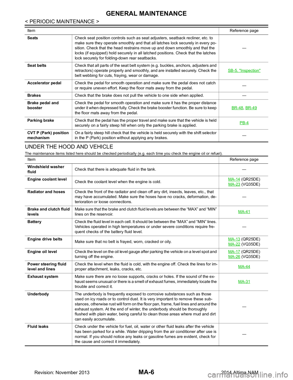
The maintenance items listed here should be checked periodically (e.g. each time you check the engine oil or refuel).
SeatsCheck seat position controls such as seat adjusters, seatback recliner, etc. to
make sure they operate smoothly and that all latches lock securely in every po-
sition. Check that the head restrains move up and down smoothly and that the
locks (if equipped) hold securely in all latched positions. Check that the latches
lock securely for folding-down rear seatbacks. —
Seat belts Check that all parts of the seat belt system (e.g. buckles, anchors, adjusters and
retractors) operate properly and smoothly, and are installed securely. Check the
belt webbing for cuts, fraying, wear or damage. SB-5, "Inspection"
Accelerator pedal
Check the pedal for smooth operation and make sure the pedal does not catch
or require uneven effort. Keep the floor mats away from the pedal. —
Brakes Check that the brake does not pull the vehicle to one side when applied. —
Brake pedal and
booster Check the pedal for smooth operation and make sure it has the proper distance
under it when depressed fully. Check the brake booster function. Be sure to keep
the floor mats away from the pedal. BR-48
,
BR-49
Parking brake Check that the pedal has the proper travel and make sure that the vehicle is held
securely on a fairly steep hill when only the parking brake is applied. PB-4
CVT P (Park) position
mechanism On a fairly steep hill check that the vehicle is held securely with the shift selector
in the P (Park) position without applying any brakes. —
Item
Reference page
ItemReference page
Windshield washer
fluid Check that there is adequate fluid in the tank. —
Engine coolant level Check the coolant level when the engine is cold. MA-14
(QR25DE)
MA-23
(VQ35DE)
Radiator and hoses Check the front of the radiator and clean off any dirt, insects, leaves, etc., that
may have accumulated. Make sure the hoses have no cracks, deformation, de-
terioration or loose connections. —
Brake and clutch fluid
levels Make sure that the brake and clutch fluid levels are between the “MAX” and “MIN”
lines on the reservoir. MA-41
Battery
Check the fluid level in each cell. It should be between the “MAX” and “MIN” lines.
Vehicles operated in high temperatures or under severe conditions require fre-
quent checks of the battery fluid level. —
Engine drive belts Make sure that no belt is frayed, worn, cracked or oily. MA-13
(QR25DE)
MA-22
(VQ35DE)
Engine oil level Check the level on the oil level gauge after parking the vehicle on a level spot and
turning off the engine. MA-17
(QR25DE)
MA-26
(VQ35DE)
Power steering fluid
level and lines Check the level when the fluid is cold, with the engine off. Check the lines for im-
proper attachment, leaks, cracks, etc. MA-44
Exhaust system
Make sure there are no loose supports, cracks or holes. If the sound of the ex-
haust seems unusual or there is a smell of exhaust fumes, immediately locate the
trouble and correct it. MA-31
Underbody
The underbody is frequently exposed to corrosive substances such as those
used on icy roads or to control dust. It is very important to remove these sub-
stances, otherwise rust will form on the floor pan, frame, fuel lines and around the
exhaust system. At the end of winter, the underbody should be thoroughly
flushed with plain water, being careful to clean those areas where mud and dirt
can easily accumulate. —
Fluid leaks Check under the vehicle for fuel, oil, water or other fluid leaks after the vehicle
has been parked for a while. Water dripping from the air conditioner after use is
normal. If you should notice any leaks or gasoline fumes are evident, check for
the cause and correct it immediately. —
Revision: November 20132014 Altima NAM
Page 3200 of 4801

MA-16
< PERIODIC MAINTENANCE >
ENGINE MAINTENANCE (QR25DE)
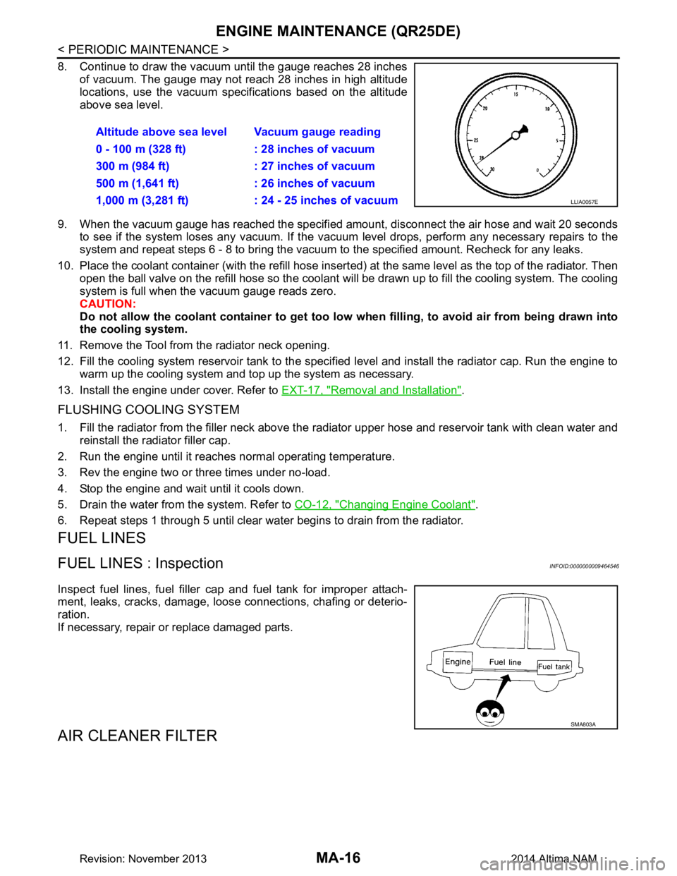
8. Continue to draw the vacuum until the gauge reaches 28 inchesof vacuum. The gauge may not reach 28 inches in high altitude
locations, use the vacuum specifications based on the altitude
above sea level.
9. When the vacuum gauge has reached the specifi ed amount, disconnect the air hose and wait 20 seconds
to see if the system loses any vacuum. If the vacuum level drops, perform any necessary repairs to the
system and repeat steps 6 - 8 to bring the vacuum to the specified amount. Recheck for any leaks.
10. Place the coolant container (with the refill hose insert ed) at the same level as the top of the radiator. Then
open the ball valve on the refill hose so the coolant will be drawn up to fill the cooling system. The cooling
system is full when the vacuum gauge reads zero.
CAUTION:
Do not allow the coolant container to get too low when filling, to avoid air from being drawn into
the cooling system.
11. Remove the Tool from the radiator neck opening.
12. Fill the cooling system reservoir tank to the specif ied level and install the radiator cap. Run the engine to
warm up the cooling system and t op up the system as necessary.
13. Install the engine under cover. Refer to EXT-17, "Removal and Installation"
.
FLUSHING COOLING SYSTEM
1. Fill the radiator from the filler neck above the radiator upper hose and reservoir tank with clean water and
reinstall the radiator filler cap.
2. Run the engine until it reaches normal operating temperature.
3. Rev the engine two or three times under no-load.
4. Stop the engine and wait until it cools down.
5. Drain the water from the system. Refer to CO-12, "Changing Engine Coolant"
.
6. Repeat steps 1 through 5 until clear water begins to drain from the radiator.
FUEL LINES
FUEL LINES : InspectionINFOID:0000000009464546
Inspect fuel lines, fuel filler cap and fuel tank for improper attach-
ment, leaks, cracks, damage, loose connections, chafing or deterio-
ration.
If necessary, repair or replace damaged parts.
AIR CLEANER FILTER
Altitude above sea level Vacuum gauge reading
0 - 100 m (328 ft) : 28 inches of vacuum
300 m (984 ft) : 27 inches of vacuum
500 m (1,641 ft) : 26 inches of vacuum
1,000 m (3,281 ft) : 24 - 25 inches of vacuum
LLIA0057E
SMA803A
Revision: November 20132014 Altima NAM
Page 3209 of 4801

ENGINE MAINTENANCE (VQ35DE)MA-25
< PERIODIC MAINTENANCE >
C
D E
F
G H
I
J
K L
M B
MA
N
O A
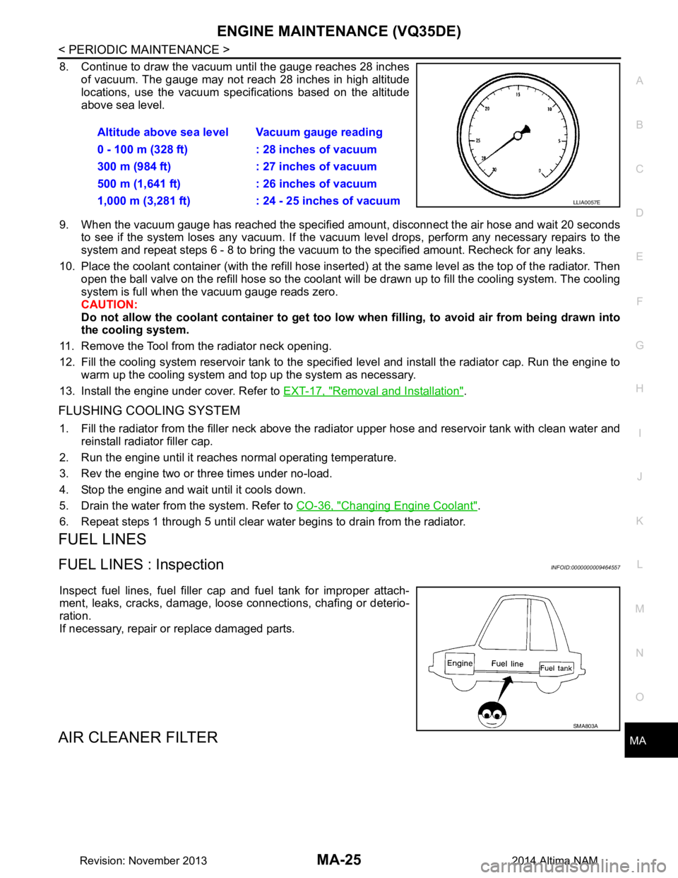
8. Continue to draw the vacuum until the gauge reaches 28 inches
of vacuum. The gauge may not reach 28 inches in high altitude
locations, use the vacuum specifications based on the altitude
above sea level.
9. When the vacuum gauge has reached the specified amount, disconnect the air hose and wait 20 seconds
to see if the system loses any vacuum. If the vacuum level drops, perform any necessary repairs to the
system and repeat steps 6 - 8 to br ing the vacuum to the specified amount. Recheck for any leaks.
10. Place the coolant container (with the refill hose inserted) at the same level as the top of the radiator. Then
open the ball valve on the refill hose so the coolant will be drawn up to fill the cooling system. The cooling
system is full when the vacuum gauge reads zero.
CAUTION:
Do not allow the coolant container to get too low when filling, to avoid air from being drawn into
the cooling system.
11. Remove the Tool from the radiator neck opening.
12. Fill the cooling system reservoir tank to the specif ied level and install the radiator cap. Run the engine to
warm up the cooling system and top up the system as necessary.
13. Install the engine under cover. Refer to EXT-17, "Removal and Installation"
.
FLUSHING COOLING SYSTEM
1. Fill the radiator from the filler neck above the r adiator upper hose and reservoir tank with clean water and
reinstall radiator filler cap.
2. Run the engine until it reaches normal operating temperature.
3. Rev the engine two or three times under no-load.
4. Stop the engine and wait until it cools down.
5. Drain the water from the system. Refer to CO-36, "Changing Engine Coolant"
.
6. Repeat steps 1 through 5 until clear water begins to drain from the radiator.
FUEL LINES
FUEL LINES : InspectionINFOID:0000000009464557
Inspect fuel lines, fuel filler cap and fuel tank for improper attach-
ment, leaks, cracks, damage, loos e connections, chafing or deterio-
ration.
If necessary, repair or replace damaged parts.
AIR CLEANER FILTER
Altitude above sea level Vacuum gauge reading
0 - 100 m (328 ft) : 28 inches of vacuum
300 m (984 ft) : 27 inches of vacuum
500 m (1,641 ft) : 26 inches of vacuum
1,000 m (3,281 ft) : 24 - 25 inches of vacuum
LLIA0057E
SMA803A
Revision: November 20132014 Altima NAM
Page 3256 of 4801

MWI
MWI-1
DRIVER INFORMATION & MULTIMEDIA
C
D E
F
G H
I
J
K L
M B
SECTION MWI
A
O P
CONTENTS
METER, WARNING LAMP & INDICATOR
PRECAUTION ................ ...............................4
PRECAUTIONS .............................................. .....4
Precaution for Supplemental Restraint System
(SRS) "AIR BAG" and "SEAT BELT PRE-TEN-
SIONER" ............................................................. ......
4
PREPARATION ............................................5
PREPARATION .............................................. .....5
Special Service Tools .......................................... ......5
Commercial Service Tools ........................................5
SYSTEM DESCRIPTION ..............................6
COMPONENT PARTS ................................... .....6
METER SYSTEM .........................................................6
METER SYSTEM : Compo nent Parts Location ........6
METER SYSTEM : Component Description ....... ......7
SYSTEM ..............................................................9
METER SYSTEM .........................................................9
METER SYSTEM : System Diagram ........................9
METER SYSTEM : System Description ....................9
METER SYSTEM : Arrangem ent of Combination
Meter ................................................................... ....
10
METER SYSTEM : Fail-Safe ..................................10
SPEEDOMETER ................ ........................................11
SPEEDOMETER : System Diagram ................... ....11
SPEEDOMETER : System Description ...................11
TACHOMETER ...................................................... ....11
TACHOMETER : System Diagram .........................12
TACHOMETER : System De scription .....................12
ENGINE COOLANT TEMPERATURE GAUGE .... ....12
ENGINE COOLANT TEMPERATURE GAUGE :
System Diagram .................................................. ....
12
ENGINE COOLANT TEMPERATURE GAUGE :
System Description ............................................. ....
12
FUEL GAUGE ........................................................ ....12
FUEL GAUGE : System Diagram ............................12
FUEL GAUGE : System Description .......................12
MASTER WARNING LAMP ................................... ....12
MASTER WARNING LAMP : System Diagram .......13
MASTER WARNING LAMP : System Description ....13
METER ILLUMINATION CONTROL ..................... ....13
METER ILLUMINATION CONTROL : System Di-
agram .................................................................. ....
13
METER ILLUMINATION CONTROL : System De-
scription ............................................................... ....
13
METER EFFECT FUNCTION ................................ ....13
METER EFFECT FUNCTION : System Diagram ....14
METER EFFECT FUNCTION : System Descrip-
tion ....................................................................... ....
14
INFORMATION DISPLAY ...................................... ....15
INFORMATION DISPLAY : System Diagram ..........15
INFORMATION DISPLAY : System Description .....15
COMPASS ............................................................. ....16
COMPASS : Description ..........................................16
DIAGNOSIS SYSTEM (METER) .......................18
Description ........................................................... ....18
CONSULT Function (METER/M&A) ........................18
ECU DIAGNOSIS INFORMATION ..............22
COMBINATION METER ...................................22
Reference Value .................................................. ....22
Fail-Safe ..................................................................27
DTC Index ...............................................................27
BCM, IPDM E/R .................................................29
List of ECU Reference .............................................29
WIRING DIAGRAM ......................................30
COMPASS .........................................................30
Revision: November 20132014 Altima NAMRevision: November 20132014 Altima NAM
Page 3263 of 4801

MWI-8
< SYSTEM DESCRIPTION >
COMPONENT PARTS
Unit Description
Combination meter Controls the following with the signals received from each unit via CAN communication and the signals
from switches and sensors:
• Speedometer
• Tachometer
• Engine coolant temperature gauge
• Fuel gauge
• Warning lamps
• Indicator lamps
• Meter illumination control
• Meter effect function
• Information display
Meter control switch Transmits the following signals to the combination meter:
• Trip reset switch signal
• Illumination control switch signal (+)
• Illumination control switch signal ( −)
ECM Transmits the following signals to the combination meter via CAN communication:
• Engine speed signal
• Engine coolant temperature signal
• Engine oil pressure warning signal
• Fuel consumption monitor signal
ABS actuator and electric unit
(control unit) Transmits the vehicle speed signal to the combination meter via CAN communication.
Power steering control module Transmits the EPS signal to the combination meter via CAN communication.
BCM Transmits the following signals to the combination meter via CAN communication:
• Tire pressure information
• Position light request signal
• Low tire pressure warning lamp signal
• Door switch signal
• Trunk lamp switch signal
TCM Receives the O/D OFF switch signal from the combination meter via CAN communication.
Transmits the O/D OFF indicator request signal to the combination meter via CAN communication.
CVT shift selector switch
(overdrive co ntrol switch)
(with QR25DE) Transmits the O/D OFF switch signal to the combination meter
Fuel level sensor unit Transmits the fuel level sensor signal to the combination meter.
Seat belt buckle switch LH
(RH similar) Transmits the seat belt buckle switch LH signal to the combination meter.
Air bag diagnosis sensor unit Transmits the following signals to the combination meter:
• Seat belt buckle switch RH signal
• Air bag warning indicator
Engine oil pressure sensor Transmits the engine oil pressure sensor signal to the ECM.
Ambient sensor Transmits the ambient sensor signal to the IPDM E/R.
A/C auto amp. • Receives the ambient sensor signal from the IPDM E/R (with auto A/C).
• Transmits the ambient sensor signal to the combination meter via CAN communication.
Parking brake switch Transmits the parking brake switch signal to the combination meter.
Washer fluid level switch Transmits the washer fluid level switch signal to the combination meter.
Steering switch Transmits the following signals to the information display:
• Display signal
• Menu up signal
• Menu down signal
• Enter signal
• Back signal
IPDM E/R • Receives the ambient sensor signal from the ambient sensor.
• Transmits the ambient sensor signal to the combination meter (without auto A/C).
• Transmits the ambient sensor signal to the A/C auto amp (with auto A/C).
Brake fluid level switch Transmits the brake fluid level switch signal to the combination meter.
Revision: November 20132014 Altima NAMRevision: November 20132014 Altima NAM
Page 3266 of 4801

MWI
SYSTEMMWI-11
< SYSTEM DESCRIPTION >
C
D E
F
G H
I
J
K L
M B
A
O P
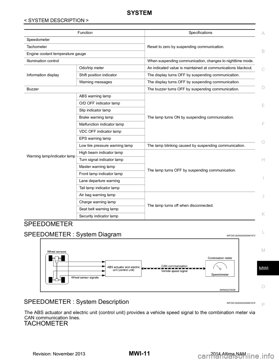
SPEEDOMETER
SPEEDOMETER : System DiagramINFOID:0000000009461675
SPEEDOMETER : System DescriptionINFOID:0000000009461676
The ABS actuator and electric unit (control unit) provi des a vehicle speed signal to the combination meter via
CAN communication lines.
TACHOMETER
Function Specifications
Speedometer Reset to zero by suspending communication.
Tachometer
Engine coolant temperature gauge
Illumination control When suspending communication, changes to nighttime mode.
Information display Odo/trip meter An indicated value is maintained at communications blackout.
Shift position indicator The display turns OFF by suspending communication.
Warning messages The display turns OFF by suspending communication.
Buzzer The buzzer turns OFF by suspending communication.
Warning lamp/indicator lamp ABS warning lamp
The lamp turns ON by suspending communication.
O/D OFF indicator lamp
Slip indicator lamp
Brake warning lamp
Malfunction indicator lamp
VDC OFF indicator lamp
EPS warning lamp
Low tire pressure warning lamp The lamp blinking caused by suspending communication.
High beam indicator lamp
The lamp turns OFF by suspending communication.
Turn signal indicator lamp
Master warning lamp
Front lamp indicator lamp
Lane departure warning
Tail lamp indicator lamp
Air bag warning lamp
The lamp turns off when disconnected.
Charge warning lamp
Seat belt warning lamp
Security indicator lamp
AWNIA2379GB
Revision: November 20132014 Altima NAMRevision: November 20132014 Altima NAM