2014 NISSAN TEANA ignition
[x] Cancel search: ignitionPage 3691 of 4801
RF-26
< DTC/CIRCUIT DIAGNOSIS >
MOONROOF SWITCH
MOONROOF SWITCH
DescriptionINFOID:0000000009461309
Transmits switch operation signal to moonroof motor assembly.
Diagnosis ProcedureINFOID:0000000009461310
Regarding Wiring Diagram information, refer to RF-12, "Wiring Diagram".
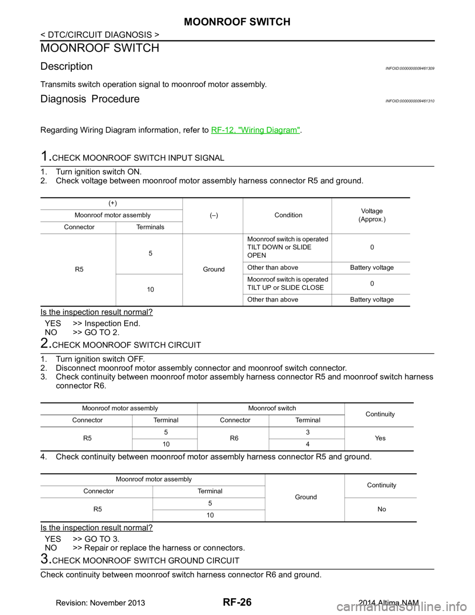
1.CHECK MOONROOF SWITCH INPUT SIGNAL
1. Turn ignition switch ON.
2. Check voltage between moonroof motor assembly harness connector R5 and ground.
Is the inspection result normal?
YES >> Inspection End.
NO >> GO TO 2.
2.CHECK MOONROOF SWITCH CIRCUIT
1. Turn ignition switch OFF.
2. Disconnect moonroof motor assembly connector and moonroof switch connector.
3. Check continuity between moonroof motor assemb ly harness connector R5 and moonroof switch harness
connector R6.
4. Check continuity between moonroof moto r assembly harness connector R5 and ground.
Is the inspection result normal?
YES >> GO TO 3.
NO >> Repair or replace the harness or connectors.
3.CHECK MOONROOF SWITCH GROUND CIRCUIT
Check continuity between moonroof switch harness connector R6 and ground.
(+)
(–) Condition Voltag e
(Approx.)
Moonroof motor assembly
Connector Terminals
R5 5
GroundMoonroof switch is operated
TILT DOWN or SLIDE
OPEN 0
Other than above Battery voltage
10 Moonroof switch is operated
TILT UP or SLIDE CLOSE 0
Other than above Battery voltage
Moonroof motor assembly Moonroof switch Continuity
Connector Terminal Connector Terminal
R5 5
R6 3
Ye s
10 4
Moonroof motor assembly GroundContinuity
Connector Terminal
R5 5
No
10
Revision: November 20132014 Altima NAMRevision: November 20132014 Altima NAM
Page 3692 of 4801
MOONROOF SWITCHRF-27
< DTC/CIRCUIT DIAGNOSIS >
C
D E
F
G H
I
J
L
M A
B
RF
N
O P
Is the inspection result normal?
YES >> GO TO 4.
NO >> Repair or replace the harness or connectors.
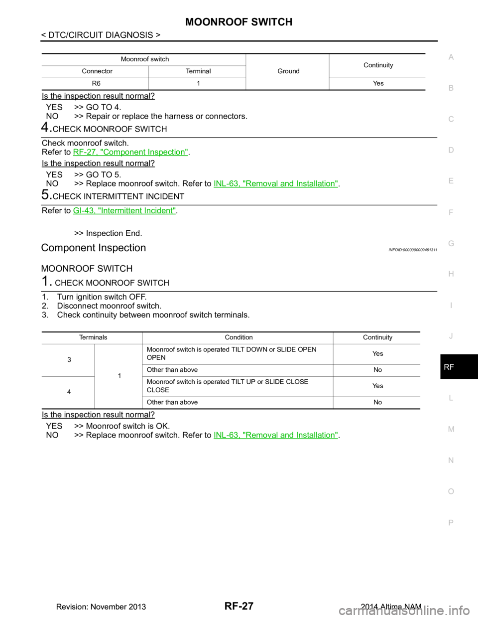
4.CHECK MOONROOF SWITCH
Check moonroof switch.
Refer to RF-27, "Component Inspection"
.
Is the inspection result normal?
YES >> GO TO 5.
NO >> Replace moonroof switch. Refer to INL-63, "Removal and Installation"
.
5.CHECK INTERMITTENT INCIDENT
Refer to GI-43, "Intermittent Incident"
.
>> Inspection End.
Component InspectionINFOID:0000000009461311
MOONROOF SWITCH
1. CHECK MOONROOF SWITCH
1. Turn ignition switch OFF.
2. Disconnect moonroof switch.
3. Check continuity between moonroof switch terminals.
Is the inspection result normal?
YES >> Moonroof switch is OK.
NO >> Replace moonroof switch. Refer to INL-63, "Removal and Installation"
.
Moonroof switch
GroundContinuity
Connector Terminal
R6 1 Yes
Terminals Condition Continuity
3 1Moonroof switch is operated TILT DOWN or SLIDE OPEN
OPEN Ye s
Other than above No
4 Moonroof switch is operated TILT UP or SLIDE CLOSE
CLOSE Ye s
Other than above No
Revision: November 20132014 Altima NAMRevision: November 20132014 Altima NAM
Page 3693 of 4801
RF-28
< DTC/CIRCUIT DIAGNOSIS >
DOOR SWITCH
DOOR SWITCH
DescriptionINFOID:0000000009461312
Detects door open/close condition.
Component Function CheckINFOID:0000000009461313
1.CHECK FUNCTION
With CONSULT
Check door switches DOOR SW-DR, DOOR SW-AS in Data Monitor mode with CONSULT.
Is the inspection result normal?
YES >> Door switch is OK.
NO >> Refer to RF-28, "Diagnosis Procedure"
.
Diagnosis ProcedureINFOID:0000000009461314
Regarding Wiring Diagram information, refer to DLK-51, "Wiring Diagram".
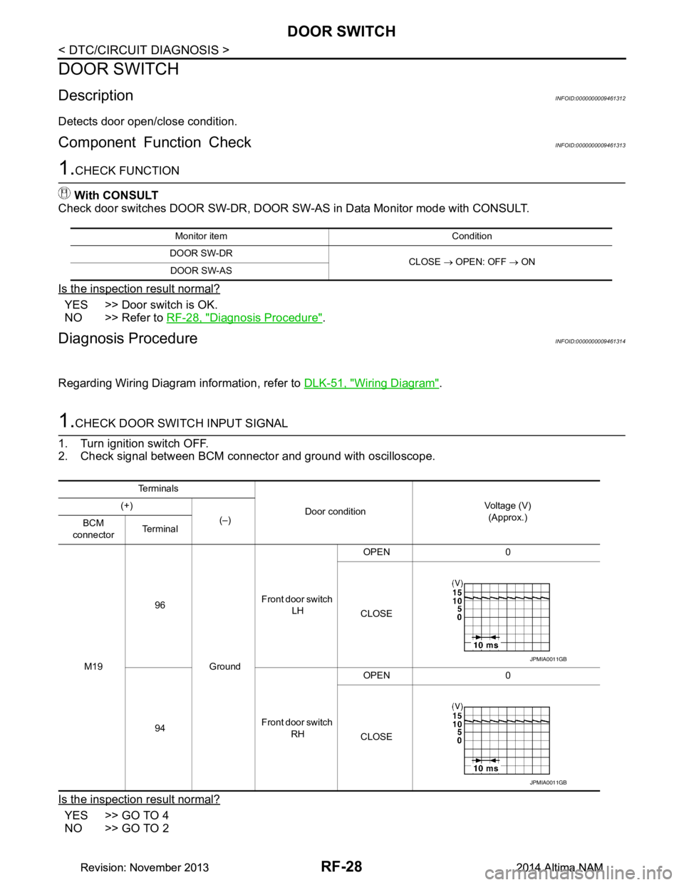
1.CHECK DOOR SWITCH INPUT SIGNAL
1. Turn ignition switch OFF.
2. Check signal between BCM connector and ground with oscilloscope.
Is the inspection result normal?
YES >> GO TO 4
NO >> GO TO 2
Monitor item Condition
DOOR SW-DR CLOSE → OPEN: OFF → ON
DOOR SW-AS
Te r m i n a l s
Door condition Voltage (V)
(Approx.)
(+)
(–)
BCM
connector Te r m i n a l
M19 96
GroundFront door switch
LH OPEN 0
CLOSE
94 Front door switch
RH OPEN 0
CLOSE
JPMIA0011GB
JPMIA0011GB
Revision: November 20132014 Altima NAMRevision: November 20132014 Altima NAM
Page 3694 of 4801
DOOR SWITCHRF-29
< DTC/CIRCUIT DIAGNOSIS >
C
D E
F
G H
I
J
L
M A
B
RF
N
O P
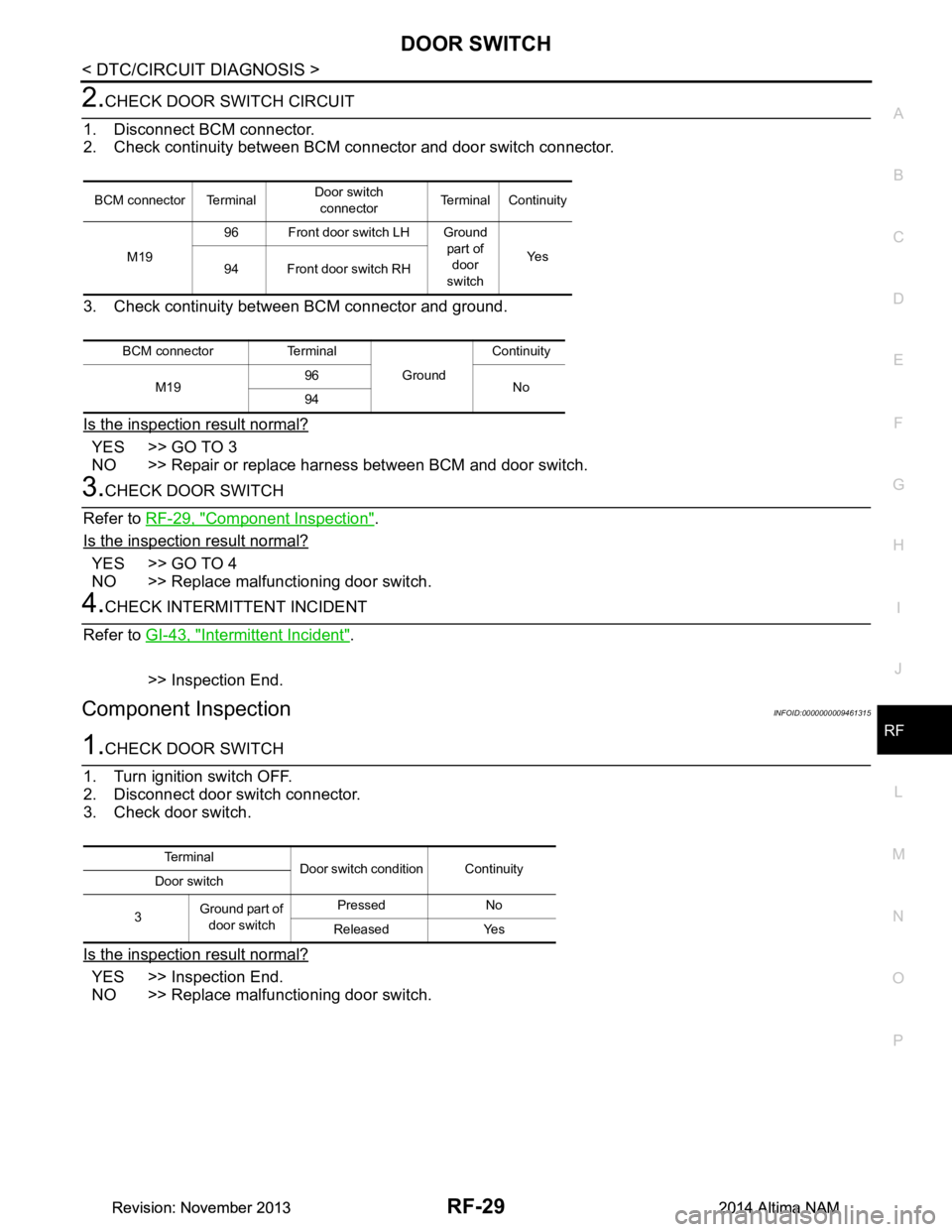
2.CHECK DOOR SWITCH CIRCUIT
1. Disconnect BCM connector.
2. Check continuity between BCM connector and door switch connector.
3. Check continuity between BCM connector and ground.
Is the inspection result normal?
YES >> GO TO 3
NO >> Repair or replace harness between BCM and door switch.
3.CHECK DOOR SWITCH
Refer to RF-29, "Component Inspection"
.
Is the inspection result normal?
YES >> GO TO 4
NO >> Replace malfunctioning door switch.
4.CHECK INTERMITTENT INCIDENT
Refer to GI-43, "Intermittent Incident"
.
>> Inspection End.
Component InspectionINFOID:0000000009461315
1.CHECK DOOR SWITCH
1. Turn ignition switch OFF.
2. Disconnect door switch connector.
3. Check door switch.
Is the inspection result normal?
YES >> Inspection End.
NO >> Replace malfunctioning door switch.
BCM connector Terminal Door switch
connector Terminal Continuity
M19 96 Front door switch LH Ground
part of
door
switch Ye s
94 Front door switch RH
BCM connector Terminal GroundContinuity
M19 96
No
94
Te r m i n a l Door switch condition Continuity
Door switch
3 Ground part of
door switch Pressed No
Released Yes
Revision: November 20132014 Altima NAMRevision: November 20132014 Altima NAM
Page 3719 of 4801
RSU-2
< PRECAUTION >
PRECAUTIONS
PRECAUTION
PRECAUTIONS
Precaution for Supplemental Restraint System (SRS) "AIR BAG" and "SEAT BELT
PRE-TENSIONER"
INFOID:0000000009951707
The Supplemental Restraint System such as “A IR BAG” and “SEAT BELT PRE-TENSIONER”, used along
with a front seat belt, helps to reduce the risk or severi ty of injury to the driver and front passenger for certain
types of collision. Information necessary to service the system safely is included in the SR and SB section of
this Service Manual.
WARNING:
• To avoid rendering the SRS inopera tive, which could increase the risk of personal injury or death in
the event of a collision which would result in air bag inflation, all maintenance must be performed by
an authorized NISS AN/INFINITI dealer.
• Improper maintenance, including in correct removal and installation of the SRS, can lead to personal
injury caused by unintent ional activation of the system. For re moval of Spiral Cable and Air Bag
Module, see the SR section.
• Do not use electrical test equipmen t on any circuit related to the SRS unless instructed to in this
Service Manual. SRS wiring harn esses can be identified by yellow and/or orange harnesses or har-
ness connectors.
PRECAUTIONS WHEN USING POWER TOOLS (AIR OR ELECTRIC) AND HAMMERS
WARNING:
• When working near the Airbag Diagnosis Sensor Unit or other Airbag System sensors with the Igni-
tion ON or engine running, DO NOT use air or electri c power tools or strike near the sensor(s) with a
hammer. Heavy vibration could activate the sensor( s) and deploy the air bag(s), possibly causing
serious injury.
• When using air or electric power tools or hammers , always switch the Ignition OFF, disconnect the
battery and wait at least three minutes before performing any service.
General PrecautionsINFOID:0000000009464451
• When installing rubber bushings, the final tightening mu st be carried out under unladen conditions with tires
on ground. Oil might shorten the life of rubber bushings. Be sure to wipe off any spilled oil.
- Unladen conditions mean that fuel, engine coolant and lubricant are full. Spare tire, jack, hand tools and mats are in designated positions.
• After servicing suspension parts, be sure to check wheel alignment.
• Self-lock nuts are not reusable. Always use new ones when installing. Since new self-lock nuts are pre-oiled,
tighten as they are.
Revision: November 20132014 Altima NAM
Page 3737 of 4801
SB-2
< PRECAUTION >
PRECAUTIONS
PRECAUTION
PRECAUTIONS
Precaution for Supplemental Restraint System (SRS) "AIR BAG" and "SEAT BELT
PRE-TENSIONER"
INFOID:0000000009951757
The Supplemental Restraint System such as “A IR BAG” and “SEAT BELT PRE-TENSIONER”, used along
with a front seat belt, helps to reduce the risk or severi ty of injury to the driver and front passenger for certain
types of collision. Information necessary to service the system safely is included in the SR and SB section of
this Service Manual.
WARNING:
• To avoid rendering the SRS inopera tive, which could increase the risk of personal injury or death in
the event of a collision which would result in air bag inflation, all maintenance must be performed by
an authorized NISS AN/INFINITI dealer.
• Improper maintenance, including in correct removal and installation of the SRS, can lead to personal
injury caused by unintent ional activation of the system. For re moval of Spiral Cable and Air Bag
Module, see the SR section.
• Do not use electrical test equipmen t on any circuit related to the SRS unless instructed to in this
Service Manual. SRS wiring harn esses can be identified by yellow and/or orange harnesses or har-
ness connectors.
PRECAUTIONS WHEN USING POWER TOOLS (AIR OR ELECTRIC) AND HAMMERS
WARNING:
• When working near the Airbag Diagnosis Sensor Unit or other Airbag System sensors with the Igni-
tion ON or engine running, DO NOT use air or electri c power tools or strike near the sensor(s) with a
hammer. Heavy vibration could activate the sensor( s) and deploy the air bag(s), possibly causing
serious injury.
• When using air or electric power tools or hammers , always switch the Ignition OFF, disconnect the
battery and wait at least three minutes before performing any service.
Precaution for Seat Belt ServiceINFOID:0000000009462957
CAUTION:
• Before removing the seat belt pre-tensioner assembl y, turn the ignition switch OFF, disconnect both
battery terminals and wait at least three minutes. For approximately three minutes after the battery
terminals have been removed, it is still possible for the air bag and seat belt pre-tensioner to deploy.
Therefore, do not attempt work on any SRS conn ectors or wires until at least three minutes have
passed.
• After replacing or reinstalling seat belt pre -tensioner assembly or reconnecting seat belt pre-ten-
sioner assembly connector, make sure entire SRS operates properly. Refer to SRC-15, "SRS Opera-
tion Check".
• Do not disassemble buckle or seat belt assembly.
• Replace anchor bolts if th ey are deformed or worn out.
• Do not oil tongue or buckle.
• If any component of seat belt assembly is questionable, do not re pair. Replace the whole seat belt
assembly.
• If webbing is cut, frayed or damaged, replace seat belt assembly.
• When replacing seat belt assembly, use a genuine NISSAN seat belt assembly.
Precaution for WorkINFOID:0000000009462958
• When removing or disassembling each component, be careful not to damage or deform it. If a component may be subject to interference, be sure to protect it with a shop cloth.
• When removing (disengaging) components with a screwdriver or similar tool, be sure to wrap the component with a shop cloth or vinyl tape to protect it.
• Protect the removed parts with a s hop cloth and prevent them from being dropped.
• Replace a deformed or damaged clip.
• If a part is specified as a non-reusable part, always replace it with a new one.
• Be sure to tighten bolts and nuts securely to the specified torque.
• After installation is complete, be sure to check that each part works properly.
Revision: November 20132014 Altima NAM
Page 3740 of 4801
COMPONENT INSPECTIONSB-5
< BASIC INSPECTION >
C
D E
F
G
I
J
K L
M A
B
SB
N
O P
BASIC INSPECTION
COMPONENT INSPECTION
InspectionINFOID:0000000009462960
AFTER A COLLISION
WARNING:
Inspect all seat belt assemblies in cluding retractors and attaching hardware after any collision.
NISSAN/INFINITI recommends that all seat belt assemblies in use during a collision be replaced
unless the collision was minor and th e belts show no damage and continue to operate properly. Fail-
ure to do so could result in serious personal inju ry in an accident. Seat belt assemblies not in use dur-
ing a collision should also be replaced if either da mage or improper operation is noted. Seat belt pre-
tensioners should be replaced even if the seat belts are not in use during a frontal collision in which
the air bags are deployed.
Replace any seat belt assembly (including anchor bolts) if:
• The seat belt was in use at the time of a collision (except for minor collisions and the belts, retractors and
buckles show no damage and continue to operate properly).
• The seat belt was damaged in an accident (i.e. torn webbing, bent retractor or guide, etc.).
• The seat belt attaching point is damaged in an accident . Inspect the seat belt attaching area for damage or
distortion and repair if necessary before installing a new seat belt assembly.
• Anchor bolts are deformed or worn out.
• The seat belt pre-tensioner should be replaced even if t he seat belts are not in use during the collision in
which the air bags are deployed.
PRELIMINARY CHECKS
1. Check the seat belt warning lamp for proper operation per the following:
a. Turn ignition switch ON. The seat belt warning lamp should illuminate.
b. Fasten driver seat belt. The seat belt warning lamp should turn OFF.
2. If the air bag warning lamp is blinking, perform self-diagnosis with CONSULT and air bag warning lamp. Refer to SRC-17, "Trouble Diagnosis without CONSULT"
.
3. Check that the seat belt retractor, seat belt anchor and buckle bolts are tightened firmly.
4. Check the shoulder seat belt guide and shoulder belt height adjuster for front seats. Check that guide
swivels freely and that webbing lays flat and does not bind in guide. Check that height adjuster operates
properly and holds securely.
5. Check retractor operation:
a. Fully extend the seat belt webbing and check for twists, tears or other damage.
b. Allow the seat belt to retract. Check that webbing retu rns smoothly and completely into the retractor. If the
seat belt does not return smoothly, wipe the inside of t he loops with a clean paper cloth. Dirt build-up in the
loops of the upper anchors can cause t he seat belts to retract slowly.
c. Fasten the seat belt. Check that seat belt returns sm oothly and completely to the retractor. If the webbing
does not return smoothly, the cause may be an accu mulation of dust or dirt. Use the “SEAT BELT TAPE
SET” and perform the following steps.
d. Inspect the front seat belt D-ring anchor 1. Pull the seat belt out to a length of 500 mm (19.69 in) or more.
2. Hold the seat belt at the center pillar webbing opening with a clip or other device.
3. Pass a thin wire through the D-ring anchor webbing opening. Hold both ends of the wire and pull it tightly while moving it up and down several times along the webbing opening surface to remove dirt
stuck there.
4. Any dirt that cannot be removed with the wire can be removed by cleaning the opening with a clean
cloth.
5. Apply tape at the point where the webbing contacts the D-ring anchor webbing opening. NOTE:
Apply the tape so that there is no slack or wrinkling.
6. Remove the clip holding the seat belt and check that the webbing returns smoothly.
6. Repeat steps above if necessary to check the other seat belts.
Revision: November 20132014 Altima NAM
Page 3751 of 4801
SE-2
< PRECAUTION >
PRECAUTIONS
PRECAUTION
PRECAUTIONS
Precaution for Supplemental Restraint System (SRS) "AIR BAG" and "SEAT BELT
PRE-TENSIONER"
INFOID:0000000009951559
The Supplemental Restraint System such as “A IR BAG” and “SEAT BELT PRE-TENSIONER”, used along
with a front seat belt, helps to reduce the risk or severi ty of injury to the driver and front passenger for certain
types of collision. Information necessary to service the system safely is included in the SR and SB section of
this Service Manual.
WARNING:
• To avoid rendering the SRS inopera tive, which could increase the risk of personal injury or death in
the event of a collision which would result in air bag inflation, all maintenance must be performed by
an authorized NISS AN/INFINITI dealer.
• Improper maintenance, including in correct removal and installation of the SRS, can lead to personal
injury caused by unintent ional activation of the system. For re moval of Spiral Cable and Air Bag
Module, see the SR section.
• Do not use electrical test equipmen t on any circuit related to the SRS unless instructed to in this
Service Manual. SRS wiring harn esses can be identified by yellow and/or orange harnesses or har-
ness connectors.
PRECAUTIONS WHEN USING POWER TOOLS (AIR OR ELECTRIC) AND HAMMERS
WARNING:
• When working near the Airbag Diagnosis Sensor Unit or other Airbag System sensors with the Igni-
tion ON or engine running, DO NOT use air or electri c power tools or strike near the sensor(s) with a
hammer. Heavy vibration could activate the sensor( s) and deploy the air bag(s), possibly causing
serious injury.
• When using air or electric power tools or hammers , always switch the Ignition OFF, disconnect the
battery and wait at least three minutes before performing any service.
Precaution for WorkINFOID:0000000009462924
• When removing or disassembling each component, be careful not to damage or deform it. If a component may be subject to interference, be sure to protect it with a shop cloth.
• When removing (disengaging) components with a screwdriver or similar tool, be sure to wrap the component with a shop cloth or vinyl tape to protect it.
• Protect the removed parts with a s hop cloth and prevent them from being dropped.
• Replace a deformed or damaged clip.
• If a part is specified as a non-reusable part, always replace it with a new one.
• Be sure to tighten bolts and nuts securely to the specified torque.
• After installation is complete, be sure to check that each part works properly.
• Follow the steps below to clean components:
- Water soluble dirt:
• Dip a soft cloth into lukewarm water, wring the water out of the cloth and wipe the dirty area.
• Then rub with a soft, dry cloth.
- Oily dirt:
• Dip a soft cloth into lukewarm water with mild detergent (concentration: within 2 to 3%) and wipe the dirty area.
• Then dip a cloth into fresh water, wring the water out of the cloth and wipe the detergent off.
• Then rub with a soft, dry cloth.
- Do not use organic solvent such as thinner, benzene, alcohol or gasoline.
- For genuine leather seats, use a genuine leather seat cleaner.
Revision: November 20132014 Altima NAMRevision: November 20132014 Altima NAM