2014 NISSAN TEANA ignition
[x] Cancel search: ignitionPage 3668 of 4801

PRECAUTIONSRF-3
< PRECAUTION >
C
D E
F
G H
I
J
L
M A
B
RF
N
O P
PRECAUTION
PRECAUTIONS
Precaution for Supplemental Restraint System (SRS) "AIR BAG" and "SEAT BELT
PRE-TENSIONER"
INFOID:0000000009951570
The Supplemental Restraint System such as “A IR BAG” and “SEAT BELT PRE-TENSIONER”, used along
with a front seat belt, helps to reduce the risk or severi ty of injury to the driver and front passenger for certain
types of collision. Information necessary to service t he system safely is included in the SR and SB section of
this Service Manual.
WARNING:
• To avoid rendering the SRS inoper ative, which could increase the risk of personal injury or death in
the event of a collision which would result in air bag inflation, all maintenance must be performed by
an authorized NISSAN/INFINITI dealer.
• Improper maintenance, including in correct removal and installation of the SRS, can lead to personal
injury caused by unintentional act ivation of the system. For removal of Spiral Cable and Air Bag
Module, see the SR section.
• Do not use electrical test equipm ent on any circuit related to the SRS unless instructed to in this
Service Manual. SRS wiring harnesses can be identi fied by yellow and/or orange harnesses or har-
ness connectors.
PRECAUTIONS WHEN USING POWER TOOLS (AIR OR ELECTRIC) AND HAMMERS
WARNING:
• When working near the Airbag Diagnosis Sensor Un it or other Airbag System sensors with the Igni-
tion ON or engine running, DO NOT use air or el ectric power tools or strike near the sensor(s) with a
hammer. Heavy vibration could activate the sensor( s) and deploy the air bag(s), possibly causing
serious injury.
• When using air or electric power tools or hammers , always switch the Ignition OFF, disconnect the
battery and wait at least three mi nutes before performing any service.
Precaution for WorkINFOID:0000000009461288
• When removing or disassembling each component, be ca reful not to damage or deform it. If a component
may be subject to interference, be sure to protect it with a shop cloth.
• When removing (disengaging) components with a screwdriver or similar tool, be sure to wrap the component with a shop cloth or vinyl tape to protect it.
• Protect the removed parts with a shop cloth and prevent them from being dropped.
• Replace a deformed or damaged clip.
• If a part is specified as a non-reusabl e part, always replace it with a new one.
• Be sure to tighten bolts and nuts securely to the specified torque.
• After installation is complete, be sure to check that each part works properly.
• Follow the steps below to clean components:
- Water soluble dirt:
• Dip a soft cloth into lukewarm water, wring the water out of the cloth and wipe the dirty area.
• Then rub with a soft, dry cloth.
-Oily dirt:
• Dip a soft cloth into lukewarm water with mild detergent (concentration: within 2 to 3%) and wipe the dirty area.
• Then dip a cloth into fresh water, wring the water out of the cloth and wipe the detergent off.
• Then rub with a soft, dry cloth.
- Do not use organic solvent such as thinner, benzene, alcohol or gasoline.
- For genuine leather seats, use a genuine leather seat cleaner.
Revision: November 20132014 Altima NAMRevision: November 20132014 Altima NAM
Page 3671 of 4801

RF-6
< SYSTEM DESCRIPTION >
SYSTEM
SYSTEM
MOONROOF
MOONROOF : System DiagramINFOID:0000000009461293
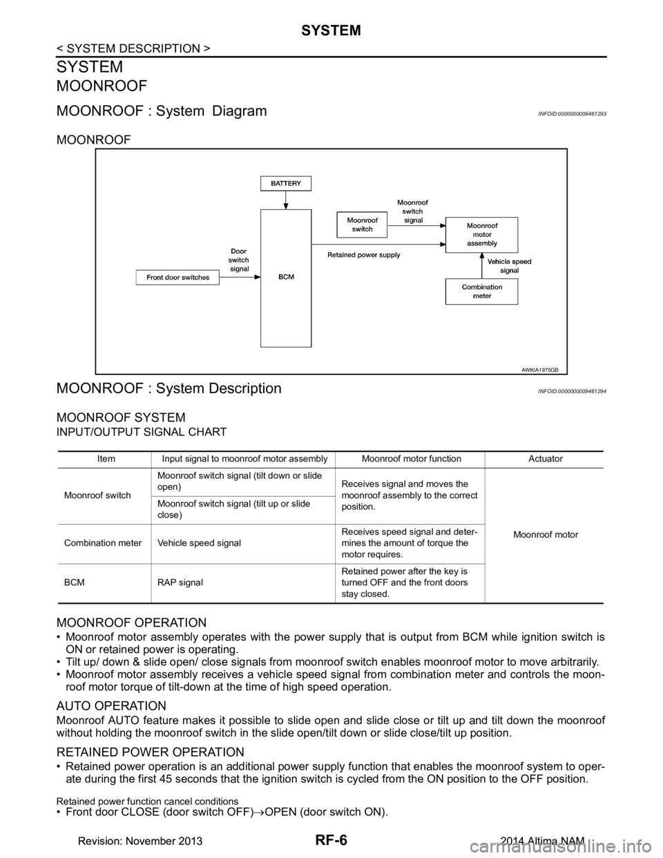
MOONROOF
MOONROOF : System DescriptionINFOID:0000000009461294
MOONROOF SYSTEM
INPUT/OUTPUT SIGNAL CHART
MOONROOF OPERATION
• Moonroof motor assembly operates with the power supply that is output from BCM while ignition switch isON or retained power is operating.
• Tilt up/ down & slide open/ close signals from moonroof switch enables moonroof motor to move arbitrarily.
• Moonroof motor assembly receives a vehicle speed signal from combination meter and controls the moon- roof motor torque of tilt-down at the time of high speed operation.
AUTO OPERATION
Moonroof AUTO feature makes it possible to slide open and slide close or tilt up and tilt down the moonroof
without holding the moonroof switch in the slide open/tilt down or slide close/tilt up position.
RETAINED POWER OPERATION
• Retained power operation is an additional power supply function that enables the moonroof system to oper-
ate during the first 45 seconds that the ignition switch is cycled from the ON position to the OFF position.
Retained power function cancel conditions• Front door CLOSE (door switch OFF)→OPEN (door switch ON).
AWKIA1975GB
Item Input signal to moonroof motor assembly Moonroof motor function Actuator
Moonroof switch Moonroof switch signal (tilt down or slide
open) Receives signal and moves the
moonroof assembly to the correct
position.
Moonroof motor
Moonroof switch signal (tilt up or slide
close)
Combination meter Vehicle speed signal Receives speed signal and deter-
mines the amount of torque the
motor requires.
BCM RAP signal Retained power after the key is
turned OFF and the front doors
stay closed.
Revision: November 20132014 Altima NAMRevision: November 20132014 Altima NAM
Page 3672 of 4801

SYSTEMRF-7
< SYSTEM DESCRIPTION >
C
D E
F
G H
I
J
L
M A
B
RF
N
O P
• When ignition switch is ON again.
• When timer time passes. (45 seconds)
ANTI-PINCH FUNCTION
The CPU of moonroof motor assembly monitors t he moonroof motor operation and the moonroof position
(fully-closed or other) by the signals from moonroof motor.
When moonroof motor detects an interruption during t he following slide close and tilt down operation, moon-
roof switch controls the motor for open and the moonroof will operate until full up position (when tilt down oper-
ates) or 100 mm (3.94 in) or more in an open direction (when slide close operates):
• Close operation and tilt down when ignition switch is in the “ON” position
Revision: November 20132014 Altima NAMRevision: November 20132014 Altima NAM
Page 3676 of 4801

MOONROOF MOTOR ASSEMBLYRF-11
< ECU DIAGNOSIS INFORMATION >
C
D E
F
G H
I
J
L
M A
B
RF
N
O P
MOONROOF MOTOR ASSEMBLY
Reference ValueINFOID:0000000009461298
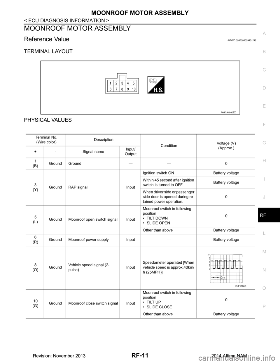
TERMINAL LAYOUT
PHYSICAL VALUES
AWKIA1980ZZ
Te r m i n a l N o . (Wire color) Description
ConditionVoltage (V)
(Approx.)
+ - Signal name Input/
Output
1
(B) Ground Ground — — 0
3
(Y) Ground RAP signal Input Ignition switch ON Battery voltage
Within 45 second after ignition
switch is turned to OFF. Battery voltage
When driver side or passenger
side door is opened during re-
tained power operation. 0
5
(L) Ground Moonroof open switch signal Input Moonroof switch in following
position
•TILT DOWN
• SLIDE OPEN 0
Other than above Battery voltage
6
(R) Ground Moonroof power supply Input — Battery voltage
8
(O) Ground
Vehicle speed signal (2-
pulse) InputSpeedometer operated [When
vehicle speed is approx.40km/
h (25MPH)]
10
(G) Ground Moonroof close switch signal Input Moonroof switch in following
position
•TILT UP
•SLIDE CLOSE 0
Other than above Battery voltage
ELF1080D
Revision: November 20132014 Altima NAMRevision: November 20132014 Altima NAM
Page 3685 of 4801

RF-20
< BASIC INSPECTION >
INSPECTION AND ADJUSTMENT
INSPECTION AND ADJUSTMENT
ADDITIONAL SERVICE WHEN REPLACING CONTROL UNIT
ADDITIONAL SERVICE WHEN REPL ACING CONTROL UNIT : Description
INFOID:0000000009461301
MEMORY RESET PROCEDURE
1. Please observe the following instructi ons at confirming the moonroof operation.
NOTE:
Do not disconnect the electronic power while the moonroof is operating or within 5 seconds after the
moonroof stops. (to wipe-out the memory of lid position and operating friction.)
2. Initialization of system should be conducted after the following conditions. • When the moonroof motor is changed.
• When the moonroof does not operate normally. (Incomplete initialization conditions)
ADDITIONAL SERVICE WHEN REPLACING CONTROL UNIT : Special Repair Re-
quirement
INFOID:0000000009461302
INITIALIZATION PROCEDURE
If the moonroof does not open or clos e automatically, use the following procedure to return moonroof opera-
tion to normal.
NOTE:
If the moonroof switch is released at any time duri ng step 4, the procedure must be started over again. Leave
the ignition switch ON for at least 2 seconds after this procedure.
1. Push the ignition switch to the ON position.
2. Hold the moonroof switch in the tilt up position. Release the switch when the moonroof has reached the
full tilt up position.
3. Hold the moonroof switch in the tilt up position agai n. After a delay, the moonroof will backup. Release the
switch.
4. Within 4 seconds of releasing the switch in step 3, hold the moonroof switch in the tilt up position again.
The moonroof will move from the full tilt-up → slide-close → slide-open → slide-close → tilt-up → slide-
close. Release the switch, initialization is complete if the moonroof operates normally.
ANTI-PINCH FUNCTION
1. Fully open the moonroof to the full open position.
2. Place a piece of wood at the fully closed position.
3. Close the moonroof completely with auto-slide close function.
4. Moonroof should make contact and then tilt up in reverse for 100mm (3.94 in.) (approx.).
CAUTION:
• Do not test the anti-pinch functi on with your hands or other part of body parts because they may be
pinched.
• Depending on environment and drivin g conditions, if a similar impact or load is applied to the moon-
roof it may lower.
• Test the auto-slide operation before inspectio n when the system initialization is performed.
• Perform the initialization proced ure when the auto-slide operation or anti-pinch function does not
operate normally.
Revision: November 20132014 Altima NAMRevision: November 20132014 Altima NAM
Page 3687 of 4801

RF-22
< DTC/CIRCUIT DIAGNOSIS >
POWER SUPPLY AND GROUND CIRCUIT
MOONROOF MOTOR ASSEMBLY : Component Function Check
INFOID:0000000009461305
1. CHECK MOONROOF MOTOR FUNCTION
Do tilt up/down & slide open/close functi ons operate normally with moonroof switch?
Is the inspection result normal?
YES >> Moonroof motor assembly is OK.
NO >> Refer to RF-22, "MOONROOF MOTOR ASSEMBLY : Diagnosis Procedure"
.
MOONROOF MOTOR ASSEMB LY : Diagnosis ProcedureINFOID:0000000009461306
Regarding Wiring Diagram information, refer to RF-12, "Wiring Diagram".
MOONROOF MOTOR ASSEMBLY
1. CHECK POWER SUPPLY CIRCUIT
1. Turn ignition switch OFF.
2. Disconnect moonroof motor assembly connector.
3. Turn ignition switch ON.
4. Check voltage between moonroof motor assembly connector R5 and ground.
Is the inspection result normal?
YES >> GO TO 2.
NO >> GO TO 3.
2. CHECK GROUND CIRCUIT
1. Turn ignition switch OFF.
2. Check continuity between moonroof motor assembly connector R5 and ground.
Is the inspection result normal?
YES >> GO TO 5.
NO >> Repair or replace the harness or connectors.
3. CHECK MOONROOF MOTOR CIRCUIT
1. Turn ignition switch OFF.
2. Disconnect BCM.
3. Check continuity between BCM connector M 21 and moonroof motor assembly connector R5.
4. Check continuity between BCM connector M21 and ground.
Is the inspection result normal?
Moonroof motor assembly connector Terminal Ground Vol tag e
(Approx.)
R5 3
Battery voltage
6
Moonroof motor assembly connector Terminal GroundContinuity
R5 1 Yes
BCM connector Terminal Moonroof motor assembly connector Terminal Continuity
M21 140
R5 3
Ye s
141 6
BCM connector Terminal GroundContinuity
M21 140
No
141
Revision: November 20132014 Altima NAMRevision: November 20132014 Altima NAM
Page 3688 of 4801

POWER SUPPLY AND GROUND CIRCUITRF-23
< DTC/CIRCUIT DIAGNOSIS >
C
D E
F
G H
I
J
L
M A
B
RF
N
O P
YES >> GO TO 4.
NO >> Repair or replace the harness or connectors.
4. CHECK BCM POWER SUPPLY
1. Connect BCM.
2. Check voltage between BCM connector M21 and ground.
Is the inspection result normal?
YES >> Check condition of harness and connectors.
NO >> Replace BCM. Refer to BCS-80, "Removal and Installation"
.
5. CHECK MOONROOF SWITCH INPUT SIGNAL
1. Connect moonroof motor assembly.
2. Turn ignition switch ON.
3. Check voltage between moonroof motor assembly connector R5 and ground.
Is the inspection result normal?
YES >> GO TO 8.
NO >> GO TO 6.
6. CHECK MOONROOF SWITCH CIRCUIT
1. Turn ignition switch OFF.
2. Disconnect moonroof motor assembly and moonroof switch.
3. Check continuity between moonroof motor assemb ly connector R5 and moonroof switch connector R6.
4. Check continuity between moonroof mo tor assembly connector R5 and ground.
Is the inspection result normal?
YES >> GO TO 7.
NO >> Repair or replace the harness and connectors.
7. CHECK MOONROOF SWITCH GROUND CIRCUIT
1. Connect moonroof motor assembly.
2. Check continuity between moonroof switch connector R6 and ground.
BCM connector Terminal
GroundVo l ta g e
(Approx.)
M21 139
Battery voltage
131
Moonroof motor as-
sembly connector Te r m i n a l s
ConditionVo l ta g e
(Approx.)
(+) (–)
R5 5
GroundMoonroof switch is operated
TILT DOWN or SLIDE OPEN 0
Other than above Battery voltage
10 Moonroof switch is operated
TILT UP or SLIDE CLOSE 0
Other than above Battery voltage
Moonroof moto r assembly
connector Terminal Moonroof switch connector Terminal Continuity
R5 5
R6 3
Ye s
10 4
Moonroof motor assembly connector Terminal GroundContinuity
R5 5
No
10
Revision: November 20132014 Altima NAMRevision: November 20132014 Altima NAM
Page 3689 of 4801

RF-24
< DTC/CIRCUIT DIAGNOSIS >
POWER SUPPLY AND GROUND CIRCUIT
Is the inspection result normal?
YES >> Refer to RF-24, "MOONROOF MOTOR ASSEMBLY : Component Inspection".
NO >> Repair or replace the harness or connectors.
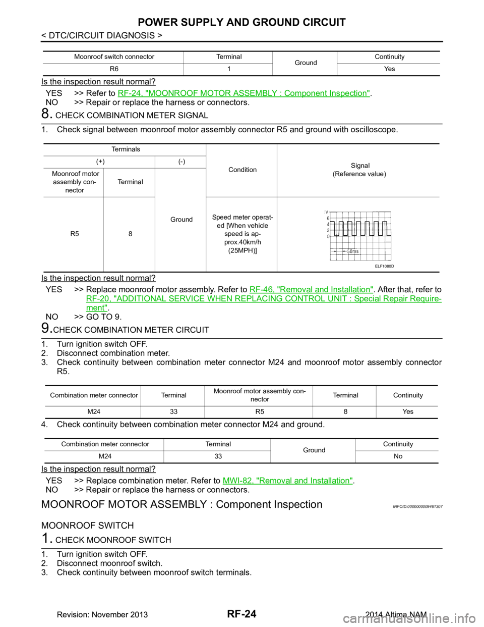
8. CHECK COMBINATION METER SIGNAL
1. Check signal between moonroof motor assembly connector R5 and ground with oscilloscope.
Is the inspection result normal?
YES >> Replace moonroof motor assembly. Refer to RF-46, "Removal and Installation". After that, refer to
RF-20, "ADDITIONAL SERVICE WHEN REPLACING CONTROL UNIT : Special Repair Require-
ment".
NO >> GO TO 9.
9.CHECK COMBINATION METER CIRCUIT
1. Turn ignition switch OFF.
2. Disconnect combination meter.
3. Check continuity between combination meter c onnector M24 and moonroof motor assembly connector
R5.
4. Check continuity between combination meter connector M24 and ground.
Is the inspection result normal?
YES >> Replace combination meter. Refer to MWI-82, "Removal and Installation".
NO >> Repair or replace the harness or connectors.
MOONROOF MOTOR ASSEMBLY : Component InspectionINFOID:0000000009461307
MOONROOF SWITCH
1. CHECK MOONROOF SWITCH
1. Turn ignition switch OFF.
2. Disconnect moonroof switch.
3. Check continuity between moonroof switch terminals.
Moonroof switch connector Terminal GroundContinuity
R6 1 Yes
Te r m i n a l s
Condition Signal
(Reference value)
(+) (-)
Moonroof motor assembly con-
nector Te r m i n a l
Ground
R5 8 Speed meter operat-
ed [When vehicle
speed is ap-
prox.40km/h (25MPH)]
ELF1080D
Combination meter connector Terminal Moonroof motor
assembly con-
nector Terminal Continuity
M24 33 R5 8 Yes
Combination meter connector Terminal GroundContinuity
M24 33 No
Revision: November 20132014 Altima NAMRevision: November 20132014 Altima NAM