Page 970 of 4801
DLK-202
< REMOVAL AND INSTALLATION >
DOOR HANDLE
8. Slide outside handle bracket toward rear of vehicle to remove.: Front
9. Remove clip and disconnect the outside handle cable from the outside handle bracket.
INSTALLATION
Installation in the reverse order of removal.
Tighten rear door outside handle bracket screw to specified torque.
CAUTION:
• When installing do not reuse rear door outside handle bracket screw. Always replace screw with new
ones when removed.
• Check rear door lock cable is proper ly engaged to outside handle bracket.
• After installation, check rear door open/close, lock/unlock operation.
JMKIA5890ZZ
PIIB5815E
Rear door outside handle
bracket screw 5.8 N·m (0.59 kg-m, 51 in-lb)
Revision: November 20132014 Altima NAMRevision: November 20132014 Altima NAM
Page 971 of 4801
DOOR LOCKDLK-203
< REMOVAL AND INSTALLATION >
C
D E
F
G H
I
J
L
M A
B
DLK
N
O P
DOOR LOCK
FRONT DOOR LOCK
FRONT DOOR LOCK : Exploded ViewINFOID:0000000009461949
FRONT DOOR LOCK : Removal and InstallationINFOID:0000000009461950
CAUTION:
Before servicing, turn igni tion switch OFF, disconnect both batt ery terminals and wait at least three
minutes.
REMOVAL
1. Remove the front door outside handle. Refer to DLK-198, "FRONT DOOR HANDLE : Removal and Instal-
lation - Outside Handle".
2. Remove the rear glass run.
3. Disconnect the harness connector from the front door lock actuator.
1. Outside handle escutcheon 2. Rear gasket 3. Screw
4. Door key cylinder rod (driver side) 5. Front door lock assembly 6. Cable clip
7. Inside door handle escutcheon 8. Inside handle 9. Outside handle bracket
10. Front gasket 11. Outside handle 12. Door key cylinder assembly (driv- er side only)
Front
ALKIA2713ZZ
Revision: November 20132014 Altima NAMRevision: November 20132014 Altima NAM
Page 972 of 4801

DLK-204
< REMOVAL AND INSTALLATION >
DOOR LOCK
4. Remove screws, and the door lock assembly.
INSTALLATION
Installation is in the reverse order of removal.
• Tighten front door lock screws to specified torque.
CAUTION:
• Do not reuse inside door handle escutcheon. Replace with new part after removal.
• Do not reuse front door lock assembly screw s. Always replace screws with new ones when
removed.
• Check front door lock cables are properly engage d to inside handle and outside handle bracket.
• When installing door key cylinder rod on the LH front door, be sure to rotate door key cylinder rod
holder until a click is felt.
• After installation, check front doo r open/close, lock/unlock operation.
• Check front door lock assembly for poor lubricatio n. If necessary apply a suitable multi-purpose
grease.
REAR DOOR LOCK
REAR DOOR LOCK : Exploded ViewINFOID:0000000009461951
PIIB5812E
Front door lock screw 5.8 N·m (0.59 kg-m, 51 ft-lb)
ALKIA2714ZZ
Revision: November 20132014 Altima NAMRevision: November 20132014 Altima NAM
Page 973 of 4801

DOOR LOCKDLK-205
< REMOVAL AND INSTALLATION >
C
D E
F
G H
I
J
L
M A
B
DLK
N
O P
REAR DOOR LOCK : Re moval and InstallationINFOID:0000000009461952
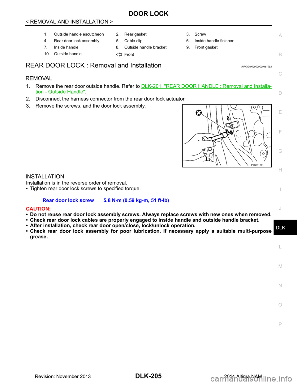
REMOVAL
1. Remove the rear door outside handle. Refer to DLK-201, "REAR DOOR HANDLE : Removal and Installa-
tion - Outside Handle".
2. Disconnect the harness connector from the rear door lock actuator.
3. Remove the screws, and the door lock assembly.
INSTALLATION
Installation is in the reverse order of removal.
• Tighten rear door lock screws to specified torque.
CAUTION:
• Do not reuse rear door lock assembly screws. Always replace screws with new ones when removed.
• Check rear door lock cables are properly engage d to inside handle and outside handle bracket.
• After installation, check rear doo r open/close, lock/unlock operation.
• Check rear door lock assembly for poor lubrication. If necessary apply a suitable multi-purpose
grease.
1. Outside handle escutcheon 2. Rear gasket 3. Screw
4. Rear door lock assembly 5. Cable clip 6. Inside handle finisher
7. Inside handle 8. Outside handle bracket 9. Front gasket
10. Outside handle Front
PIIB5812E
Rear door lock screw 5.8 N·m (0.59 kg-m, 51 ft-lb)
Revision: November 20132014 Altima NAMRevision: November 20132014 Altima NAM
Page 997 of 4801

FRONT DOORDLK-229
< UNIT DISASSEMBLY AND ASSEMBLY >
C
D E
F
G H
I
J
L
M A
B
DLK
N
O P
UNIT DISASSEMBLY AND ASSEMBLY
FRONT DOOR
Exploded ViewINFOID:0000000009461981
Disassembly and AssemblyINFOID:0000000009461982
DISASSEMBLY
NOTE:
RH side shown; LH similar
1. Remove front door. Refer to DLK-184, "DOOR ASSEMBLY : Removal and Installation"
.
2. Remove front door finisher. Refer to INT-15, "Removal and Installation"
.
3. Remove front door lower seal.
4. Remove front door bumper rubber.
5. Remove front door sash molding. Refer to EXT-31, "Removal and Installation"
.
6. Remove front door weatherstrip.
7. Remove front door glass. Refer to GW-14, "Removal and Installation"
.
8. Remove front door glass regulator. Refer to GW-16, "Removal and Installation - Front Regulator"
.
9. Remove front door run rubber. Refer to GW-16, "Exploded View"
.
10. Remove front door outside molding. Refer to EXT-35, "Removal and Installation"
11. Remove front door front and rear glass channel. Refer to GW-16, "Exploded View".
12. Remove front door lock assembly. Refer to DLK-203, "FRONT DOOR LOCK : Removal and Installation"
.
13. Remove front door check link.
1. Front door panel 2. Front door outside molding 3. Front door outer panel
4. Front door tape 5. Front door sash molding 6. Front door check link
7. Front door inside seal 8. Front door lower seal 9. Front door vapor barrier
10. Front door weatherstrip 11. Front door grommet 12. Front door bumper rubber
ALKIA2685ZZ
Revision: November 20132014 Altima NAMRevision: November 20132014 Altima NAM
Page 999 of 4801

REAR DOORDLK-231
< UNIT DISASSEMBLY AND ASSEMBLY >
C
D E
F
G H
I
J
L
M A
B
DLK
N
O P
REAR DOOR
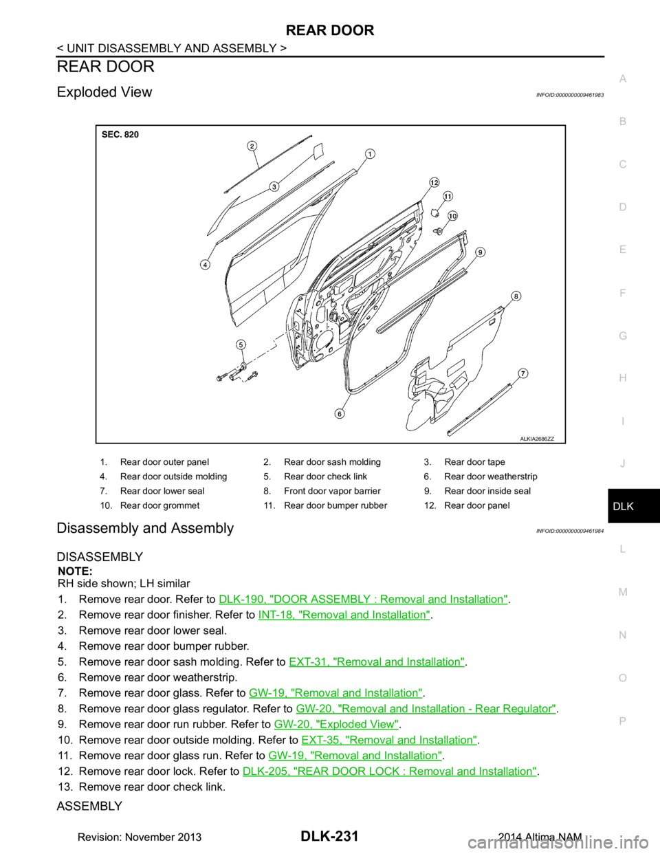
Exploded ViewINFOID:0000000009461983
Disassembly and AssemblyINFOID:0000000009461984
DISASSEMBLY
NOTE:
RH side shown; LH similar
1. Remove rear door. Refer to DLK-190, "DOOR ASSEMBLY : Removal and Installation"
.
2. Remove rear door finisher. Refer to INT-18, "Removal and Installation"
.
3. Remove rear door lower seal.
4. Remove rear door bumper rubber.
5. Remove rear door sash molding. Refer to EXT-31, "Removal and Installation"
.
6. Remove rear door weatherstrip.
7. Remove rear door glass. Refer to GW-19, "Removal and Installation"
.
8. Remove rear door glass regulator. Refer to GW-20, "Removal and Installation - Rear Regulator"
.
9. Remove rear door run rubber. Refer to GW-20, "Exploded View"
.
10. Remove rear door outside molding. Refer to EXT-35, "Removal and Installation"
.
11. Remove rear door glass run. Refer to GW-19, "Removal and Installation"
.
12. Remove rear door lock. Refer to DLK-205, "REAR DOOR LOCK : Removal and Installation"
.
13. Remove rear door check link.
ASSEMBLY
1. Rear door outer panel 2. Rear door sash molding 3. Rear door tape
4. Rear door outside molding 5. Rear door check link 6. Rear door weatherstrip
7. Rear door lower seal 8. Front door vapor barrier 9. Rear door inside seal
10. Rear door grommet 11. Rear door bumper rubber 12. Rear door panel
ALKIA2686ZZ
Revision: November 20132014 Altima NAMRevision: November 20132014 Altima NAM
Page 2283 of 4801

DIAGNOSIS SYSTEM (BCM)EXL-17
< SYSTEM DESCRIPTION >
C
D E
F
G H
I
J
K
M A
B
EXL
N
O P
DIAGNOSIS SYSTEM (BCM)
COMMON ITEM
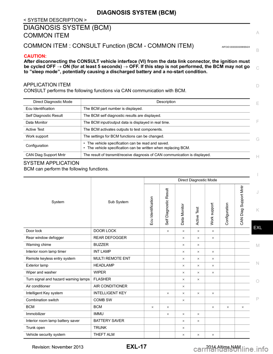
COMMON ITEM : CONSULT Function (BCM - COMMON ITEM)INFOID:0000000009956424
CAUTION:
After disconnecting the CONSULT vehicle interface (VI) from the data link connector, the ignition must
be cycled OFF → ON (for at least 5 seconds) → OFF. If this step is not performed, the BCM may not go
to ”sleep mode”, potentiall y causing a discharged battery and a no-start condition.
APPLICATION ITEM
CONSULT performs the following functions via CAN communication with BCM.
SYSTEM APPLICATION
BCM can perform the following functions.
Direct Diagnostic Mode Description
Ecu Identification The BCM part number is displayed.
Self Diagnostic Result The BCM self diagnostic results are displayed.
Data Monitor The BCM input/output data is displayed in real time.
Active Test The BCM activates outputs to test components.
Work support The settings for BCM functions can be changed.
Configuration • The vehicle specification can be read and saved.
• The vehicle specification can be written when replacing BCM.
CAN Diag Support Mntr The result of transmit/receive diagnosis of CAN communication is displayed.
System Sub System Direct Diagnostic Mode
Ecu Identification
Self Diagnostic Result
Data Monitor
Active Test
Work support
Configuration
CAN Diag Su pport Mntr
Door lock DOOR LOCK ××××
Rear window defogger REAR DEFOGGER ×××
Warning chime BUZZER ××
Interior room lamp timer INT LAMP ×××
Remote keyless entry system MULTI REMOTE ENT ×××
Exterior lamp HEADLAMP ×××
Wiper and washer WIPER ×××
Turn signal and hazard warning lamps FLASHER ××
Air conditioner AIR CONDITIONER ×
Intelligent Key system INTELLIGENT KEY ××××
Combination switch COMB SW ×
BCM BCM × × ×××
Immobilizer IMMU ×××
Interior room lamp battery saver BATTERY SAVER ××
Trunk open TRUNK ×
Vehicle security system THEFT ALM ×××
Revision: November 20132014 Altima NAMRevision: November 20132014 Altima NAM
Page 2285 of 4801

DIAGNOSIS SYSTEM (BCM)EXL-19
< SYSTEM DESCRIPTION >
C
D E
F
G H
I
J
K
M A
B
EXL
N
O P
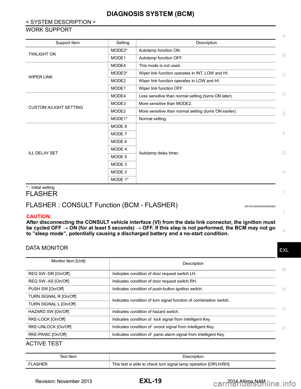
WORK SUPPORT
* : Initial setting
FLASHER
FLASHER : CONSULT Func tion (BCM - FLASHER)INFOID:0000000009956483
CAUTION:
After disconnecting the CONSULT vehicle interface (VI) from the data link connector, the ignition must
be cycled OFF → ON (for at least 5 seconds) → OFF. If this step is not performed, the BCM may not go
to ”sleep mode”, potentiall y causing a discharged battery and a no-start condition.
DATA MONITOR
ACTIVE TEST
Support Item Setting Description
TWILIGHT ON MODE2* Autolamp function ON.
MODE1 Autolamp function OFF.
WIPER LINK MODE4 This mode is not used.
MODE3* Wiper link function operates in INT, LOW and HI.
MODE2 Wiper link function operates in LOW and HI.
MODE1 Wiper link function OFF.
CUSTOM A/LIGHT SETTING MODE4 Less sensitive than normal setting (turns ON later).
MODE3 More sensitive than MODE2.
MODE2 More sensitive than normal setting (turns ON earlier).
MODE1* Normal setting.
ILL DELAY SET MODE 8
Autolamp delay timer.
MODE 7
MODE 6
MODE 4
MODE 5
MODE 3
MODE 2
MODE 1*
Monitor Item [Unit] Description
REQ SW -DR [On/Off] Indicates condition of door request switch LH.
REQ SW -AS [On/Off] Indicates condition of door request switch RH.
PUSH SW [On/Off] Indicates condition of push-button ignition switch.
TURN SIGNAL R [On/Off] Indicates condition of turn signal function of combination switch.
TURN SIGNAL L [On/Off]
HAZARD SW [On/Off] Indicates condition of hazard switch.
RKE-LOCK [On/Off] Indicates condition of lock signal from Intelligent Key.
RKE-UNLOCK [On/Off] Indicates condition of unock signal from Intelligent Key.
RKE-PANIC [On/Off] Indicates condition of panic alarm signal from Intelligent Key.
Test Item Description
FLASHER This test is able to check turn signal lamp operation [Off/LH/RH].
Revision: November 20132014 Altima NAMRevision: November 20132014 Altima NAM