2014 NISSAN TEANA Sec pressure
[x] Cancel search: Sec pressurePage 3198 of 4801
MA-14
< PERIODIC MAINTENANCE >
ENGINE MAINTENANCE (QR25DE)
• Loose connections
• Chafing
• Deterioration
CHECKING RESERVOIR LEVEL
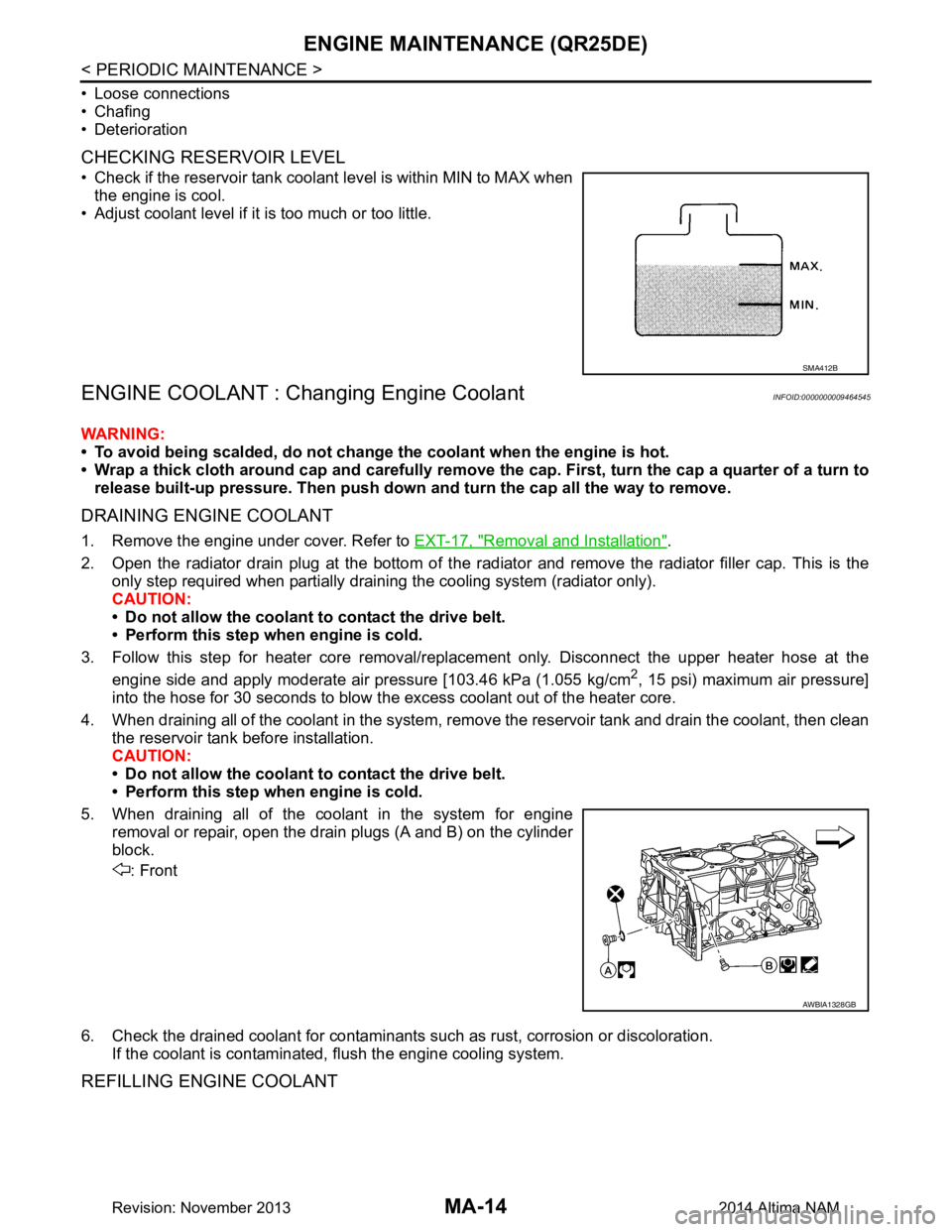
• Check if the reservoir tank coolant level is within MIN to MAX when the engine is cool.
• Adjust coolant level if it is too much or too little.
ENGINE COOLANT : Changing Engine CoolantINFOID:0000000009464545
WARNING:
• To avoid being scalded, do not change the coolant when the engine is hot.
• Wrap a thick cloth around cap and carefully remove the cap. First, turn the cap a quarter of a turn to
release built-up pressure. Then push down and turn the cap all the way to remove.
DRAINING ENGINE COOLANT
1. Remove the engine under cover. Refer to EXT-17, "Removal and Installation".
2. Open the radiator drain plug at the bottom of the radi ator and remove the radiator filler cap. This is the
only step required when partially draining the cooling system (radiator only).
CAUTION:
• Do not allow the coolant to contact the drive belt.
• Perform this step when engine is cold.
3. Follow this step for heater core removal/replac ement only. Disconnect the upper heater hose at the
engine side and apply moderate air pressure [103.46 kPa (1.055 kg/cm
2, 15 psi) maximum air pressure]
into the hose for 30 seconds to blow t he excess coolant out of the heater core.
4. When draining all of the coolant in the system, re move the reservoir tank and drain the coolant, then clean
the reservoir tank before installation.
CAUTION:
• Do not allow the coolant to contact the drive belt.
• Perform this step when engine is cold.
5. When draining all of the coolant in the system for engine removal or repair, open the drain plugs (A and B) on the cylinder
block.
: Front
6. Check the drained coolant for contaminants such as rust, corrosion or discoloration.
If the coolant is contaminated, flush the engine cooling system.
REFILLING ENGINE COOLANT
SMA412B
AWBIA1328GB
Revision: November 20132014 Altima NAM
Page 3205 of 4801
ENGINE MAINTENANCE (QR25DE)MA-21
< PERIODIC MAINTENANCE >
C
D E
F
G H
I
J
K L
M B
MA
N
O A
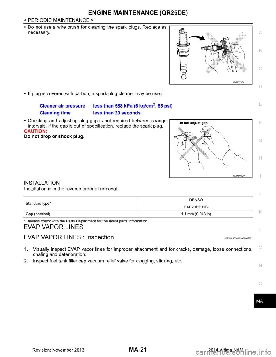
• Do not use a wire brush for cleaning the spark plugs. Replace as
necessary.
• If plug is covered with carbon, a spark plug cleaner may be used.
• Checking and adjusting plug gap is not required between change intervals. If the gap is out of s pecification, replace the spark plug.
CAUTION:
Do not drop or shock plug.
INSTALLATION
Installation is in the reverse order of removal.
*: Always check with the Parts Department for the latest parts information.
EVAP VAPOR LINES
EVAP VAPOR LINES : InspectionINFOID:0000000009464552
1. Visually inspect EVAP vapor lines for improper attachment and for cracks, damage, loose connections,
chafing and deterioration.
2. Inspect fuel tank filler cap vacuum relief valve for clogging, sticking, etc.
SMA773C
Cleaner air pressure : less than 588 kPa (6 kg/cm2, 85 psi)
Cleaning time : less than 20 seconds
SMA806CA
Standard type* DENSO
FXE20HE11C
Gap (nominal) 1.1 mm (0.043 in)
Revision: November 20132014 Altima NAM
Page 3207 of 4801
ENGINE MAINTENANCE (VQ35DE)MA-23
< PERIODIC MAINTENANCE >
C
D E
F
G H
I
J
K L
M B
MA
N
O A
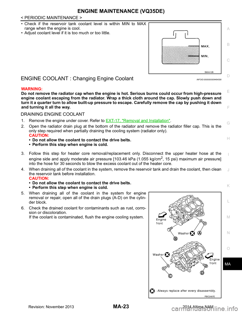
• Check if the reservoir tank coolant level is within MIN to MAX
range when the engine is cool.
• Adjust coolant level if it is too much or too little.
ENGINE COOLANT : Chang ing Engine CoolantINFOID:0000000009464556
WARNING:
Do not remove the radiator cap when the engine is hot. Serious burns could occur from high-pressure
engine coolant escaping from the radiator. Wrap a thick cloth around the cap. Slowly push down and
turn it a quarter turn to allow built-up pressure to escape. Carefully remove the cap by pushing it down
and turning it all the way.
DRAINING ENGINE COOLANT
1. Remove the engine under cover. Refer to EXT-17, "Removal and Installation".
2. Open the radiator drain plug at the bottom of the radiat or and remove the radiator filler cap. This is the
only step required when partially draining the cooling system (radiator only).
CAUTION:
• Do not allow the coolant to contact the drive belts.
• Perform this step when engine is cold.
3. Follow this step for heater core removal/repl acement only. Disconnect the upper heater hose at the
engine side and apply moderate air pressure [103.46 kPa (1.055 kg/cm
2, 15 psi) maximum air pressure]
into the hose for 30 seconds to blow the excess coolant out of the heater core.
4. When draining all of the coolant in the system, remo ve the reservoir tank and drain the coolant, then clean
the reservoir tank before installation.
CAUTION:
• Do not allow the coolant to contact the drive belts.
• Perform this step when engine is cold.
5. When draining all of the coolant in the system for engine removal or repair, open all of the drain plugs (A-D) on the cylin-
der block.
6. Check the drained coolant for contaminants such as rust, corro- sion or discoloration.
If the coolant is contaminated, flush the engine cooling system.
SMA412B
PBIC2487E
Revision: November 20132014 Altima NAM
Page 3214 of 4801
MA-30
< PERIODIC MAINTENANCE >
ENGINE MAINTENANCE (VQ35DE)
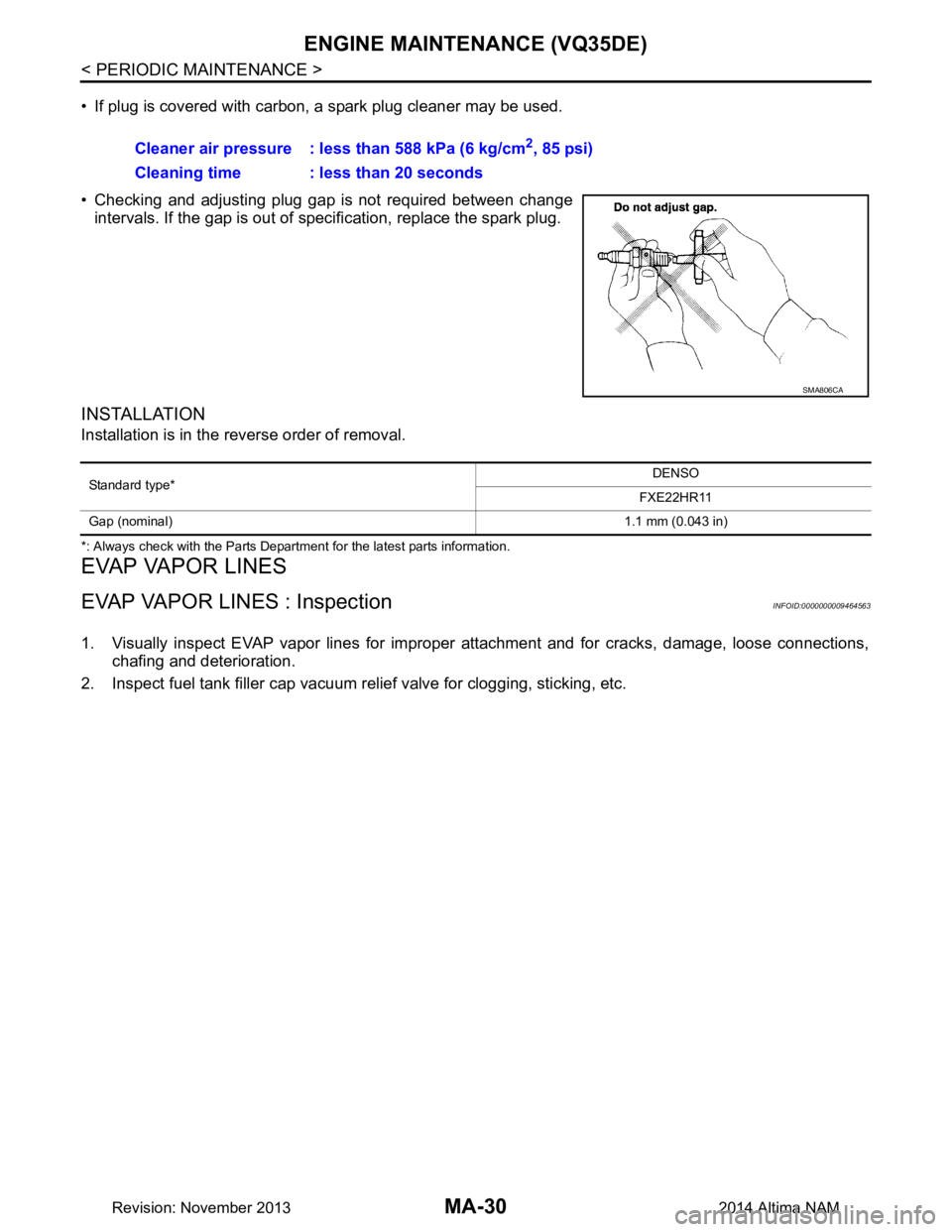
• If plug is covered with carbon, a spark plug cleaner may be used.
• Checking and adjusting plug gap is not required between change intervals. If the gap is out of s pecification, replace the spark plug.
INSTALLATION
Installation is in the reverse order of removal.
*: Always check with the Parts Department for the latest parts information.
EVAP VAPOR LINES
EVAP VAPOR LINES : InspectionINFOID:0000000009464563
1. Visually inspect EVAP vapor lines for improper attachment and for cracks, damage, loose connections,
chafing and deterioration.
2. Inspect fuel tank filler cap vacuum relief valve for clogging, sticking, etc. Cleaner air pressure : less than 588 kPa (6 kg/cm
2, 85 psi)
Cleaning time : less than 20 seconds
SMA806CA
Standard type* DENSO
FXE22HR11
Gap (nominal) 1.1 mm (0.043 in)
Revision: November 20132014 Altima NAM
Page 3266 of 4801
MWI
SYSTEMMWI-11
< SYSTEM DESCRIPTION >
C
D E
F
G H
I
J
K L
M B
A
O P
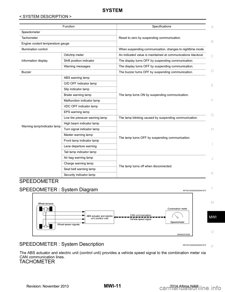
SPEEDOMETER
SPEEDOMETER : System DiagramINFOID:0000000009461675
SPEEDOMETER : System DescriptionINFOID:0000000009461676
The ABS actuator and electric unit (control unit) provi des a vehicle speed signal to the combination meter via
CAN communication lines.
TACHOMETER
Function Specifications
Speedometer Reset to zero by suspending communication.
Tachometer
Engine coolant temperature gauge
Illumination control When suspending communication, changes to nighttime mode.
Information display Odo/trip meter An indicated value is maintained at communications blackout.
Shift position indicator The display turns OFF by suspending communication.
Warning messages The display turns OFF by suspending communication.
Buzzer The buzzer turns OFF by suspending communication.
Warning lamp/indicator lamp ABS warning lamp
The lamp turns ON by suspending communication.
O/D OFF indicator lamp
Slip indicator lamp
Brake warning lamp
Malfunction indicator lamp
VDC OFF indicator lamp
EPS warning lamp
Low tire pressure warning lamp The lamp blinking caused by suspending communication.
High beam indicator lamp
The lamp turns OFF by suspending communication.
Turn signal indicator lamp
Master warning lamp
Front lamp indicator lamp
Lane departure warning
Tail lamp indicator lamp
Air bag warning lamp
The lamp turns off when disconnected.
Charge warning lamp
Seat belt warning lamp
Security indicator lamp
AWNIA2379GB
Revision: November 20132014 Altima NAMRevision: November 20132014 Altima NAM
Page 3282 of 4801

MWI
COMBINATION METERMWI-27
< ECU DIAGNOSIS INFORMATION >
C
D E
F
G H
I
J
K L
M B
A
O PFail-SafeINFOID:0000000009461695
FA I L - S A F E
The combination meter activates the fail-safe contro l if CAN communication with each unit is malfunctioning.
DTC IndexINFOID:0000000009461696
52
(P) Ground O/D OFF/SPORT switch Input Ignition
switch
ON O/D OFF switch pressed 0 V
Other than the above 5 V
Te r m i n a l N o .
(Wire color) Description
ConditionVa l u e
(Approx.)
+ – Signal name Input/
Output
Function Specifications
Speedometer Reset to zero by suspending communication.
Tachometer
Engine coolant temperature gauge
Illumination control When suspending communication, changes to nighttime mode.
Information display Odo/trip meter An indicated value is maintained at communications blackout.
Shift position indicator The display turns OFF by suspending communication.
Warning messages The display turns OFF by suspending communication.
Buzzer The buzzer turns OFF by suspending communication.
Warning lamp/indicator lamp ABS warning lamp
The lamp turns ON by suspending communication.
O/D OFF indicator lamp
Slip indicator lamp
Brake warning lamp
Malfunction indicator lamp
VDC OFF indicator lamp
EPS warning lamp
Low tire pressure warning lamp The lamp blinking caused by suspending communication.
High beam indicator lamp
The lamp turns OFF by suspending communication.
Turn signal indicator lamp
Master warning lamp
Front lamp indicator lamp
Lane departure warning
Tail lamp indicator lamp
Air bag warning lamp
The lamp turns off when disconnected.
Charge warning lamp
Seat belt warning lamp
Security indicator lamp
Display contents of CONSULT Diagnostic item is detected when... Refer to
CAN COMM CIRCUIT
[U1000] When combination meter is not transmitting or receiving CAN communication signal for 2
seconds or more. MWI-53
CONTROL UNIT (CAN)
[U1010] When detecting error during the initial diagnosis of the CAN controller of combination
meter. MWI-54
Revision: November 20132014 Altima NAMRevision: November 20132014 Altima NAM
Page 3388 of 4801
![NISSAN TEANA 2014 Service Manual
PCS
DIAGNOSIS SYSTEM (BCM)PCS-39
< SYSTEM DESCRIPTION > [POWER DISTRIBUTION SYSTEM]
C
D E
F
G H
I
J
K L
B
A
O P
N
INTELLIGENT KEY
INTELLIGENT KEY : CONSULT Func
tion (BCM - INTELLIGENT KEY)INFOID:0 NISSAN TEANA 2014 Service Manual
PCS
DIAGNOSIS SYSTEM (BCM)PCS-39
< SYSTEM DESCRIPTION > [POWER DISTRIBUTION SYSTEM]
C
D E
F
G H
I
J
K L
B
A
O P
N
INTELLIGENT KEY
INTELLIGENT KEY : CONSULT Func
tion (BCM - INTELLIGENT KEY)INFOID:0](/manual-img/5/57390/w960_57390-3387.png)
PCS
DIAGNOSIS SYSTEM (BCM)PCS-39
< SYSTEM DESCRIPTION > [POWER DISTRIBUTION SYSTEM]
C
D E
F
G H
I
J
K L
B
A
O P
N
INTELLIGENT KEY
INTELLIGENT KEY : CONSULT Func
tion (BCM - INTELLIGENT KEY)INFOID:0000000009941331
CAUTION:
After disconnecting the CONSULT vehicle interface (VI) from the data link connector, the ignition must
be cycled OFF → ON (for at least 5 seconds) → OFF. If this step is not performed, the BCM may not go
to ”sleep mode”, potentiall y causing a discharged battery and a no-start condition.
SELF DIAGNOSTIC RESULT
Refer to BCS-52, "DTC Index".
DATA MONITOR
RAP system RETAINED PWR ×
Signal buffer system SIGNAL BUFFER ×
TPMS AIR PRESSURE MONITOR ××××
System Sub System
Direct Diagnostic Mode
Ecu Identification
Self Diagnostic Result
Data Monitor
Active Test
Work support
Configuration
CAN Diag Support Mntr
Monitor Item [Unit] Main Description
REQ SW -DR [On/Off] ×Indicates condition of door request switch LH.
REQ SW -AS [On/Off] ×Indicates condition of door request switch RH.
REQ SW -BD/TR [On/Off] ×Indicates condition of trunk opener request switch.
PUSH SW [On/Off] Indicates condition of push-button ignition switch.
SHFTLCK SLNID PER SPLY [On/Off] ×Indicates condition of power supply to shiftlock solenoid.
BRAKE SW 1 [On/Off] ×Indicates condition of brake switch.
BRAKE SW 2 [On/Off] Indicates condition of brake switch.
DETE/CANCL SW [On/Off] ×Indicates condition of P (park) position.
SFT PN/N SW [On/Off] ×Indicates condition of P (park) or N (neutral) position.
UNLK SEN -DR [On/Off] ×Indicates condition of door unlock sensor.
PUSH SW -IPDM [On/Off] Indicates condition of push-button ignition switch received from IPDM E/R
on CAN communication line.
IGN RLY1 -F/B [On/Off] Indicates condition of ignition relay 1 received from IPDM E/R on CAN
communication line.
DETE SW -IPDM [On/Off] Indicates condition of detent switch received from TCM on CAN communi-
cation line.
SFT PN -IPDM [On/Off] Indicates condition of P (park) or N (neutral) position from TCM on CAN
communication line.
SFT P -MET [On/Off] Indicates condition of P (park) position from TCM on CAN communication
line.
SFT N -MET [On/Off] Indicates condition of N (neutral) position from IPDM E/R on CAN commu-
nication line.
ENGINE STATE [STOP/START/CRANK/RUN] ×Indicates condition of engine state from ECM on CAN communication line.
VEH SPEED 1 [mph/km/h] ×Indicates condition of vehicle speed signal received from ABS on CAN
communication line.
Revision: November 20132014 Altima NAMRevision: November 20132014 Altima NAM
Page 3521 of 4801
![NISSAN TEANA 2014 Service Manual
PWC-14
< SYSTEM DESCRIPTION >[LH FRONT ONLY ANTI-PINCH]
DIAGNOSIS SYSTEM (BCM)
RETAINED PWR
RETAINED PWR : CONSULT Function (BCM - RETAINED PWR)INFOID:0000000009955264
CAUTION:
After disconnecting t NISSAN TEANA 2014 Service Manual
PWC-14
< SYSTEM DESCRIPTION >[LH FRONT ONLY ANTI-PINCH]
DIAGNOSIS SYSTEM (BCM)
RETAINED PWR
RETAINED PWR : CONSULT Function (BCM - RETAINED PWR)INFOID:0000000009955264
CAUTION:
After disconnecting t](/manual-img/5/57390/w960_57390-3520.png)
PWC-14
< SYSTEM DESCRIPTION >[LH FRONT ONLY ANTI-PINCH]
DIAGNOSIS SYSTEM (BCM)
RETAINED PWR
RETAINED PWR : CONSULT Function (BCM - RETAINED PWR)INFOID:0000000009955264
CAUTION:
After disconnecting the CONSULT vehicle interface (VI) from the data link connector, the ignition must
be cycled OFF → ON (for at least 5 seconds) → OFF. If this step is not performed, the BCM may not go
to ”sleep mode”, potentially causing a di scharged battery and a no-start condition.
DATA MONITOR
RAP system RETAINED PWR ×
Signal buffer system SIGNAL BUFFER ×
TPMS AIR PRESSURE MONITOR ××××
System Sub System
Direct Diagnostic Mode
Ecu Identification
Self Diagnostic Result
Data Monitor
Active Test
Work support
Configuration
CAN Diag Support Mntr
Monitor Item [Unit] Description
DOOR SW-DR [On/Off] Indicates condition of front door switch LH.
DOOR SW-AS [On/Off] Indicates condition of front door switch RH.
Revision: November 20132014 Altima NAMRevision: November 20132014 Altima NAM