2014 NISSAN TEANA Sec pressure
[x] Cancel search: Sec pressurePage 2220 of 4801
![NISSAN TEANA 2014 Service Manual
EM-222
< UNIT REMOVAL AND INSTALLATION >[VQ35DE]
ENGINE ASSEMBLY
• (B): LH cylinder head
25. Remove rear cover plate.
26. Remove the torque converter nuts.
27. Remove nuts of stabilizer connectin NISSAN TEANA 2014 Service Manual
EM-222
< UNIT REMOVAL AND INSTALLATION >[VQ35DE]
ENGINE ASSEMBLY
• (B): LH cylinder head
25. Remove rear cover plate.
26. Remove the torque converter nuts.
27. Remove nuts of stabilizer connectin](/manual-img/5/57390/w960_57390-2219.png)
EM-222
< UNIT REMOVAL AND INSTALLATION >[VQ35DE]
ENGINE ASSEMBLY
• (B): LH cylinder head
25. Remove rear cover plate.
26. Remove the torque converter nuts.
27. Remove nuts of stabilizer connecting rods from struts. Refer to FSU-19, "Exploded View"
.
28. Remove front wheel speed sensors and position aside. Refer to BRC-124, "Removal and Installation -
Front Wheel Sensor".
29. Remove front brake rotors. Refer to BR-36, "BRAKE CALIPER ASSEMBLY : Removal and Installation"
.
30. Remove piston rod nut. Refer to FSU-19, "Exploded View"
.
31. Remove front drive shaft (LH/RH). Refer to FAX-10, "Removal and Installation (LH)"
and FAX-12,
"Removal and Installation (RH)".
32. Remove RH drive shaft center bearing bracket.
33. Remove lower steering column pinch bolt. Refer to ST-33, "Exploded View"
.
34. Remove three way catalyst (manifold) (bank 1) heat shield.
35. Disconnect front and rear engine mounting insulator vacuum hoses.
36. Remove front and rear engine mounting insulator nut.
37. Position a suitable support table under suspension member and engine assembly. TM-206, "Removal and
Installation"
38. Disconnect the engine mounting insulator (LH), upper torque rod, and engine mounting insulator (RH).
39. For additional safety, secure the engine in position with suitable tool.
40. Remove suspension member bolts. Refer to FSU-19, "Exploded View"
.
41. Carefully lower the engine, transaxle assembly and suspension member using Tool, avoiding interference
with the vehicle body.
CAUTION:
• Before and during this procedure, alw ays check if any harnesses are left connected.
• Avoid any damage to, or any oil/grease smearin g or spilling onto the engine mounting insula-
tors.
42. Remove the starter motor. Refer to STR-23, "VQ35DE : Removal and Installation"
.
43. Remove the crankshaft position sensor (POS).
44. Remove engine and transaxle harness.
45. Separate the engine and transaxle and mount the engine on a suitable engine stand.
INSTALLATION
Installation is in the reverse order of removal.
NOTE:
Tighten transmission bolts to specification. Refer to TM-206, "Removal and Installation"
.
INSPECTION AFTER INSTALLATION
• Before starting engine, check oil/fluid levels including engine coolant and engine oil. If less than required
quantity, fill to the specified level. Refer to MA-11, "FOR USA AND CANADA : Fluids and Lubricants"
.
• Use procedure below to check for fuel leakage.
• Turn ignition switch ON (with engine stopped). With fuel pressure applied to fuel piping, check for fuel leak-
age at connection points.
ALBIA0263GB
Tool number : KV101J0010 (J-47242)
Revision: November 20132014 Altima NAM
Page 2284 of 4801
EXL-18
< SYSTEM DESCRIPTION >
DIAGNOSIS SYSTEM (BCM)
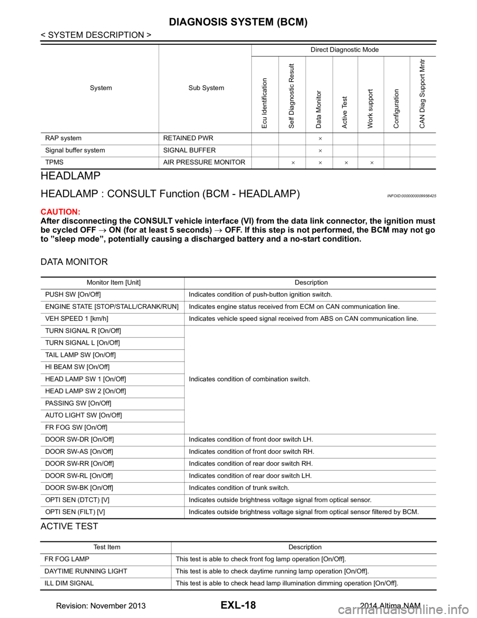
HEADLAMP
HEADLAMP : CONSULT Function (BCM - HEADLAMP)INFOID:0000000009956425
CAUTION:
After disconnecting the CONSULT vehicle interface (VI) from the data link connector, the ignition must
be cycled OFF → ON (for at least 5 seconds) → OFF. If this step is not performed, the BCM may not go
to ”sleep mode”, potentially causing a di scharged battery and a no-start condition.
DATA MONITOR
ACTIVE TEST
RAP system RETAINED PWR ×
Signal buffer system SIGNAL BUFFER ×
TPMS AIR PRESSURE MONITOR ××××
System Sub System
Direct Diagnostic Mode
Ecu Identification
Self Diagnostic Result
Data Monitor
Active Test
Work support
Configuration
CAN Diag Support Mntr
Monitor Item [Unit] Description
PUSH SW [On/Off] Indicates condition of push-button ignition switch.
ENGINE STATE [STOP/STALL/CRANK/RUN] Indicates engine st atus received from ECM on CAN communication line.
VEH SPEED 1 [km/h] Indicates vehicle speed signal received from ABS on CAN communication line.
TURN SIGNAL R [On/Off]
Indicates condition of combination switch.
TURN SIGNAL L [On/Off]
TAIL LAMP SW [On/Off]
HI BEAM SW [On/Off]
HEAD LAMP SW 1 [On/Off]
HEAD LAMP SW 2 [On/Off]
PASSING SW [On/Off]
AUTO LIGHT SW [On/Off]
FR FOG SW [On/Off]
DOOR SW-DR [On/Off] Indicates condition of front door switch LH.
DOOR SW-AS [On/Off] Indicates condition of front door switch RH.
DOOR SW-RR [On/Off] Indicates condition of rear door switch RH.
DOOR SW-RL [On/Off] Indicates condition of rear door switch LH.
DOOR SW-BK [On/Off] Indicates condition of trunk switch.
OPTI SEN (DTCT) [V] Indicates outside brightness voltage signal from optical sensor.
OPTI SEN (FILT) [V] Indicates outside brightness voltage signal from optical sensor filtered by BCM.
Test Item Description
FR FOG LAMP This test is able to check front fog lamp operation [On/Off].
DAYTIME RUNNING LIGHT This test is able to check daytime running la mp operation [On/Off].
ILL DIM SIGNAL This test is able to check head lamp illumination dimming operation [On/Off].
Revision: November 20132014 Altima NAMRevision: November 20132014 Altima NAM
Page 2481 of 4801

FL-1
ENGINE
C
D E
F
G H
I
J
K L
M
SECTION FL
A
FL
N
O P
CONTENTS
FUEL SYSTEM
PRECAUTION ................ ...............................2
PRECAUTIONS .............................................. .....2
Precaution for Supplemental Restraint System
(SRS) "AIR BAG" and "SEAT BELT PRE-TEN-
SIONER" ............................................................. ......
2
General Precaution ...................................................2
PREPARATION ............................................4
PREPARATION .............................................. .....4
Special Service Tool ........................................... ......4
Commercial Service Tool ..........................................4
PERIODIC MAINTENANCE ..........................5
FUEL SYSTEM ............................................... .....5
Inspection ............................................................ ......5
Quick Connector .......................................................5
REMOVAL AND INSTALLATION ................6
FUEL LEVEL SENSOR UNIT, FUEL FILTER
AND FUEL PUMP ASSEMBLY ..................... .....
6
Exploded View .................................................... ......6
Removal and Installation ...........................................6
Inspection ............................................................ ......9
FUEL TANK ........................................................10
Exploded View .................................................... ....10
Removal and Installation .........................................10
Inspection ............................................................ ....13
EVAP CANISTER ..............................................14
Exploded View .........................................................14
Removal and Installation .........................................14
Inspection ................................................................15
EVAP CANISTER FILTER ................................16
Exploded View .........................................................16
Removal and Installation .........................................16
EVAP CANISTER VENT CONTROL VALVE ...17
Exploded View .........................................................17
Removal and Installation .........................................17
EVAP CONTROL SYSTEM PRESSURE SEN-
SOR ...................................................................
18
Exploded View ..................................................... ....18
Removal and Installation .........................................18
UNIT DISASSEMBLY AND ASSEMBLY ....19
FUEL LEVEL SENSOR UNIT ...........................19
Disassembly and Assembly ................................. ....19
SERVICE DATA AND SPECIFICATIONS
(SDS) ............... .............................................
21
SERVICE DATA AND SPECIFICATIONS
(SDS) .................................................................
21
Fuel Tank ............................................................. ....21
Revision: November 20132014 Altima NAM
Page 2482 of 4801
FL-2
< PRECAUTION >
PRECAUTIONS
PRECAUTION
PRECAUTIONS
Precaution for Supplemental Restraint System (SRS) "AIR BAG" and "SEAT BELT
PRE-TENSIONER"
INFOID:0000000009951691
The Supplemental Restraint System such as “A IR BAG” and “SEAT BELT PRE-TENSIONER”, used along
with a front seat belt, helps to reduce the risk or severi ty of injury to the driver and front passenger for certain
types of collision. Information necessary to service the system safely is included in the SR and SB section of
this Service Manual.
WARNING:
• To avoid rendering the SRS inopera tive, which could increase the risk of personal injury or death in
the event of a collision which would result in air bag inflation, all maintenance must be performed by
an authorized NISS AN/INFINITI dealer.
• Improper maintenance, including in correct removal and installation of the SRS, can lead to personal
injury caused by unintent ional activation of the system. For re moval of Spiral Cable and Air Bag
Module, see the SR section.
• Do not use electrical test equipmen t on any circuit related to the SRS unless instructed to in this
Service Manual. SRS wiring harn esses can be identified by yellow and/or orange harnesses or har-
ness connectors.
PRECAUTIONS WHEN USING POWER TOOLS (AIR OR ELECTRIC) AND HAMMERS
WARNING:
• When working near the Airbag Diagnosis Sensor Unit or other Airbag System sensors with the Igni-
tion ON or engine running, DO NOT use air or electri c power tools or strike near the sensor(s) with a
hammer. Heavy vibration could activate the sensor( s) and deploy the air bag(s), possibly causing
serious injury.
• When using air or electric power tools or hammers , always switch the Ignition OFF, disconnect the
battery and wait at least three minutes before performing any service.
General PrecautionINFOID:0000000009460597
WARNING:
When replacing fuel line parts, be sure to observe the following.
• Put a “CAUTION: FLAMMABLE” sign in the work area.
• Be sure to work in a well ventilated area and have a CO
2 fire extinguisher.
• Do not smoke while working on the fuel system. Keep open flames and sparks away from the work
area.
CAUTION:
• Before removing fuel line parts, carry out the following procedures:
- Put drained fuel in an explosi on-proof container and put the lid on securely. Keep the container in
safe area.
- Release fuel pressure from the fuel lines. Refer to EC-182, "Work Procedure"
(QR25DE), EC-687,
"Work Procedure" (VQ35DE).
- Disconnect the battery ground cable.
• Always replace O-rings and clamps with new ones.
• Do not kink or twist tubes when they are being installed.
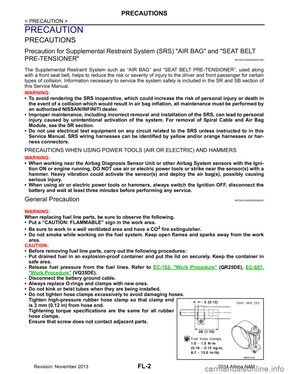
• Do not tighten hose clamps excessi vely to avoid damaging hoses.
Tighten high-pressure rubber hose clamp so that clamp end
is 3 mm (0.12 in) from hose end.
Tightening torque specificati ons are the same for all rubber
hose clamps.
Ensure that screw does not contact adjacent parts.
MMA104A
Revision: November 20132014 Altima NAM
Page 2483 of 4801
PRECAUTIONSFL-3
< PRECAUTION >
C
D E
F
G H
I
J
K L
M A
FL
NP
O
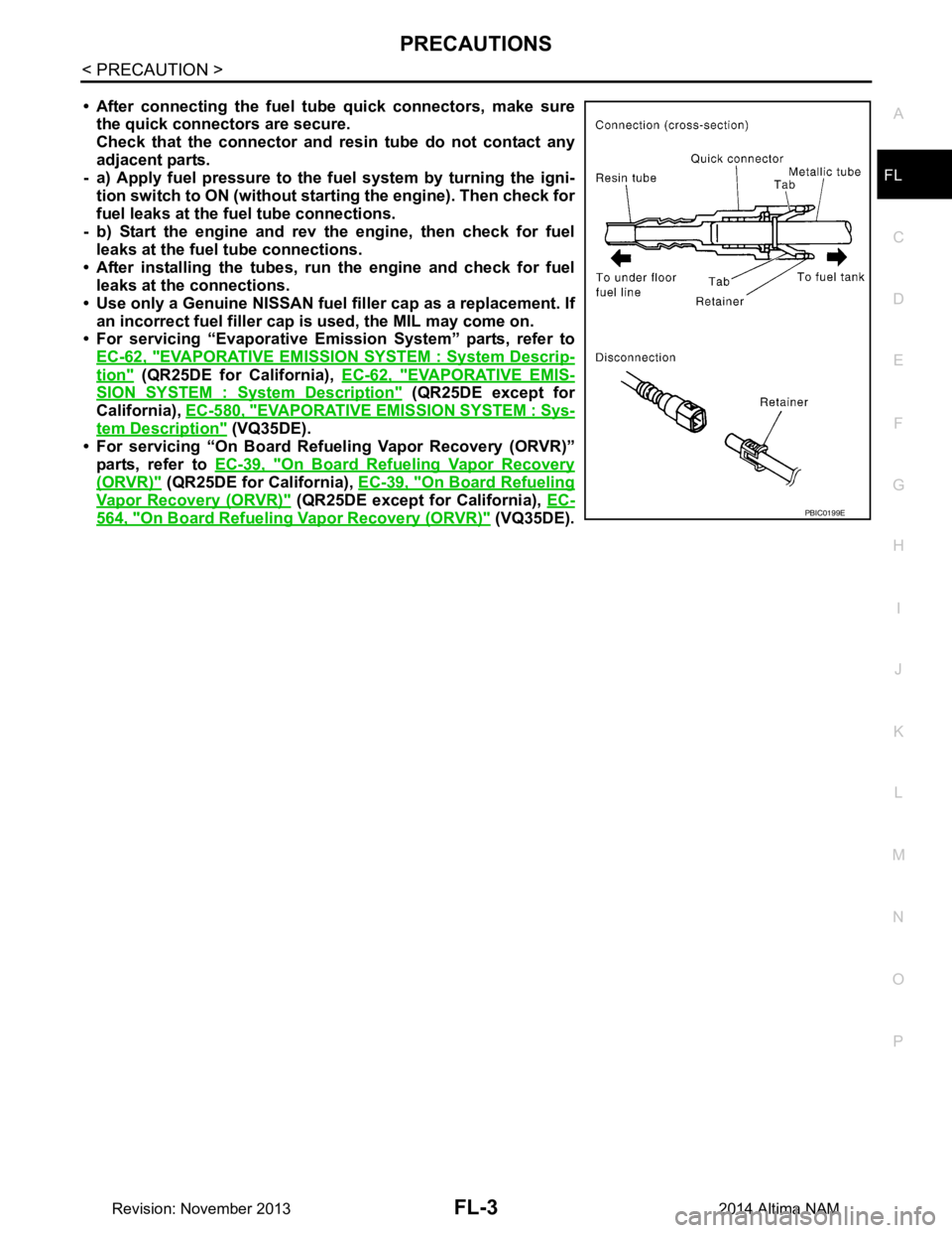
• After connecting the fuel tu
be quick connectors, make sure
the quick connectors are secure.
Check that the connector and r esin tube do not contact any
adjacent parts.
- a) Apply fuel pressure to the fu el system by turning the igni-
tion switch to ON (without star ting the engine). Then check for
fuel leaks at the fuel tube connections.
- b) Start the engine and rev the engine, then check for fuel leaks at the fuel tube connections.
• After installing the tubes, run the engine and check for fuel
leaks at the connections.
• Use only a Genuine NISSAN fuel filler cap as a replacement. If
an incorrect fuel fi ller cap is used, the MIL may come on.
• For servicing “Evaporative Emi ssion System” parts, refer to
EC-62, "EVAPORATIVE EMISSI ON SYSTEM : System Descrip-
tion" (QR25DE for California), EC-62, "EVAPORATIVE EMIS-
SION SYSTEM : System Description" (QR25DE except for
California), EC-580, "EVAPORATIVE EM ISSION SYSTEM : Sys-
tem Description" (VQ35DE).
• For servicing “On Board Refuel ing Vapor Recovery (ORVR)”
parts, refer to EC-39, "On Board Refueling Vapor Recovery
(ORVR)" (QR25DE for California), EC-39, "On Board Refueling
Vapor Recovery (ORVR)" (QR25DE except for California), EC-
564, "On Board Refueling Vapor Recovery (ORVR)" (VQ35DE).PBIC0199E
Revision: November 20132014 Altima NAM
Page 2541 of 4801

ABBREVIATIONSGI-13
< HOW TO USE THIS MANUAL >
C
D E
F
G H
I
J
K L
M B
GI
N
O PABBREVIATIONS
Abbreviation ListINFOID:0000000009462979
The following ABBREVIATIONS are used:
A
B
C
D
ABBREVIATION DESCRIPTION A/C Air conditioner
A/C Air conditioning
A/F sensor Air fuel ratio sensor A/T Automatic transaxle/transmission
ABS Anti-lock braking system
ACCS Advance climate control system ACL Air cleaner
AP Accelerator pedal
APP Accelerator pedal position AV Audio visual
AVM Around view monitor
AWD All wheel drive
ABBREVIATION DESCRIPTION BARO Barometric pressureBCI Backup collision intervention
BCM Body control module
BLSD Brake limited slip differential BPP Brake pedal positionBSI Blind spot intervention
BSW Blind spot warning
ABBREVIATION DESCRIPTION CKP Crankshaft positionCL Closed loop
CMP Camshaft position CPP Clutch pedal positionCTP Closed throttle position
CVT Continuously variable transaxle/transmission
ABBREVIATION DESCRIPTION D
1Drive range first gear
D
2Drive range second gear
D
3Drive range third gear
D
4Drive range fourth gear
DCA Distance control assist
DDS Downhill drive support DFI Direct fuel injection system
DLC Data link connector
DTC Diagnostic trouble code
Revision: November 20132014 Altima NAMRevision: November 20132014 Altima NAM
Page 2557 of 4801
PRECAUTIONSGI-29
< PRECAUTION >
C
D E
F
G H
I
J
K L
M B
GI
N
O P
To prevent ECM from storing the diagnostic trou ble codes, do not carelessly disconnect the harness
connectors which are related to the engine cont rol system and TCM (transmission control module)
system. The connectors should be disconnected only when working according to the WORK FLOW of
TROUBLE DIAGNOSES in EC and TM sections.
Three Way CatalystINFOID:0000000009462996
If a large amount of unburned fuel flows into the catalyst , the catalyst temperature will be excessively high. To
prevent this, follow the instructions.
• Use unleaded gasoline only. Leaded gasoline will seriously damage the three way catalyst.
• When checking for ignition spark or measuring engine compression, make tests quickly and only when nec- essary.
• Do not run engine when the fuel tank level is low, otherwise the engine may misfire, causing damage to the
catalyst.
Do not place the vehicle on flammable material. Keep flammable material off the exhaust pipe and the three
way catalyst.
Fuel (Regular Unleaded Ga soline Recommended) QR25DEINFOID:0000000009462997
Use unleaded regular gasoline with an octane rating of at least 87 AKI (Anti-Knock Index) number (Research
octane number 91). E-85 fuel (85% fuel ethanol, 15% unl eaded gasoline) may only be used in vehicles specif-
ically designed for E-85 fuel (i.e. Flexible Fuel Vehicle - FFV models).
CAUTION:
Do not use leaded gasoli ne. Using leaded gasoline will damage the three way catalyst. Do not use E-85
fuel (85% fuel ethanol, 15% unlead ed gasoline) unless the vehicle is specifically designed for E-85 fuel
(i.e. Flexible Fuel Vehicle - FFV models). Using a fu el other than that specified could adversely affect
the emission control devices and systems, and could also affect the warranty coverage validity.
Fuel (Regular Unleaded Gasoline Recommended) VQ35DEINFOID:0000000009462998
Use unleaded regular gasoline with an octane rating of at least 87 AKI (Anti-Knock Index) number (Research
octane number 91). E-85 fuel (85% fuel ethanol, 15% unl eaded gasoline) may only be used in vehicles specif-
ically designed for E-85 fuel (i.e. Flexible Fuel Vehicle - FFV models).
CAUTION:
Do not use leaded gasoli ne. Using leaded gasoline will damage the three way catalyst. Do not use E-85
fuel (85% fuel ethanol, 15% unlead ed gasoline) unless the vehicle is specifically designed for E-85 fuel
(i.e. Flexible Fuel Vehicle - FFV models). Using a fu el other than that specified could adversely affect
the emission control devices and systems, and could also affect the warranty coverage validity.
Multiport Fuel Injection System or Engine Control SystemINFOID:0000000009462999
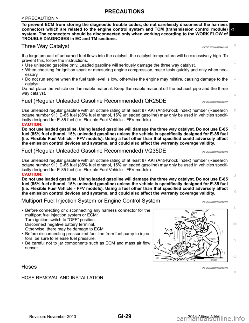
• Before connecting or disconnecti ng any harness connector for the
multiport fuel injection system or ECM:
Turn ignition switch to “OFF” position.
Disconnect negative battery terminal.
Otherwise, there may be damage to ECM.
• Before disconnecting pressurized fuel line from fuel pump to injec-
tors, be sure to release fuel pressure.
• Be careful not to jar components such as ECM and mass air flow sensor.
HosesINFOID:0000000009463000
HOSE REMOVAL AND INSTALLATION
SGI787
Revision: November 20132014 Altima NAMRevision: November 20132014 Altima NAM
Page 2592 of 4801
GW-12
< REMOVAL AND INSTALLATION >
WINDSHIELD GLASS
Removal and Installation
INFOID:0000000009463661
REMOVAL
1. Partially remove the headlining (front edge). Refer to INT-30, "Removal and Installation".
2. Remove inside mirror. Refer to MIR-19, "Removal and Installation"
.
3. Remove the cowl top cover. Refer to EXT-24, "Removal and Installation"
.
4. Remove roof side moldings (LH/RH). Refer to EXT-36, "Removal and Installation"
.
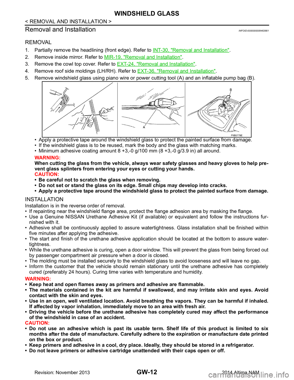
5. Remove windshield glass using piano wire or pow er cutting tool (A) and an inflatable pump bag (B).
• Apply a protective tape around the windshield gla ss to protect the painted surface from damage.
• If the windshield glass is to be reused, mark the body and the glass with matching marks.
• Minimum adhesive coating amount 8 +3,- 0 g/100 mm (8 +3,-0 g/3.9 in) all around.
WARNING:
When cutting the glass from the vehicle, always wear safety glasses and heavy gloves to help pre-
vent glass splinters from entering your eyes or cutting your hands.
CAUTION:
• Be careful not to scratch the glass when removing.
• Do not set or stand the glass on its ed ge. Small chips may develop into cracks.
• Apply a protective tape around the windshield glass to protect the painted surface from damage.
INSTALLATION
Installation is in the reverse order of removal.
• If repainting near the windshield flange area, pr otect the flange adhesion area by masking the flange.
• Use a Genuine NISSAN Urethane Adhesive Kit (if availabl e) or equivalent and follow the instructions fur-
nished with it.
• Adhesive shall be continuously applied to assure watert ightness. Glass installation shall be finished within
five minutes after applying the adhesive.
• The start and finish of the urethane adhesive application should be located at the bottom to assure water-
tightness.
• While the urethane adhesive is curing, open a door window . This will prevent the glass from being forced out
by passenger compartment air pressure when a door is closed.
• The molding must be installed securely to the windshield glass to avoid looseness and will leave no gap.
• Inform the customer that the vehicle should rema in stationary until the urethane adhesive has completely
cured (preferably 24 hours). Curing time varies with temperature and humidity.
WARNING:
• Keep heat and open flames away as primers and adhesive are flammable.
• The materials contained in the kit are harmful if swallowed, and may irritate skin and eyes. Avoid
contact with the skin and eyes.
• Use in an open, well ventilated location. Avoid br eathing the vapors. They can be harmful if inhaled.
If affected by vapor inhalation, imme diately move to an area with fresh air.
• Driving the vehicle before the urethane adhesive has completely cured may affect the performance
of the windshield in case of an accident.
CAUTION:
• Do not use an adhesive which is past its usable te rm. Shelf life of this product is limited to six
months after the date of manufacture. Carefully a dhere to the expiration or manufacture date printed
on the box or product.
• Keep primers and adhesive in a c ool, dry place. Ideally, they should be stored in a refrigerator.
• Do not leave primers or adhesive cartridge unattended with their caps open or off.
PIIB5779E
Revision: November 20132014 Altima NAM