2014 NISSAN TEANA ignition
[x] Cancel search: ignitionPage 3323 of 4801

MWI-68
< DTC/CIRCUIT DIAGNOSIS >
METER CONTROL SWITCH SIGNAL CIRCUIT
METER CONTROL SWITCH SIGNAL CIRCUIT
Diagnosis ProcedureINFOID:0000000009461733
Regarding Wiring Diagram information, refer to MWI-32, "Wiring Diagram".
1.CHECK METER CONTROL SWITCH SIGNAL
1. Turn ignition switch ON.
2. Check voltage between the following terminals of the meter control switch harness connector M158.
Is the inspection result normal?
YES >> Inspection End.
NO >> GO TO 2.
2.CHECK METER CONTROL SWITCH HARNESS
1. Turn ignition switch OFF.
2. Disconnect combination meter harness connector M26 and meter control switch harness connector
M158.
3. Check continuity between combination meter harness connector M26 and meter control switch harness connector M158.
4. Check continuity between combination meter harness connector and ground.
Is the inspection result normal?
YES >> Inspection End.
NO >> Repair or replace harness or connectors.
Meter control switch
ConditionVo l ta g e
(Approx.)
Connector Te r m i n a l s
(+) ( −)
M158 7
4When illumination control switch (
−) is pressed 0 V
Other than the above 5 V
5 When trip reset switch is pressed 0 V
Other than the above 5 V
6 When illumination control switch (+) is pressed 0 V
Other than the above 5 V
Combination meter Meter control switch Continuity
Connector Terminal Connector Terminal
M26 41
M158 5
Ye s
42 7
47 6
48 4
Combination meter GroundContinuity
Connector Terminal
M26 41
No
42
47
48
Revision: November 20132014 Altima NAMRevision: November 20132014 Altima NAM
Page 3324 of 4801

MWI
METER CONTROL SWITCH SIGNAL CIRCUITMWI-69
< DTC/CIRCUIT DIAGNOSIS >
C
D E
F
G H
I
J
K L
M B
A
O P
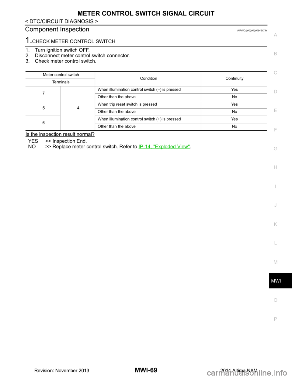
Component InspectionINFOID:0000000009461734
1.CHECK METER CONTROL SWITCH
1. Turn ignition switch OFF.
2. Disconnect meter control switch connector.
3. Check meter control switch.
Is the inspection result normal?
YES >> Inspection End.
NO >> Replace meter control switch. Refer to IP-14, "Exploded View"
.
Meter control switch
Condition Continuity
Te r m i n a l s
7
4When illumination control switch (
−) is pressed Yes
Other than the above No
5 When trip reset switch is pressed Yes
Other than the above No
6 When illumination control switch (+) is pressed Yes
Other than the above No
Revision: November 20132014 Altima NAMRevision: November 20132014 Altima NAM
Page 3325 of 4801

MWI-70
< DTC/CIRCUIT DIAGNOSIS >
STEERING SWITCH
STEERING SWITCH
DescriptionINFOID:0000000009461735
When one of the steering switches is pushed, the resistance in the steering switch changes the signal to
identify which button is controlling the information display.
Diagnosis ProcedureINFOID:0000000009461736
Regarding Wiring Diagram information, refer to MWI-32, "Wiring Diagram".
1.CHECK STEERING SWITCH CIRCUIT
1. Turn ignition switch OFF.
2. Disconnect combination meter harness connector M24 and spiral cable harness connector M30.
3. Check continuity between combination meter har ness connector M24 and spiral cable harness connector
M30.
4. Check continuity between combination meter harness connector M24 and ground.
Is the inspection results normal?
YES >> Inspection End.
NO >> Repair or replace harness or connectors.
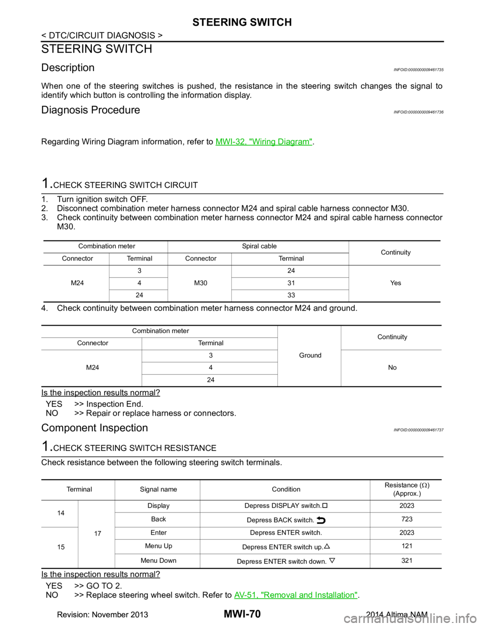
Component InspectionINFOID:0000000009461737
1.CHECK STEERING SWITCH RESISTANCE
Check resistance between the following steering switch terminals.
Is the inspection results normal?
YES >> GO TO 2.
NO >> Replace steering wheel switch. Refer to AV-51, "Removal and Installation"
.
Combination meter Spiral cable
Continuity
Connector Terminal Connector Terminal
M24 3
M30 24
Ye s
431
24 33
Combination meter GroundContinuity
Connector Terminal
M24 3
No
4
24
Terminal Signal name Condition Resistance (
Ω)
(Approx.)
14
17 Display Depress DISPLAY switch.
�†2023
Back Depress BACK switch. 723
15 Enter Depress ENTER switch. 2023
Menu Up Depress ENTER switch up. 121
Menu Down Depress ENTER switch down. 321
Revision: November 20132014 Altima NAMRevision: November 20132014 Altima NAM
Page 3330 of 4801

MWI
THE PARKING BRAKE RELEASE WARNING CONTINUES DISPLAYING, OR
DOES NOT DISPLAY
MWI-75
< SYMPTOM DIAGNOSIS >
C
D E
F
G H
I
J
K L
M B
A
O P
THE PARKING BRAKE RELEASE WA RNING CONTINUES DISPLAYING,
OR DOES NOT DISPLAY
DescriptionINFOID:0000000009461744
• The parking brake warning is displayed while driving the vehicle even though the parking brake is released.
• The parking brake warning is not displayed even though driving the vehicle with the parking brake
depressed.
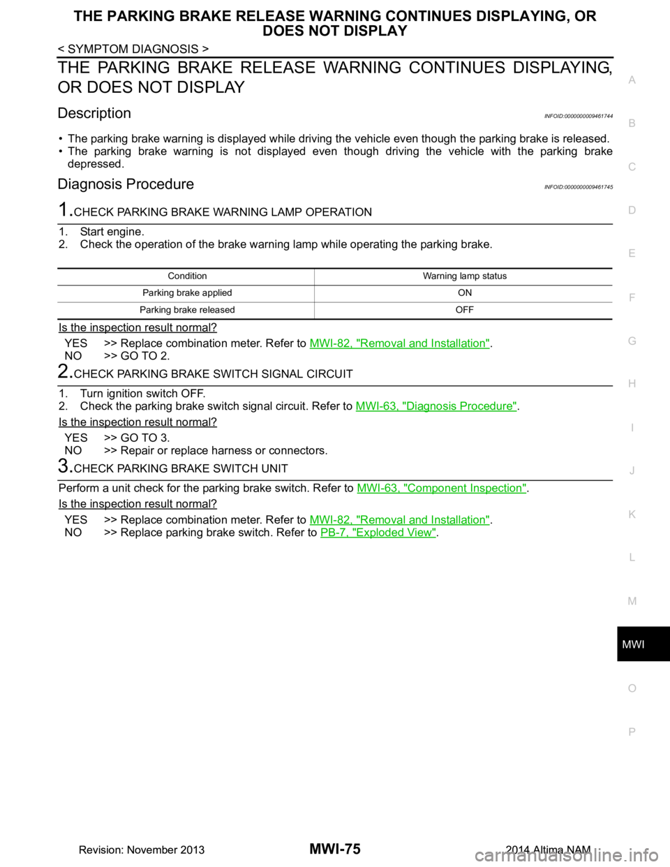
Diagnosis ProcedureINFOID:0000000009461745
1.CHECK PARKING BRAKE WARNING LAMP OPERATION
1. Start engine.
2. Check the operation of the brake warni ng lamp while operating the parking brake.
Is the inspection result normal?
YES >> Replace combination meter. Refer to MWI-82, "Removal and Installation".
NO >> GO TO 2.
2.CHECK PARKING BRAKE SWITCH SIGNAL CIRCUIT
1. Turn ignition switch OFF.
2. Check the parking brake switch signal circuit. Refer to MWI-63, "Diagnosis Procedure"
.
Is the inspection result normal?
YES >> GO TO 3.
NO >> Repair or replace harness or connectors.
3.CHECK PARKING BRAKE SWITCH UNIT
Perform a unit check for the parking brake switch. Refer to MWI-63, "Component Inspection"
.
Is the inspection result normal?
YES >> Replace combination meter. Refer to MWI-82, "Removal and Installation".
NO >> Replace parking brake switch. Refer to PB-7, "Exploded View"
.
Condition Warning lamp status
Parking brake applied ON
Parking brake released OFF
Revision: November 20132014 Altima NAMRevision: November 20132014 Altima NAM
Page 3340 of 4801

PB-2
< PRECAUTION >
PRECAUTIONS
PRECAUTION
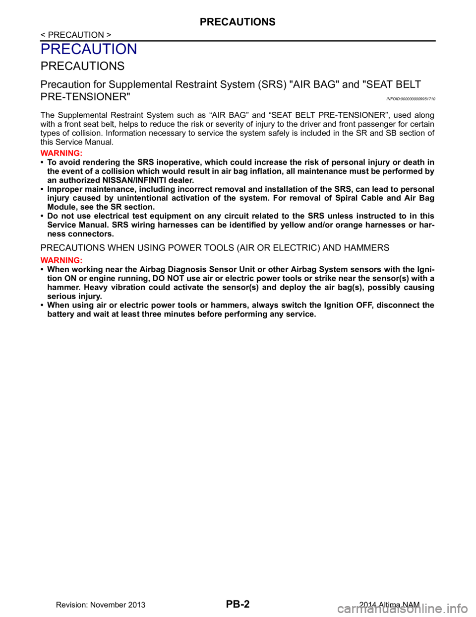
PRECAUTIONS
Precaution for Supplemental Restraint System (SRS) "AIR BAG" and "SEAT BELT
PRE-TENSIONER"
INFOID:0000000009951710
The Supplemental Restraint System such as “A IR BAG” and “SEAT BELT PRE-TENSIONER”, used along
with a front seat belt, helps to reduce the risk or severi ty of injury to the driver and front passenger for certain
types of collision. Information necessary to service the system safely is included in the SR and SB section of
this Service Manual.
WARNING:
• To avoid rendering the SRS inopera tive, which could increase the risk of personal injury or death in
the event of a collision which would result in air bag inflation, all maintenance must be performed by
an authorized NISS AN/INFINITI dealer.
• Improper maintenance, including in correct removal and installation of the SRS, can lead to personal
injury caused by unintent ional activation of the system. For re moval of Spiral Cable and Air Bag
Module, see the SR section.
• Do not use electrical test equipmen t on any circuit related to the SRS unless instructed to in this
Service Manual. SRS wiring harn esses can be identified by yellow and/or orange harnesses or har-
ness connectors.
PRECAUTIONS WHEN USING POWER TOOLS (AIR OR ELECTRIC) AND HAMMERS
WARNING:
• When working near the Airbag Diagnosis Sensor Unit or other Airbag System sensors with the Igni-
tion ON or engine running, DO NOT use air or electri c power tools or strike near the sensor(s) with a
hammer. Heavy vibration could activate the sensor( s) and deploy the air bag(s), possibly causing
serious injury.
• When using air or electric power tools or hammers , always switch the Ignition OFF, disconnect the
battery and wait at least three minutes before performing any service.
Revision: November 20132014 Altima NAM
Page 3350 of 4801

PCS
PCS-1
ELECTRICAL & POWER CONTROL
C
D E
F
G H
I
J
K L
B
SECTION PCS
A
O P
N
CONTENTS
POWER CONTROL SYSTEM
IPDM E/R
PRECAUTION ................ ...............................
3
PRECAUTIONS .............................................. .....3
Precaution for Supplemental Restraint System
(SRS) "AIR BAG" and "SEAT BELT PRE-TEN-
SIONER" ............................................................. ......
3
Precaution for Procedure without Cowl Top Cover ......3
SYSTEM DESCRIPTION ..............................4
COMPONENT PARTS ................................... .....4
Component Parts Location .................................. ......4
SYSTEM ..............................................................5
RELAY CONTROL SYSTEM ................................ ......5
RELAY CONTROL SYSTEM : System Diagram ......5
RELAY CONTROL SYSTEM : System Descrip-
tion ...................................................................... ......
6
POWER CONSUMPTION CONTROL SYSTEM ... ......6
POWER CONSUMPTION CONTROL SYSTEM :
System Diagram .................................................. ......
7
POWER CONSUMPTION CONTROL SYSTEM :
System Description ............................................. ......
7
DIAGNOSIS SYSTEM (IPDM E/R) ......................8
Diagnosis Description ......................................... ......8
CONSULT Function (IPDM E/R) ...............................9
ECU DIAGNOSIS INFORMATION ..............12
IPDM E/R (INTELLIGENT POWER DISTRI-
BUTION MODULE ENGINE ROOM) ............. ....
12
Reference Value ................................................. ....12
Fail Safe .................................................................19
DTC Index ..............................................................20
WIRING DIAGRAM ......................................21
IPDM E/R (INTELLIGENT POWER DISTRI-
BUTION MODULE ENGINE ROOM) ................
21
Wiring Diagram .................................................... ....21
DTC/CIRCUIT DIAGNOSIS .........................27
U1000 CAN COMM CIRCUIT ...........................27
Description ........................................................... ....27
DTC Logic ................................................................27
Diagnosis Procedure ...............................................27
U1010 CONTROL UNIT (CAN) .........................28
DTC Logic ................................................................28
Diagnosis Procedure ...............................................28
B2098 IGNITION RELAY ON STUCK ..............29
DTC Logic ................................................................29
Diagnosis Procedure ...............................................29
B2099 IGNITION RELAY OFF STUCK ............30
DTC Logic ................................................................30
Diagnosis Procedure ...............................................30
POWER SUPPLY AND GROUND CIRCUIT ....31
Diagnosis Procedure ...............................................31
REMOVAL AND INSTALLATION ...............32
IPDM E/R (INTELLIGENT POWER DISTRI-
BUTION MODULE ENGINE ROOM) ................
32
Removal and Installation ..................................... ....32
POWER DISTRIBUTION SYSTEM
PRECAUTION ...... ........................................
33
PRECAUTIONS .................................................33
Precaution for Supplemental Restraint System
(SRS) "AIR BAG" and "SEAT BELT PRE-TEN-
SIONER" ............................................................. ....
33
Precaution for Work .................................................33
PREPARATION ...........................................34
Revision: November 20132014 Altima NAMRevision: November 20132014 Altima NAM
Page 3351 of 4801

PCS-2
PREPARATION .............................................. ...34
Special Service Tool ............................................ ...34
SYSTEM DESCRIPTION ............................35
COMPONENT PARTS .................................... ...35
Component Parts Location .................................. ...35
SYSTEM .......................................................... ...36
POWER DISTRIBUTION SYST EM ........................ ...36
POWER DISTRIBUTION SYSTEM : System Dia-
gram .................................................................... ...
36
POWER DISTRIBUTION SYSTEM : System De-
scription ............................................................... ...
36
DIAGNOSIS SYSTEM (BCM) ............................38
COMMON ITEM ..................................................... ...38
COMMON ITEM : CONSULT Function (BCM -
COMMON ITEM) ................................................. ...
38
INTELLIGENT KEY ................................................ ...39
INTELLIGENT KEY : CONSULT Function (BCM -
INTELLIGENT KEY) ........ .......................................
39
ECU DIAGNOSIS INFORMATION ........... ...43
BCM, IPDM E/R .............................................. ...43
List of ECU Reference ......................................... ...43
WIRING DIAGRAM .....................................44
POWER DISTRIBUTION SYSTEM ................ ...44
Wiring Diagram .................................................... ...44
BASIC INSPECTION ...................................53
DIAGNOSIS AND REPAIR WORKFLOW ...... ...53
Work Flow ............................................................ ...53
DTC/CIRCUIT DIAGNOSIS ...................... ...56
U1000 CAN COMM CIRCUIT ......................... ...56
Description ........................................................... ...56
DTC Logic ...............................................................56
Diagnosis Procedure ..............................................56
U1010 CONTROL UNIT (CAN) .........................57
DTC Logic ............................................................ ...57
Diagnosis Procedure ..............................................57
B260A IGNITION RELAY ..................................58
DTC Logic ............................................................ ...58
Diagnosis Procedure ..............................................58
B2614 ACC RELAY CIRCUIT ...........................60
DTC Logic ............................................................ ...60
Diagnosis Procedure ..............................................60
Component Inspection (Relay) ...............................61
B2615 BLOWER RELAY CIRCUIT ...................62
DTC Logic ............................................................ ...62
Diagnosis Procedure ...............................................62
Component Inspection (Relay) ...............................63
B2616 IGNITION RELAY CIRCUIT ...................64
DTC Logic ............................................................ ...64
Diagnosis Procedure ...............................................64
Component Inspection (Relay) ...............................65
B2618 BCM .......................................................66
DTC Logic ............................................................ ...66
Diagnosis Procedure ...............................................66
B261A PUSH-BUTTON IGNITION SWITCH .....68
DTC Logic ............................................................ ...68
Diagnosis Procedure ...............................................68
B26F1 IGNITION RELAY ..................................70
DTC Logic ............................................................ ...70
Diagnosis Procedure ...............................................70
B26F2 IGNITION RELAY ..................................72
DTC Logic ............................................................ ...72
Diagnosis Procedure ...............................................72
B26F6 BCM .......................................................74
DTC Logic ............................................................ ...74
Diagnosis Procedure ...............................................74
PUSH-BUTTON IGNITION SWITCH .................76
Component Function Check ............................... ...76
Diagnosis Procedure ...............................................76
Component Inspection ............................................77
POWER SUPPLY AND GROUND CIRCUIT .....79
BCM ........................................................................ ...79
BCM : Diagnosis Procedure ....................................79
IPDM E/R (INTELLIGENT POWER DISTRIBU-
TION MODULE ENGINE ROOM) ........................... ...
79
IPDM E/R (INTELLIGENT POWER DISTRIBU-
TION MODULE ENGINE ROOM) : Diagnosis Pro-
cedure .................................................................. ...
79
SYMPTOM DIAGNOSIS ............................81
PUSH-BUTTON IGNITION SWITCH DOES
NOT OPERATE .............................................. ...
81
Description ........................................................... ...81
Diagnosis Procedure ...............................................81
REMOVAL AND INSTALLATION ..............82
BCM (BODY CONTROL MODULE) ............... ...82
Removal and Installation .........................................82
PUSH BUTTON IGNITION SWITCH .............. ...83
Exploded View ..................................................... ...83
Removal and Installation .........................................83
Revision: November 20132014 Altima NAMRevision: November 20132014 Altima NAM
Page 3352 of 4801
![NISSAN TEANA 2014 Service Manual
PCS
PRECAUTIONSPCS-3
< PRECAUTION > [IPDM E/R]
C
D E
F
G H
I
J
K L
B
A
O P
N
PRECAUTION
PRECAUTIONS
Precaution for Supplemental
Restraint System (SRS) "AIR BAG" and "SEAT BELT
PRE-TENSIONER"
INFO NISSAN TEANA 2014 Service Manual
PCS
PRECAUTIONSPCS-3
< PRECAUTION > [IPDM E/R]
C
D E
F
G H
I
J
K L
B
A
O P
N
PRECAUTION
PRECAUTIONS
Precaution for Supplemental
Restraint System (SRS) "AIR BAG" and "SEAT BELT
PRE-TENSIONER"
INFO](/manual-img/5/57390/w960_57390-3351.png)
PCS
PRECAUTIONSPCS-3
< PRECAUTION > [IPDM E/R]
C
D E
F
G H
I
J
K L
B
A
O P
N
PRECAUTION
PRECAUTIONS
Precaution for Supplemental
Restraint System (SRS) "AIR BAG" and "SEAT BELT
PRE-TENSIONER"
INFOID:0000000009951596
The Supplemental Restraint System such as “A IR BAG” and “SEAT BELT PRE-TENSIONER”, used along
with a front seat belt, helps to reduce the risk or severi ty of injury to the driver and front passenger for certain
types of collision. Information necessary to service t he system safely is included in the SR and SB section of
this Service Manual.
WARNING:
• To avoid rendering the SRS inoper ative, which could increase the risk of personal injury or death in
the event of a collision which would result in air bag inflation, all maintenance must be performed by
an authorized NISSAN/INFINITI dealer.
• Improper maintenance, including in correct removal and installation of the SRS, can lead to personal
injury caused by unintentional act ivation of the system. For removal of Spiral Cable and Air Bag
Module, see the SR section.
• Do not use electrical test equipm ent on any circuit related to the SRS unless instructed to in this
Service Manual. SRS wiring harnesses can be identi fied by yellow and/or orange harnesses or har-
ness connectors.
PRECAUTIONS WHEN USING POWER TOOLS (AIR OR ELECTRIC) AND HAMMERS
WARNING:
• When working near the Airbag Diagnosis Sensor Un it or other Airbag System sensors with the Igni-
tion ON or engine running, DO NOT use air or el ectric power tools or strike near the sensor(s) with a
hammer. Heavy vibration could activate the sensor( s) and deploy the air bag(s), possibly causing
serious injury.
• When using air or electric power tools or hammers , always switch the Ignition OFF, disconnect the
battery and wait at least three mi nutes before performing any service.
Precaution for Procedure without Cowl Top CoverINFOID:0000000009461595
When performing the procedure after removing cowl top cover, cover
the lower end of windshield with urethane, etc.
PIIB3706J
Revision: November 20132014 Altima NAMRevision: November 20132014 Altima NAM