2014 NISSAN TEANA ignition
[x] Cancel search: ignitionPage 3169 of 4801
![NISSAN TEANA 2014 Service Manual
PRECAUTIONSLU-19
< PRECAUTION > [VQ35DE]
C
D E
F
G H
I
J
K L
M A
LU
NP
O
PRECAUTION
PRECAUTIONS
Precaution for Supplemental
Restraint System (SRS) "AIR BAG" and "SEAT BELT
PRE-TENSIONER"
INFOID:00 NISSAN TEANA 2014 Service Manual
PRECAUTIONSLU-19
< PRECAUTION > [VQ35DE]
C
D E
F
G H
I
J
K L
M A
LU
NP
O
PRECAUTION
PRECAUTIONS
Precaution for Supplemental
Restraint System (SRS) "AIR BAG" and "SEAT BELT
PRE-TENSIONER"
INFOID:00](/manual-img/5/57390/w960_57390-3168.png)
PRECAUTIONSLU-19
< PRECAUTION > [VQ35DE]
C
D E
F
G H
I
J
K L
M A
LU
NP
O
PRECAUTION
PRECAUTIONS
Precaution for Supplemental
Restraint System (SRS) "AIR BAG" and "SEAT BELT
PRE-TENSIONER"
INFOID:0000000009951686
The Supplemental Restraint System such as “A IR BAG” and “SEAT BELT PRE-TENSIONER”, used along
with a front seat belt, helps to reduce the risk or severi ty of injury to the driver and front passenger for certain
types of collision. Information necessary to service t he system safely is included in the SR and SB section of
this Service Manual.
WARNING:
• To avoid rendering the SRS inoper ative, which could increase the risk of personal injury or death in
the event of a collision which would result in air bag inflation, all maintenance must be performed by
an authorized NISSAN/INFINITI dealer.
• Improper maintenance, including in correct removal and installation of the SRS, can lead to personal
injury caused by unintentional act ivation of the system. For removal of Spiral Cable and Air Bag
Module, see the SR section.
• Do not use electrical test equipm ent on any circuit related to the SRS unless instructed to in this
Service Manual. SRS wiring harnesses can be identi fied by yellow and/or orange harnesses or har-
ness connectors.
PRECAUTIONS WHEN USING POWER TOOLS (AIR OR ELECTRIC) AND HAMMERS
WARNING:
• When working near the Airbag Diagnosis Sensor Un it or other Airbag System sensors with the Igni-
tion ON or engine running, DO NOT use air or el ectric power tools or strike near the sensor(s) with a
hammer. Heavy vibration could activate the sensor( s) and deploy the air bag(s), possibly causing
serious injury.
• When using air or electric power tools or hammers , always switch the Ignition OFF, disconnect the
battery and wait at least three mi nutes before performing any service.
Precaution for Liquid GasketINFOID:0000000009461043
REMOVAL OF LIQUID GASKET
• After removing the bolts and nuts, separate the mating surface and
remove the liquid gasket using Tool (A).
CAUTION:
Be careful not to damage the mating surfaces.
• In areas where the cutter is difficult to use, use a plastic hammer to lightly tap (1) the cutter where the liquid gasket is applied. Use a
plastic hammer to slide (2) the cutter by tapping on the side.
CAUTION:
Do not damage the mating surfaces.
LIQUID GASKET APPLICATION PROCEDURE
1. Using a scraper, remove the old liquid gasket adhering to the gasket application surface and the mating surface.
• Remove the liquid gasket completely from the groove of the
gasket application surface, mounting bolts, and bolt holes.
2. Thoroughly clean the gasket application surface and the mating surface and remove adhering moisture, grease and foreign
materials.
3. Attach the liquid gasket tube to the tube presser. Use Genuine Silicone RTV Seal ant or equivalent. Refer to
GI-21, "Recommended Chemical Products and Sealants"
.
Tool Number (A): KV10111100 (J-37228)
AWBIA1249GB
PBIC0003E
Revision: November 20132014 Altima NAM
Page 3187 of 4801

PRECAUTIONSMA-3
< PRECAUTION >
C
D E
F
G H
I
J
K L
M B
MA
N
O A
PRECAUTION
PRECAUTIONS
Precaution for Supplemental
Restraint System (SRS) "AIR BAG" and "SEAT BELT
PRE-TENSIONER"
INFOID:0000000009951663
The Supplemental Restraint System such as “A IR BAG” and “SEAT BELT PRE-TENSIONER”, used along
with a front seat belt, helps to reduce the risk or severi ty of injury to the driver and front passenger for certain
types of collision. Information necessary to service t he system safely is included in the SR and SB section of
this Service Manual.
WARNING:
• To avoid rendering the SRS inoper ative, which could increase the risk of personal injury or death in
the event of a collision which would result in air bag inflation, all maintenance must be performed by
an authorized NISSAN/INFINITI dealer.
• Improper maintenance, including in correct removal and installation of the SRS, can lead to personal
injury caused by unintentional act ivation of the system. For removal of Spiral Cable and Air Bag
Module, see the SR section.
• Do not use electrical test equipm ent on any circuit related to the SRS unless instructed to in this
Service Manual. SRS wiring harnesses can be identi fied by yellow and/or orange harnesses or har-
ness connectors.
PRECAUTIONS WHEN USING POWER TOOLS (AIR OR ELECTRIC) AND HAMMERS
WARNING:
• When working near the Airbag Diagnosis Sensor Un it or other Airbag System sensors with the Igni-
tion ON or engine running, DO NOT use air or el ectric power tools or strike near the sensor(s) with a
hammer. Heavy vibration could activate the sensor( s) and deploy the air bag(s), possibly causing
serious injury.
• When using air or electric power tools or hammers , always switch the Ignition OFF, disconnect the
battery and wait at least three mi nutes before performing any service.
Revision: November 20132014 Altima NAM
Page 3199 of 4801
ENGINE MAINTENANCE (QR25DE)MA-15
< PERIODIC MAINTENANCE >
C
D E
F
G H
I
J
K L
M B
MA
N
O A
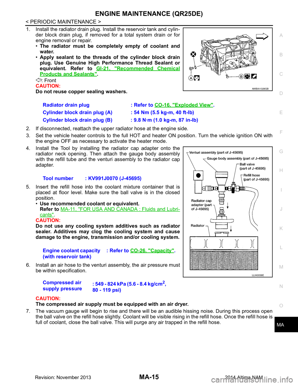
1. Install the radiator drain plug. Install the reservoir tank and cylin-
der block drain plug, if removed for a total system drain or for
engine removal or repair.
• The radiator must be completely empty of coolant and
water.
• Apply sealant to the threads of the cylinder block drain
plug. Use Genuine High Pe rformance Thread Sealant or
equivalent. Refer to GI-21, "Recommended Chemical
Products and Sealants".
: Front
CAUTION:
Do not reuse copper sealing washers.
2. If disconnected, reattach the upper radiator hose at the engine side.
3. Set the vehicle heater controls to the full HOT and heat er ON position. Turn the vehicle ignition ON with
the engine OFF as necessary to activate the heater mode.
4. Install the Tool by installing the radiator cap adapter onto the radiator neck opening. Then attach the gauge body assembly
with the refill tube and the venturi assembly to the radiator cap
adapter.
5. Insert the refill hose into the coolant mixture container that is
placed at floor level. Make sure the ball valve is in the closed
position.
• Use recommended coolant or equivalent.
Refer to MA-11, "FOR USA AND CANADA : Fluids and Lubri-
cants".
CAUTION:
Do not use any cooling system additives such as radiator
sealer. Additives may clog th e cooling system and cause
damage to the engine, transmission and/or cooling system.
6. Install an air hose to the venturi assembly, the air pressure must be within specification.
CAUTION:
The compressed air supply must be equipped with an air dryer.
7. The vacuum gauge will begin to rise and there will be an audible hissing noise. During this process open the ball valve on the refill hose slightly. Coolant will be vi sible rising in the refill hose. Once the refill hose is
full of coolant, close the ball valve. Th is will purge any air trapped in the refill hose.
Radiator drain plug : Refer to
CO-16, "Exploded View"
.
Cylinder block drain plug (A) : 54 Nm (5.5 kg-m, 40 ft-lb)
Cylinder block drain plug (B) : 9.8 N·m (1.0 kg-m, 87 in-lb)
Tool number : KV991J0070 (J-45695)
Engine coolant capacity
(with reservoir tank) : Refer to
CO-26, "Capacity"
.
Compressed air
supply pressure : 549 - 824 kPa (5.6 - 8.4 kg/cm
2,
80 - 119 psi)
AWBIA1328GB
LLIA0058E
Revision: November 20132014 Altima NAM
Page 3204 of 4801
MA-20
< PERIODIC MAINTENANCE >
ENGINE MAINTENANCE (QR25DE)
SPARK PLUG : Removal and Installation
INFOID:0000000009464551
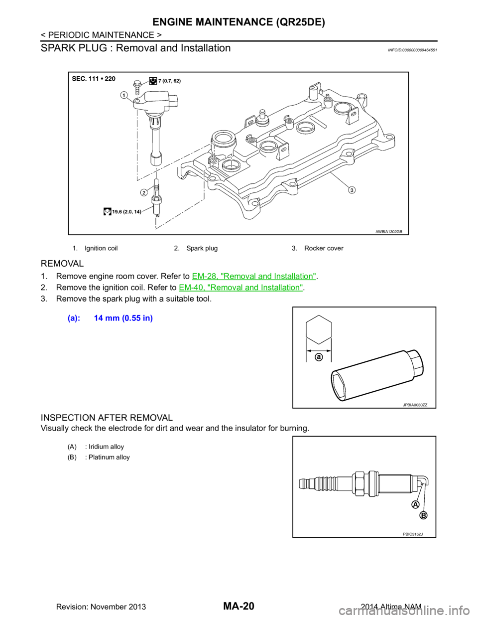
REMOVAL
1. Remove engine room cover. Refer to EM-28, "Removal and Installation".
2. Remove the ignition coil. Refer to EM-40, "Removal and Installation"
.
3. Remove the spark plug with a suitable tool.
INSPECTION AFTER REMOVAL
Visually check the electrode for dirt and wear and the insulator for burning.
1. Ignition coil 2. Spark plug 3. Rocker cover
AWBIA1302GB
(a): 14 mm (0.55 in)
JPBIA0030ZZ
(A) : Iridium alloy
(B) : Platinum alloy
PBIC3152J
Revision: November 20132014 Altima NAM
Page 3208 of 4801
MA-24
< PERIODIC MAINTENANCE >
ENGINE MAINTENANCE (VQ35DE)
REFILLING ENGINE COOLANT
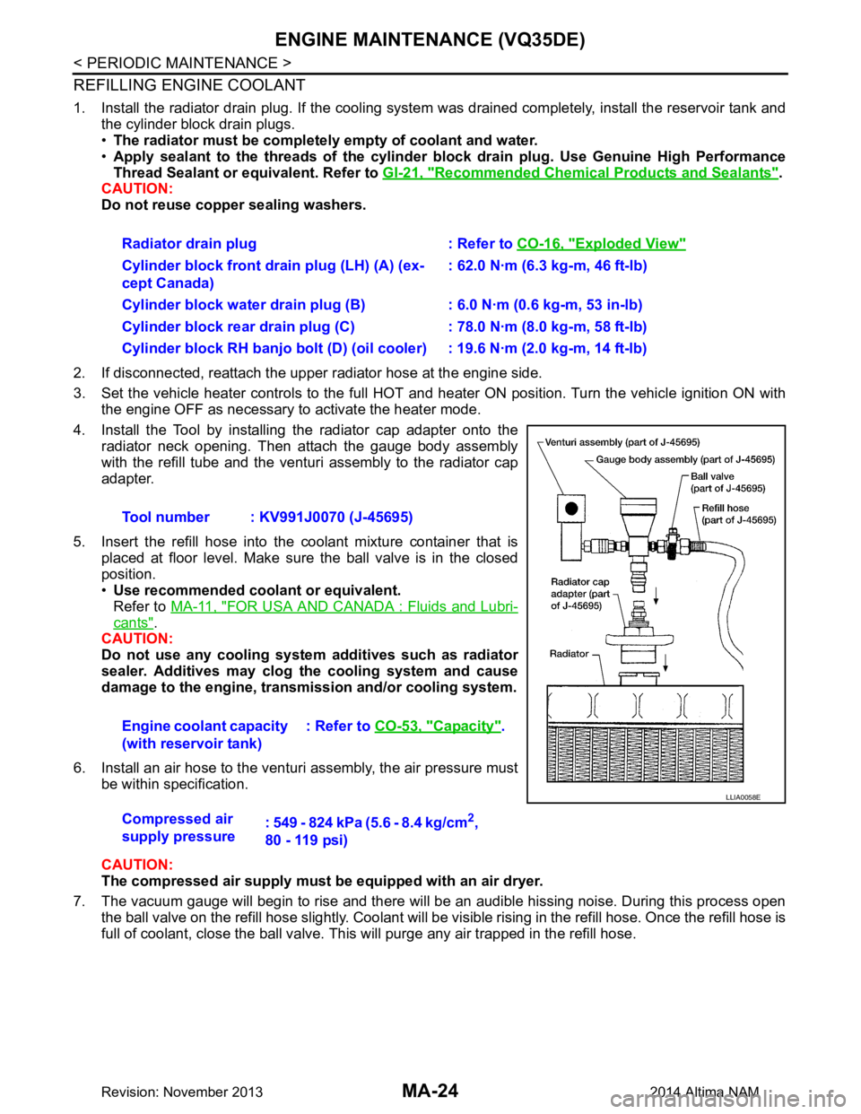
1. Install the radiator drain plug. If the cooling system was drained completely, install the reservoir tank and
the cylinder block drain plugs.
• The radiator must be complete ly empty of coolant and water.
• Apply sealant to the threads of the cylinder block drain plug. Use Genuine High Performance
Thread Sealant or equivalent. Refer to GI-21, "Recommended Chemical Products and Sealants"
.
CAUTION:
Do not reuse copp er sealing washers.
2. If disconnected, reattach the upper radiator hose at the engine side.
3. Set the vehicle heater controls to the full HOT and heat er ON position. Turn the vehicle ignition ON with
the engine OFF as necessary to activate the heater mode.
4. Install the Tool by installing the radiator cap adapter onto the radiator neck opening. Then attach the gauge body assembly
with the refill tube and the venturi assembly to the radiator cap
adapter.
5. Insert the refill hose into the coolant mixture container that is placed at floor level. Make sure the ball valve is in the closed
position.
• Use recommended coolant or equivalent.
Refer to MA-11, "FOR USA AND CANADA : Fluids and Lubri-
cants".
CAUTION:
Do not use any cooling system additives such as radiator
sealer. Additives may clog th e cooling system and cause
damage to the engine, transm ission and/or cooling system.
6. Install an air hose to the venturi assembly, the air pressure must be within specification.
CAUTION:
The compressed air supply must be equipped with an air dryer.
7. The vacuum gauge will begin to rise and there will be an audible hissing noise. During this process open the ball valve on the refill hose slightly. Coolant will be vi sible rising in the refill hose. Once the refill hose is
full of coolant, close the ball valve. This will purge any air trapped in the refill hose. Radiator drain plug : Refer to
CO-16, "Exploded View"
Cylinder block front drain plug (LH) (A) (ex-
cept Canada) : 62.0 N·m (6.3 kg-m, 46 ft-lb)
Cylinder block water drain plug (B) : 6.0 N·m (0.6 kg-m, 53 in-lb)
Cylinder block rear drain plug (C) : 78.0 N·m (8.0 kg-m, 58 ft-lb)
Cylinder block RH banjo bolt (D) (oil cooler) : 19.6 N·m (2.0 kg-m, 14 ft-lb)
Tool number : KV991J0070 (J-45695)
Engine coolant capacity
(with reservoir tank) : Refer to
CO-53, "Capacity"
.
Compressed air
supply pressure : 549 - 824 kPa (5.6 - 8.4 kg/cm
2,
80 - 119 psi)
LLIA0058E
Revision: November 20132014 Altima NAM
Page 3213 of 4801
ENGINE MAINTENANCE (VQ35DE)MA-29
< PERIODIC MAINTENANCE >
C
D E
F
G H
I
J
K L
M B
MA
N
O A
SPARK PLUG : Removal and InstallationINFOID:0000000009464562
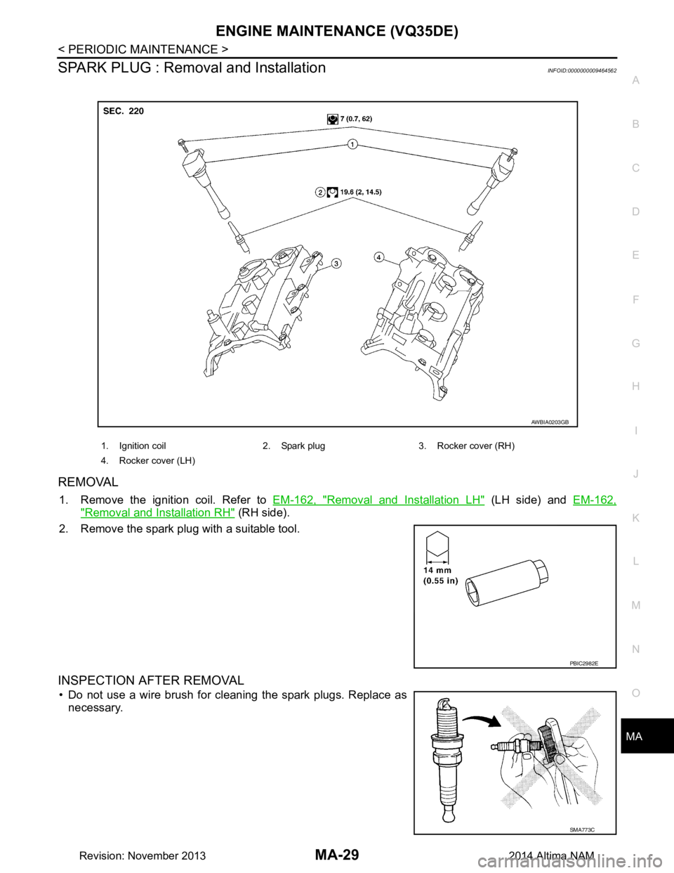
REMOVAL
1. Remove the ignition coil. Refer to
EM-162, "Removal and Installation LH" (LH side) and EM-162,
"Removal and Installation RH" (RH side).
2. Remove the spark plug with a suitable tool.
INSPECTION AFTER REMOVAL
• Do not use a wire brush for cleaning the spark plugs. Replace as necessary.
1. Ignition coil 2. Spark plug 3. Rocker cover (RH)
4. Rocker cover (LH)
AWBIA0203GB
PBIC2982E
SMA773C
Revision: November 20132014 Altima NAM
Page 3225 of 4801
CHASSIS AND BODY MAINTENANCEMA-41
< PERIODIC MAINTENANCE >
C
D E
F
G H
I
J
K L
M B
MA
N
O A
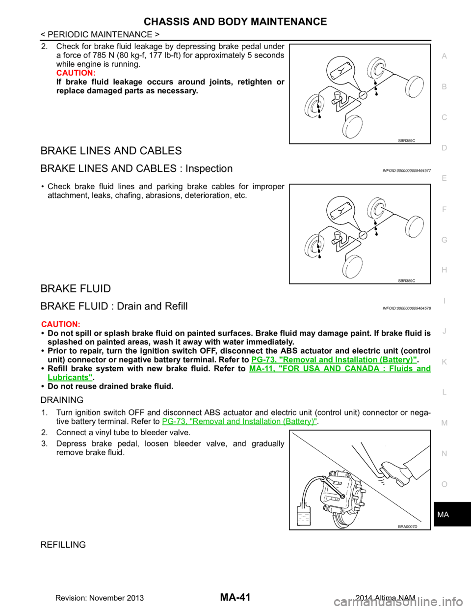
2. Check for brake fluid leakage by depressing brake pedal under
a force of 785 N (80 kg-f, 177 lb-ft) for approximately 5 seconds
while engine is running.
CAUTION:
If brake fluid leakage occurs around joints, retighten or
replace damaged parts as necessary.
BRAKE LINES AND CABLES
BRAKE LINES AND CABLES : InspectionINFOID:0000000009464577
• Check brake fluid lines and parking brake cables for improper attachment, leaks, chafing, abrasions, deterioration, etc.
BRAKE FLUID
BRAKE FLUID : Drain and RefillINFOID:0000000009464578
CAUTION:
• Do not spill or splash brake fluid on painted surf aces. Brake fluid may damage paint. If brake fluid is
splashed on painted areas, wash it away with water immediately.
• Prior to repair, turn the ignition switch OFF, disconnect the ABS actuator and electric unit (control
unit) connector or negative battery terminal. Refer to PG-73, "Removal and Installation (Battery)"
.
• Refill brake system with new brake fluid. Refer to MA-11, "FOR USA AND CANADA : Fluids and
Lubricants".
• Do not reuse drained brake fluid.
DRAINING
1. Turn ignition switch OFF and disconnect ABS actuat or and electric unit (control unit) connector or nega-
tive battery terminal. Refer to PG-73, "Removal and Installation (Battery)"
.
2. Connect a vinyl tube to bleeder valve.
3. Depress brake pedal, loosen bleeder valve, and gradually remove brake fluid.
REFILLING
SBR389C
SBR389C
BRA0007D
Revision: November 20132014 Altima NAM
Page 3232 of 4801
MIR-2
< PRECAUTION >
PRECAUTIONS
PRECAUTION
PRECAUTIONS
Precaution for Supplemental Restraint System (SRS) "AIR BAG" and "SEAT BELT
PRE-TENSIONER"
INFOID:0000000009951574
The Supplemental Restraint System such as “A IR BAG” and “SEAT BELT PRE-TENSIONER”, used along
with a front seat belt, helps to reduce the risk or severi ty of injury to the driver and front passenger for certain
types of collision. Information necessary to service the system safely is included in the SR and SB section of
this Service Manual.
WARNING:
• To avoid rendering the SRS inopera tive, which could increase the risk of personal injury or death in
the event of a collision which would result in air bag inflation, all maintenance must be performed by
an authorized NISS AN/INFINITI dealer.
• Improper maintenance, including in correct removal and installation of the SRS, can lead to personal
injury caused by unintent ional activation of the system. For re moval of Spiral Cable and Air Bag
Module, see the SR section.
• Do not use electrical test equipmen t on any circuit related to the SRS unless instructed to in this
Service Manual. SRS wiring harn esses can be identified by yellow and/or orange harnesses or har-
ness connectors.
PRECAUTIONS WHEN USING POWER TOOLS (AIR OR ELECTRIC) AND HAMMERS
WARNING:
• When working near the Airbag Diagnosis Sensor Unit or other Airbag System sensors with the Igni-
tion ON or engine running, DO NOT use air or electri c power tools or strike near the sensor(s) with a
hammer. Heavy vibration could activate the sensor( s) and deploy the air bag(s), possibly causing
serious injury.
• When using air or electric power tools or hammers , always switch the Ignition OFF, disconnect the
battery and wait at least three minutes before performing any service.
Precaution for WorkINFOID:0000000009463520
• When removing or disassembling each component, be careful not to damage or deform it. If a component may be subject to interference, be sure to protect it with a shop cloth.
• When removing (disengaging) components with a screwdriver or similar tool, be sure to wrap the component with a shop cloth or vinyl tape to protect it.
• Protect the removed parts with a s hop cloth and prevent them from being dropped.
• Replace a deformed or damaged clip.
• If a part is specified as a non-reusable part, always replace it with a new one.
• Be sure to tighten bolts and nuts securely to the specified torque.
• After installation is complete, be sure to check that each part works properly.
• Follow the steps below to clean components:
- Water soluble dirt:
• Dip a soft cloth into lukewarm water, wring the water out of the cloth and wipe the dirty area.
• Then rub with a soft, dry cloth.
- Oily dirt:
• Dip a soft cloth into lukewarm water with mild detergent (concentration: within 2 to 3%) and wipe the dirty area.
• Then dip a cloth into fresh water, wring the water out of the cloth and wipe the detergent off.
• Then rub with a soft, dry cloth.
- Do not use organic solvent such as thinner, benzene, alcohol or gasoline.
- For genuine leather seats, use a genuine leather seat cleaner.
Revision: November 20132014 Altima NAMRevision: November 20132014 Altima NAM