2014 NISSAN TEANA ignition
[x] Cancel search: ignitionPage 2482 of 4801
FL-2
< PRECAUTION >
PRECAUTIONS
PRECAUTION
PRECAUTIONS
Precaution for Supplemental Restraint System (SRS) "AIR BAG" and "SEAT BELT
PRE-TENSIONER"
INFOID:0000000009951691
The Supplemental Restraint System such as “A IR BAG” and “SEAT BELT PRE-TENSIONER”, used along
with a front seat belt, helps to reduce the risk or severi ty of injury to the driver and front passenger for certain
types of collision. Information necessary to service the system safely is included in the SR and SB section of
this Service Manual.
WARNING:
• To avoid rendering the SRS inopera tive, which could increase the risk of personal injury or death in
the event of a collision which would result in air bag inflation, all maintenance must be performed by
an authorized NISS AN/INFINITI dealer.
• Improper maintenance, including in correct removal and installation of the SRS, can lead to personal
injury caused by unintent ional activation of the system. For re moval of Spiral Cable and Air Bag
Module, see the SR section.
• Do not use electrical test equipmen t on any circuit related to the SRS unless instructed to in this
Service Manual. SRS wiring harn esses can be identified by yellow and/or orange harnesses or har-
ness connectors.
PRECAUTIONS WHEN USING POWER TOOLS (AIR OR ELECTRIC) AND HAMMERS
WARNING:
• When working near the Airbag Diagnosis Sensor Unit or other Airbag System sensors with the Igni-
tion ON or engine running, DO NOT use air or electri c power tools or strike near the sensor(s) with a
hammer. Heavy vibration could activate the sensor( s) and deploy the air bag(s), possibly causing
serious injury.
• When using air or electric power tools or hammers , always switch the Ignition OFF, disconnect the
battery and wait at least three minutes before performing any service.
General PrecautionINFOID:0000000009460597
WARNING:
When replacing fuel line parts, be sure to observe the following.
• Put a “CAUTION: FLAMMABLE” sign in the work area.
• Be sure to work in a well ventilated area and have a CO
2 fire extinguisher.
• Do not smoke while working on the fuel system. Keep open flames and sparks away from the work
area.
CAUTION:
• Before removing fuel line parts, carry out the following procedures:
- Put drained fuel in an explosi on-proof container and put the lid on securely. Keep the container in
safe area.
- Release fuel pressure from the fuel lines. Refer to EC-182, "Work Procedure"
(QR25DE), EC-687,
"Work Procedure" (VQ35DE).
- Disconnect the battery ground cable.
• Always replace O-rings and clamps with new ones.
• Do not kink or twist tubes when they are being installed.
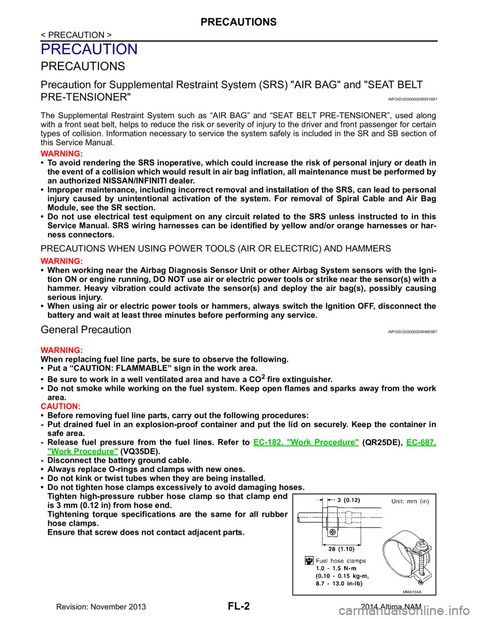
• Do not tighten hose clamps excessi vely to avoid damaging hoses.
Tighten high-pressure rubber hose clamp so that clamp end
is 3 mm (0.12 in) from hose end.
Tightening torque specificati ons are the same for all rubber
hose clamps.
Ensure that screw does not contact adjacent parts.
MMA104A
Revision: November 20132014 Altima NAM
Page 2489 of 4801
FUEL LEVEL SENSOR UNIT, FUEL FILTER AND FUEL PUMP ASSEMBLYFL-9
< REMOVAL AND INSTALLATION >
C
D E
F
G H
I
J
K L
M A
FL
NP
O
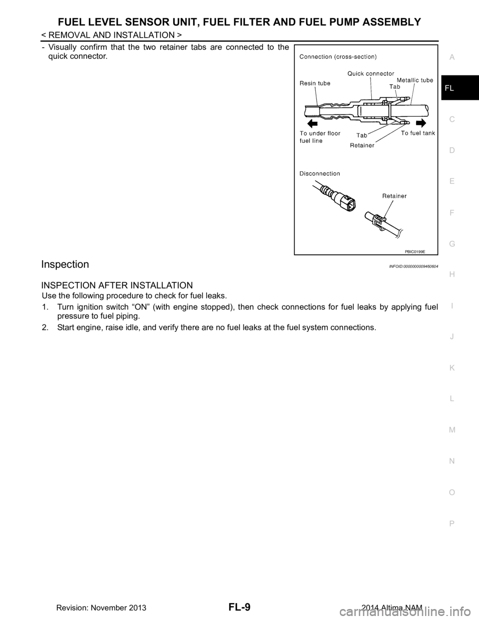
- Visually confirm that the two retainer tabs are connected to the
quick connector.
InspectionINFOID:0000000009460604
INSPECTION AFTER INSTALLATION
Use the following procedure to check for fuel leaks.
1. Turn ignition switch “ON” (with engine stopped), t hen check connections for fuel leaks by applying fuel
pressure to fuel piping.
2. Start engine, raise idle, and verify there are no fuel leaks at the fuel system connections.
PBIC0199E
Revision: November 20132014 Altima NAM
Page 2493 of 4801
FUEL TANKFL-13
< REMOVAL AND INSTALLATION >
C
D E
F
G H
I
J
K L
M A
FL
NP
O
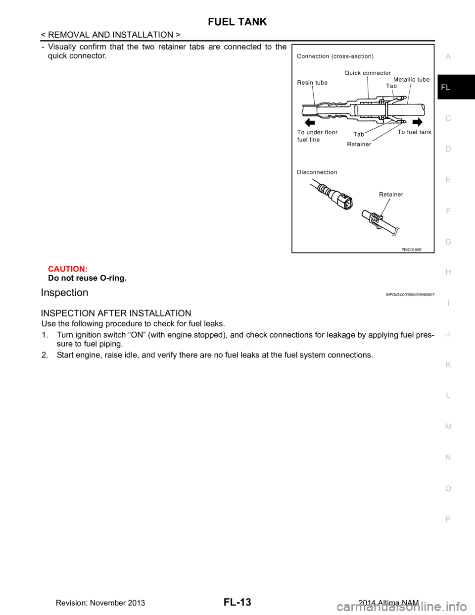
- Visually confirm that the two retainer tabs are connected to the
quick connector.
CAUTION:
Do not reuse O-ring.
InspectionINFOID:0000000009460607
INSPECTION AFTER INSTALLATION
Use the following procedure to check for fuel leaks.
1. Turn ignition switch “ON” (with engine stopped), and check connections for leakage by applying fuel pres-
sure to fuel piping.
2. Start engine, raise idle, and verify there are no fuel leaks at the fuel system connections.
PBIC0199E
Revision: November 20132014 Altima NAM
Page 2503 of 4801
FSU-2
< PRECAUTION >
PRECAUTIONS
PRECAUTION
PRECAUTIONS
Precaution for Supplemental Restraint System (SRS) "AIR BAG" and "SEAT BELT
PRE-TENSIONER"
INFOID:0000000009951705
The Supplemental Restraint System such as “A IR BAG” and “SEAT BELT PRE-TENSIONER”, used along
with a front seat belt, helps to reduce the risk or severi ty of injury to the driver and front passenger for certain
types of collision. Information necessary to service the system safely is included in the SR and SB section of
this Service Manual.
WARNING:
• To avoid rendering the SRS inopera tive, which could increase the risk of personal injury or death in
the event of a collision which would result in air bag inflation, all maintenance must be performed by
an authorized NISS AN/INFINITI dealer.
• Improper maintenance, including in correct removal and installation of the SRS, can lead to personal
injury caused by unintent ional activation of the system. For re moval of Spiral Cable and Air Bag
Module, see the SR section.
• Do not use electrical test equipmen t on any circuit related to the SRS unless instructed to in this
Service Manual. SRS wiring harn esses can be identified by yellow and/or orange harnesses or har-
ness connectors.
PRECAUTIONS WHEN USING POWER TOOLS (AIR OR ELECTRIC) AND HAMMERS
WARNING:
• When working near the Airbag Diagnosis Sensor Unit or other Airbag System sensors with the Igni-
tion ON or engine running, DO NOT use air or electri c power tools or strike near the sensor(s) with a
hammer. Heavy vibration could activate the sensor( s) and deploy the air bag(s), possibly causing
serious injury.
• When using air or electric power tools or hammers , always switch the Ignition OFF, disconnect the
battery and wait at least three minutes before performing any service.
General PrecautionsINFOID:0000000009460620
• When installing rubber bushings, the final tightening mu st be carried out under unladen conditions with tires
on ground. Oil might shorten the life of rubber bushings. Be sure to wipe off any spilled oil.
- Unladen conditions mean that fuel, engine coolant and lubricant are full. Spare tire, jack, hand tools and mats are in designated positions.
• After servicing suspension parts, be sure to check wheel alignment.
• Self-lock nuts are not reusable. Always use new ones when installing. Since new self-lock nuts are pre-oiled,
tighten as they are.
Precaution for Procedure without Cowl Top CoverINFOID:0000000009460621
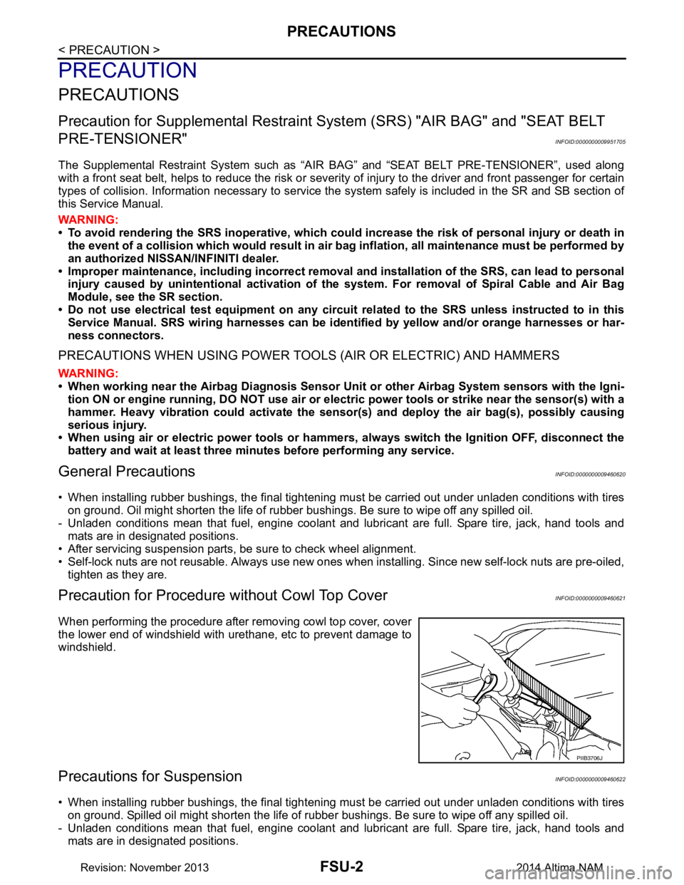
When performing the procedure after removing cowl top cover, cover
the lower end of windshield with urethane, etc to prevent damage to
windshield.
Precautions for SuspensionINFOID:0000000009460622
• When installing rubber bushings, the final tightening mu st be carried out under unladen conditions with tires
on ground. Spilled oil might shorten the life of rubber bushings. Be sure to wipe off any spilled oil.
- Unladen conditions mean that fuel, engine coolant and lubricant are full. Spare tire, jack, hand tools and mats are in designated positions.
PIIB3706J
Revision: November 20132014 Altima NAM
Page 2534 of 4801
GI-6
< HOW TO USE THIS MANUAL >
HOW TO FOLLOW TROUBLE DIAGNOSES
HOW TO FOLLOW TROUBLE DIAGNOSES
DescriptionINFOID:0000000009462973
NOTICE:
Trouble diagnoses indicate work procedures required to diagnose problems effectively. Observe the following
instructions before diagnosing.
• Before performing trouble diagnoses, read the “Work Flow” in each section.
• After repairs, re-check that the problem has been completely eliminated.
• Refer to Component Parts and Harness Connector Locat ion for the Systems described in each section for
identification/location of components and harness connectors.
• When checking circuit continuity, ignition switch should be OFF.
• Refer to the Circuit Diagram for quick pinpoint check.
If you need to check circuit continui ty between harness connectors in more detail, such as when a sub-har-
ness is used, refer to Wiring Diagram in each individual section and Harness Layout in PG section for identi-
fication of harness connectors.
• Before checking voltage at connectors, check battery voltage.
• After accomplishing the Diagnosis Procedures and Elec trical Components Inspection, make sure that all
harness connectors are reconnected as they were.
How to Follow Test Grou ps in Trouble DiagnosisINFOID:0000000009462974
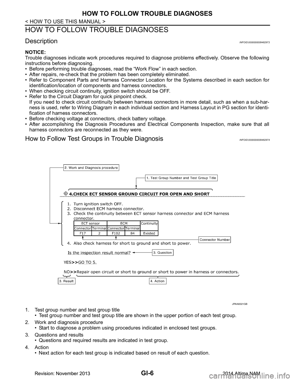
1. Test group number and test group title
• Test group number and test group title are s hown in the upper portion of each test group.
2. Work and diagnosis procedure • Start to diagnose a problem using procedur es indicated in enclosed test groups.
3. Questions and results • Questions and required results are indicated in test group.
4. Action • Next action for each test group is indicated based on result of each question.
JPAIA0021GB
Revision: November 20132014 Altima NAMRevision: November 20132014 Altima NAM
Page 2540 of 4801
GI-12
< HOW TO USE THIS MANUAL >
HOW TO READ WIRING DIAGRAMS
• ignition switch is “OFF”,
• doors, hood and trunk lid/back door are closed,
• pedals are not depressed, and
• parking brake is released.
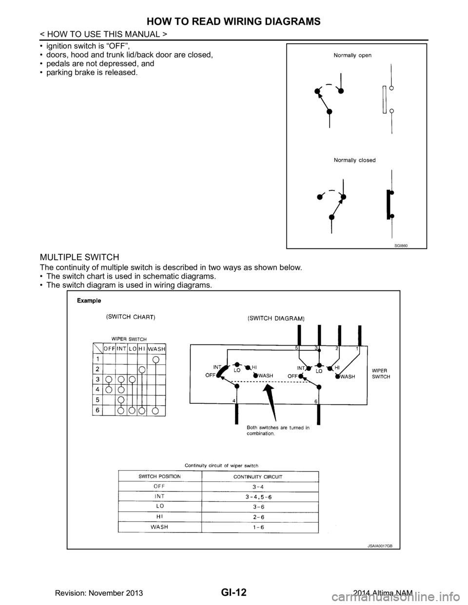
MULTIPLE SWITCH
The continuity of multiple switch is described in two ways as shown below.
• The switch chart is used in schematic diagrams.
• The switch diagram is used in wiring diagrams.
SGI860
JSAIA0017GB
Revision: November 20132014 Altima NAMRevision: November 20132014 Altima NAM
Page 2543 of 4801

ABBREVIATIONSGI-15
< HOW TO USE THIS MANUAL >
C
D E
F
G H
I
J
K L
M B
GI
N
O P
I
K
L
M
N
O
ABBREVIATION DESCRIPTION I/M Inspection and maintenanceIA Intake air
IAC Idle air control IAT Intake air temperature
IBA Intelligent brake assist IC Ignition control
ICC Intelligent cruise control
ICM Ignition control module
IPDM E/R Intelligent power distribution module engine room ISC Idle speed controlISS Input shaft speed ITS Information technology suite
ABBREVIATION DESCRIPTION KS Knock sensor
ABBREVIATION DESCRIPTION LBC Li-ion battery controller
LCD Liquid crystal display
LCU Local control unit LDP Lane departure prevention
LDW Lane departure warning LED Light emitting diode LH Left-hand
LIN Local interconnect network
ABBREVIATION DESCRIPTION M/T Manual transaxle/transmission
MAF Mass airflow
MAP Manifold absolute pressure
MDU Multi display unit MI Malfunction indicator
MIL Malfunction indicator lamp
MOD Moving object detection
ABBREVIATION DESCRIPTION NOX Nitrogen oxides
ABBREVIATION DESCRIPTION O2 Oxygen
O2S Oxygen sensor
OBD On board diagnostic OC Oxidation catalytic converter
OD Overdrive
Revision: November 20132014 Altima NAMRevision: November 20132014 Altima NAM
Page 2554 of 4801
GI-26
< PRECAUTION >
PRECAUTIONS
PRECAUTION
PRECAUTIONS
DescriptionINFOID:0000000009462991
Observe the following precautions to ensure safe and proper servicing. These precautions are not
described in each individual section.
Precaution for Supplemental Restraint Syst em (SRS) "AIR BAG" and "SEAT BELT
PRE-TENSIONER"
INFOID:0000000009462992
The Supplemental Restraint System such as “A IR BAG” and “SEAT BELT PRE-TENSIONER”, used along
with a front seat belt, helps to reduce the risk or severi ty of injury to the driver and front passenger for certain
types of collision. Information necessary to service the system safely is included in the SR and SB section of
this Service Manual.
WARNING:
• To avoid rendering the SRS inopera tive, which could increase the risk of personal injury or death in
the event of a collision which would result in air bag inflation, all maintenance must be performed by
an authorized NISS AN/INFINITI dealer.
• Improper maintenance, including in correct removal and installation of the SRS, can lead to personal
injury caused by unintent ional activation of the system. For re moval of Spiral Cable and Air Bag
Module, see the SR section.
• Do not use electrical test equipmen t on any circuit related to the SRS unless instructed to in this
Service Manual. SRS wiring harn esses can be identified by yellow and/or orange harnesses or har-
ness connectors.
PRECAUTIONS WHEN USING POWER TOOLS (AIR OR ELECTRIC) AND HAMMERS
WARNING:
• When working near the Airbag Diagnosis Sensor Unit or other Airbag System sensors with the Igni-
tion ON or engine running, DO NOT use air or electri c power tools or strike near the sensor(s) with a
hammer. Heavy vibration could activate the sensor( s) and deploy the air bag(s), possibly causing
serious injury.
• When using air or electric power tools or hammers , always switch the Ignition OFF, disconnect the
battery and wait at least 3 minutes before performing any service.
Precautions For Xeno n Headlamp ServiceINFOID:0000000009462993
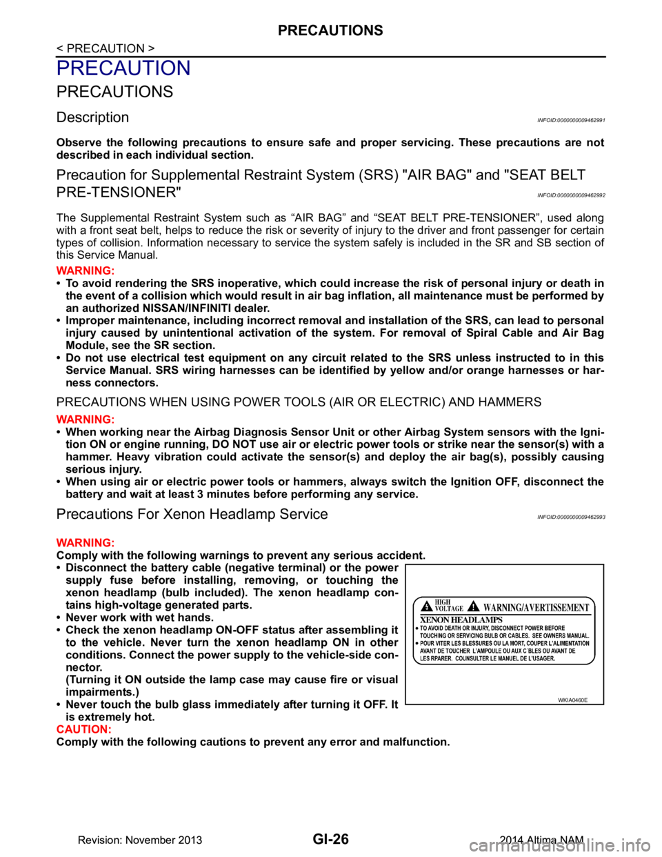
WARNING:
Comply with the following warnings to prevent any serious accident.
• Disconnect the battery cable (n egative terminal) or the power
supply fuse before in stalling, removing, or touching the
xenon headlamp (bulb included) . The xenon headlamp con-
tains high-voltage generated parts.
• Never work with wet hands.
• Check the xenon headlamp ON-OFF status after assembling it to the vehicle. Never turn the xenon headlamp ON in other
conditions. Connect the power supply to the vehicle-side con-
nector.
(Turning it ON outside the la mp case may cause fire or visual
impairments.)
• Never touch the bulb glass immediately after turning it OFF. It is extremely hot.
CAUTION:
Comply with the following cautions to prevent any error and malfunction.
WKIA0460E
Revision: November 20132014 Altima NAMRevision: November 20132014 Altima NAM