2014 NISSAN TEANA ignition
[x] Cancel search: ignitionPage 2365 of 4801
DAYTIME LIGHT RELAY CIRCUITEXL-99
< DTC/CIRCUIT DIAGNOSIS >
C
D E
F
G H
I
J
K
M A
B
EXL
N
O P
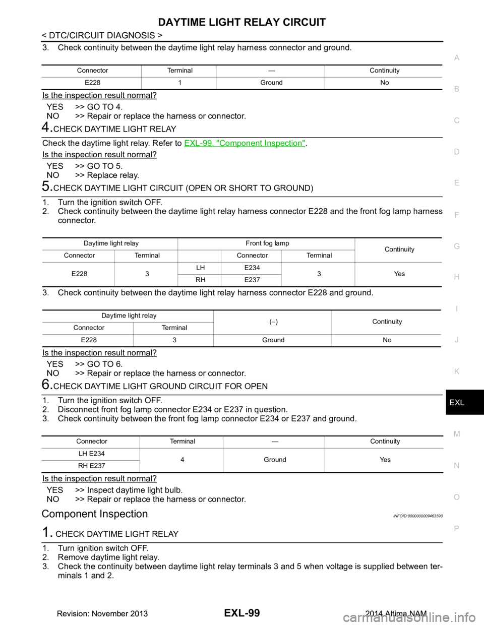
3. Check continuity between the daytime light relay harness connector and ground.
Is the inspection result normal?
YES >> GO TO 4.
NO >> Repair or replace the harness or connector.
4.CHECK DAYTIME LIGHT RELAY
Check the daytime light relay. Refer to EXL-99, "Component Inspection"
.
Is the inspection result normal?
YES >> GO TO 5.
NO >> Replace relay.
5.CHECK DAYTIME LIGHT CIRCUIT (OPEN OR SHORT TO GROUND)
1. Turn the ignition switch OFF.
2. Check continuity between the daytime light rela y harness connector E228 and the front fog lamp harness
connector.
3. Check continuity between the daytime light relay harness connector E228 and ground.
Is the inspection result normal?
YES >> GO TO 6.
NO >> Repair or replace the harness or connector.
6.CHECK DAYTIME LIGHT GROUND CIRCUIT FOR OPEN
1. Turn the ignition switch OFF.
2. Disconnect front fog lamp connector E234 or E237 in question.
3. Check continuity between the front fog lamp connector E234 or E237 and ground.
Is the inspection result normal?
YES >> Inspect daytime light bulb.
NO >> Repair or replace the harness or connector.
Component InspectionINFOID:0000000009463590
1. CHECK DAYTIME LIGHT RELAY
1. Turn ignition switch OFF.
2. Remove daytime light relay.
3. Check the continuity between daytime light relay terminals 3 and 5 when voltage is supplied between ter- minals 1 and 2.
Connector Terminal — Continuity
E228 1 Ground No
Daytime light relay Front fog lamp Continuity
Connector Terminal Connector Terminal
E228 3 LH E234
3Yes
RH E237
Daytime light relay (− )Continuity
Connector Terminal
E228 3 Ground No
Connector Terminal — ContinuityLH E234 4Ground Yes
RH E237
Revision: November 20132014 Altima NAMRevision: November 20132014 Altima NAM
Page 2367 of 4801
FRONT FOG LAMP CIRCUITEXL-101
< DTC/CIRCUIT DIAGNOSIS >
C
D E
F
G H
I
J
K
M A
B
EXL
N
O P
FRONT FOG LAMP CIRCUIT
DescriptionINFOID:0000000009463591
The IPDM E/R (intelligent power di stribution module engine room) controls the front fog lamp relay based on
inputs from the BCM over the CAN communication lines . When the front fog lamp relay is energized, power
flows from the front fog lamp relay in the IPDM E/R to the front fog lamps.
Component Function CheckINFOID:0000000009463592
1.CHECK FRONT FOG LAMP OPERATION
WITHOUT CONSULT
1. Activate IPDM E/R auto active test. Refer to PCS-9, "CONSULT Function (IPDM E/R)"
.
2. Check that the front fog lamp is turned ON.
WITH CONSULT
1. Select EXTERNAL LAMP of IP DM E/R active test item.
2. While operating the test items, check that the front fog lamp is turned ON.
Is the inspection result normal?
YES >> Front fog lamp circuit is normal.
NO >> Refer to EXL-101, "Diagnosis Procedure"
.
Diagnosis ProcedureINFOID:0000000009463593
Regarding Wiring Diagram information, refer to EXL-54, "Wiring Diagram".
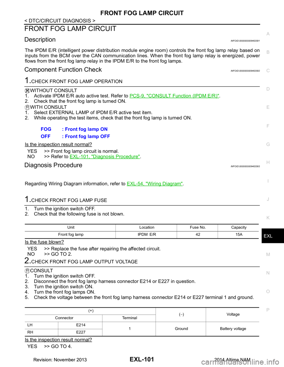
1.CHECK FRONT FOG LAMP FUSE
1. Turn the ignition switch OFF.
2. Check that the following fuse is not blown.
Is the fuse blown?
YES >> Replace the fuse after repairing the affected circuit.
NO >> GO TO 2.
2.CHECK FRONT FOG LAMP OUTPUT VOLTAGE
CONSULT
1. Turn the ignition switch OFF.
2. Disconnect the front fog lamp harness connector E214 or E227 in question.
3. Turn the ignition switch ON.
4. Turn the front fog lamps ON.
5. Check the voltage between the front fog lamp harness connector E214 or E227 terminal 1 and ground.
Is the inspection result normal?
YES >> GO TO 4. FOG : Front fog lamp ON
OFF : Front fog lamp OFF
Unit Location Fuse No. Capacity
Front fog lamp IPDM E/R 42 15A
(+) (− )Voltage
Connector Terminal
LH E214 1 Ground Battery voltage
RH E227
Revision: November 20132014 Altima NAMRevision: November 20132014 Altima NAM
Page 2368 of 4801

EXL-102
< DTC/CIRCUIT DIAGNOSIS >
FRONT FOG LAMP CIRCUIT
NO >> GO TO 3.
3.CHECK FRONT FOG LAMP OPEN CIRCUIT
1. Turn the ignition switch OFF.
2. Disconnect IPDM E/R connector E200.
3. Check continuity between the IPDM E/R harness connector and the front fog lamp harness connector.
Is the inspection result normal?
YES >> Replace IPDM E/R. Refer to PCS-32, "Removal and Installation".
NO >> Repair or replace the harness or connector.
4.CHECK FRONT FOG LAMP GROUND CIRCUIT
Check continuity between the front fog lamp harness connector terminal 2 and ground.
Is the inspection result normal?
YES >> Inspect the fog lamp bulb.
NO >> Repair or replace the harness or connector.
IPDM E/R Front fog lamp Continuity
Connector Terminal Connector Terminal
RH E20078 E227
1Yes
LH 79 E214
Connector Terminal — Continuity
RH E227 2 Ground Yes
LH E214
Revision: November 20132014 Altima NAMRevision: November 20132014 Altima NAM
Page 2369 of 4801
PARKING LAMP CIRCUITEXL-103
< DTC/CIRCUIT DIAGNOSIS >
C
D E
F
G H
I
J
K
M A
B
EXL
N
O P
PARKING LAMP CIRCUIT
DescriptionINFOID:0000000009463594
The IPDM E/R (intelligent power distribution module engi ne room) controls the tail lamp relay based on inputs
from the BCM over the CAN communication lines. When t he tail lamp relay is energized, power flows through
fuses 51 and 52, located in the IPDM E/R. Power then fl ows to the front and rear combination lamps, license
plate lamps.
Component Function CheckINFOID:0000000009463595
1.CHECK PARKING LAMP OPERATION
WITHOUT CONSULT
1. Activate IPDM E/R auto active test. Refer to PCS-8, "Diagnosis Description"
.
2. Check that the parking lamp is turned ON.
WITH CONSULT
1. Select EXTERNAL LAMP of IP DM E/R active test item.
2. While operating the test items, check that the parking lamp is turned ON.
Is the inspection result normal?
YES >> Parking lamp circuit is normal.
NO >> Refer to EXL-103, "Diagnosis Procedure"
.
Diagnosis ProcedureINFOID:0000000009463596
Regarding Wiring Diagram information, refer to EXL-68, "Wiring Diagram".
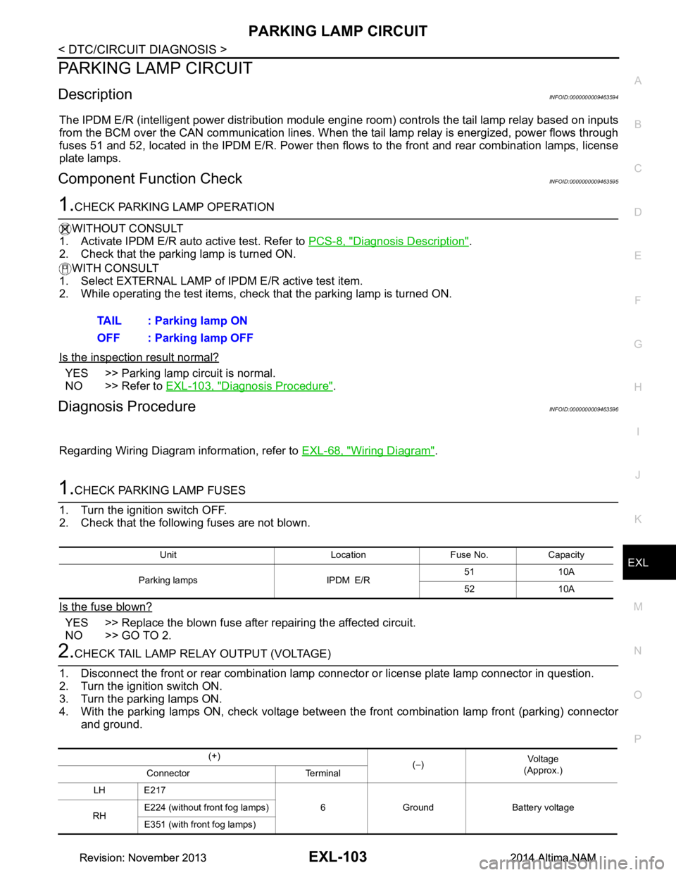
1.CHECK PARKING LAMP FUSES
1. Turn the ignition switch OFF.
2. Check that the following fuses are not blown.
Is the fuse blown?
YES >> Replace the blown fuse after repairing the affected circuit.
NO >> GO TO 2.
2.CHECK TAIL LAMP RELAY OUTPUT (VOLTAGE)
1. Disconnect the front or rear combination lamp connector or license plate lamp connector in question.
2. Turn the ignition switch ON.
3. Turn the parking lamps ON.
4. With the parking lamps ON, check voltage between t he front combination lamp front (parking) connector
and ground. TAIL : Parking lamp ON
OFF : Parking lamp OFF
Unit Location Fuse No. Capacity
Parking lamps IPDM E/R 51 10A
52 10A
(+) (− ) Vo l ta g e
(Approx.)
Connector Terminal
LH E217 6 Ground Battery voltage
RH E224 (without front fog lamps)
E351 (with front fog lamps)
Revision: November 20132014 Altima NAMRevision: November 20132014 Altima NAM
Page 2370 of 4801

EXL-104
< DTC/CIRCUIT DIAGNOSIS >
PARKING LAMP CIRCUIT
5. With the parking lamps ON, check voltage between the front combination lamp (side marker) connector
and ground.
6. With the parking lamps ON, check voltage betw een the rear combination lamp connector and ground.
7. With the parking lamps ON, check voltage between the license plate lamp connector and ground.
Are the inspection results normal?
YES >> GO TO 4.
NO >> GO TO 3.
3.CHECK PARKING LAMP CIRCUIT (OPEN)
1. Turn the ignition switch OFF.
2. Disconnect IPDM E/R connector.
3. Check continuity between the IPDM E/R harness connector and the front combination lamp (parking) har-
ness connector.
4. Check continuity between the IPDM E/R harness connec tor and the front combination lamp (side marker)
harness connector.
5. Check continuity between the IPDM E/R harness c onnector and the rear combination lamp harness con-
nector.
(+) (− ) Vol tag e
(Approx.)
Connector Terminal
LH E235 8 Ground Battery voltage
RH E236
(+) (− ) Vo l ta g e
(Approx.)
Connector Terminal
LH B30 2 Ground Battery voltage
RH B45
(+) (− ) Vo l ta g e
(Approx.)
Connector Terminal
LH B34 1 Ground Battery voltage
RH B32
IPDM E/R Front combination lamp (parking) Continuity
Connector Terminal Connector Terminal
LH E201 90 E217
6Yes
RH E224 (without front fog lamps)
E351 (with front fog lamps)
IPDM E/R Front combination lamp (side marker) Continuity
Connector Terminal Connector Terminal
LH E201 90 E235
8Yes
RH E236
IPDM E/R Rear combination lamp Continuity
Connector Terminal Connector Terminal
Revision: November 20132014 Altima NAMRevision: November 20132014 Altima NAM
Page 2372 of 4801
EXL-106
< DTC/CIRCUIT DIAGNOSIS >
TURN SIGNAL LAMP CIRCUIT
TURN SIGNAL LAMP CIRCUIT
DescriptionINFOID:0000000009463597
The BCM monitors inputs from the combination switch to determine when to activate the turn signals. The
BCM outputs voltage direction to the left and right turn signals during turn signal operation or both during haz-
ard warning operation. The BCM sends a turn signal indicator request to the combination meter via the CAN
communication lines.
The BCM performs the fast flasher operation (fail-safe) if any bulb or harness of the turn signal lamp circuit is
open.
NOTE:
Turn signal lamp blinks at normal speed when using the hazard warning lamp.
Component Function CheckINFOID:0000000009463598
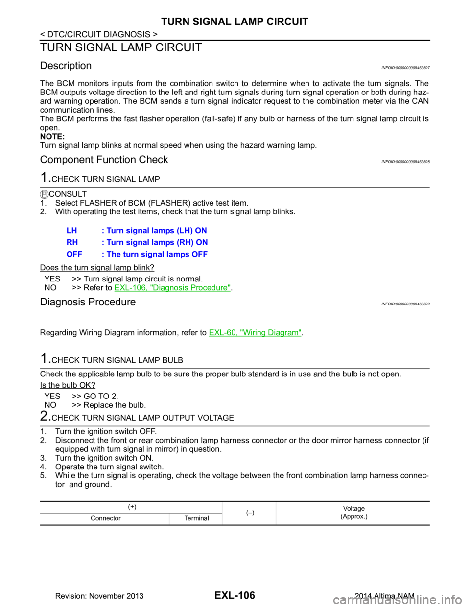
1.CHECK TURN SIGNAL LAMP
CONSULT
1. Select FLASHER of BCM (FLASHER) active test item.
2. With operating the test items, check that the turn signal lamp blinks.
Does the turn signal lamp blink?
YES >> Turn signal lamp circuit is normal.
NO >> Refer to EXL-106, "Diagnosis Procedure"
.
Diagnosis ProcedureINFOID:0000000009463599
Regarding Wiring Diagram information, refer to EXL-60, "Wiring Diagram".
1.CHECK TURN SIGNAL LAMP BULB
Check the applicable lamp bulb to be sure the proper bulb standard is in use and the bulb is not open.
Is the bulb OK?
YES >> GO TO 2.
NO >> Replace the bulb.
2.CHECK TURN SIGNAL LAMP OUTPUT VOLTAGE
1. Turn the ignition switch OFF.
2. Disconnect the front or rear combination lamp har ness connector or the door mirror harness connector (if
equipped with turn signal in mirror) in question.
3. Turn the ignition switch ON.
4. Operate the turn signal switch.
5. While the turn signal is operating, check the vo ltage between the front combination lamp harness connec-
tor and ground. LH : Turn signal lamps (LH) ON
RH : Turn signal lamps (RH) ON
OFF : The turn signal lamps OFF
(+) (− ) Vo l ta g e
(Approx.)
Connector Terminal
Revision: November 20132014 Altima NAMRevision: November 20132014 Altima NAM
Page 2373 of 4801
TURN SIGNAL LAMP CIRCUITEXL-107
< DTC/CIRCUIT DIAGNOSIS >
C
D E
F
G H
I
J
K
M A
B
EXL
N
O P
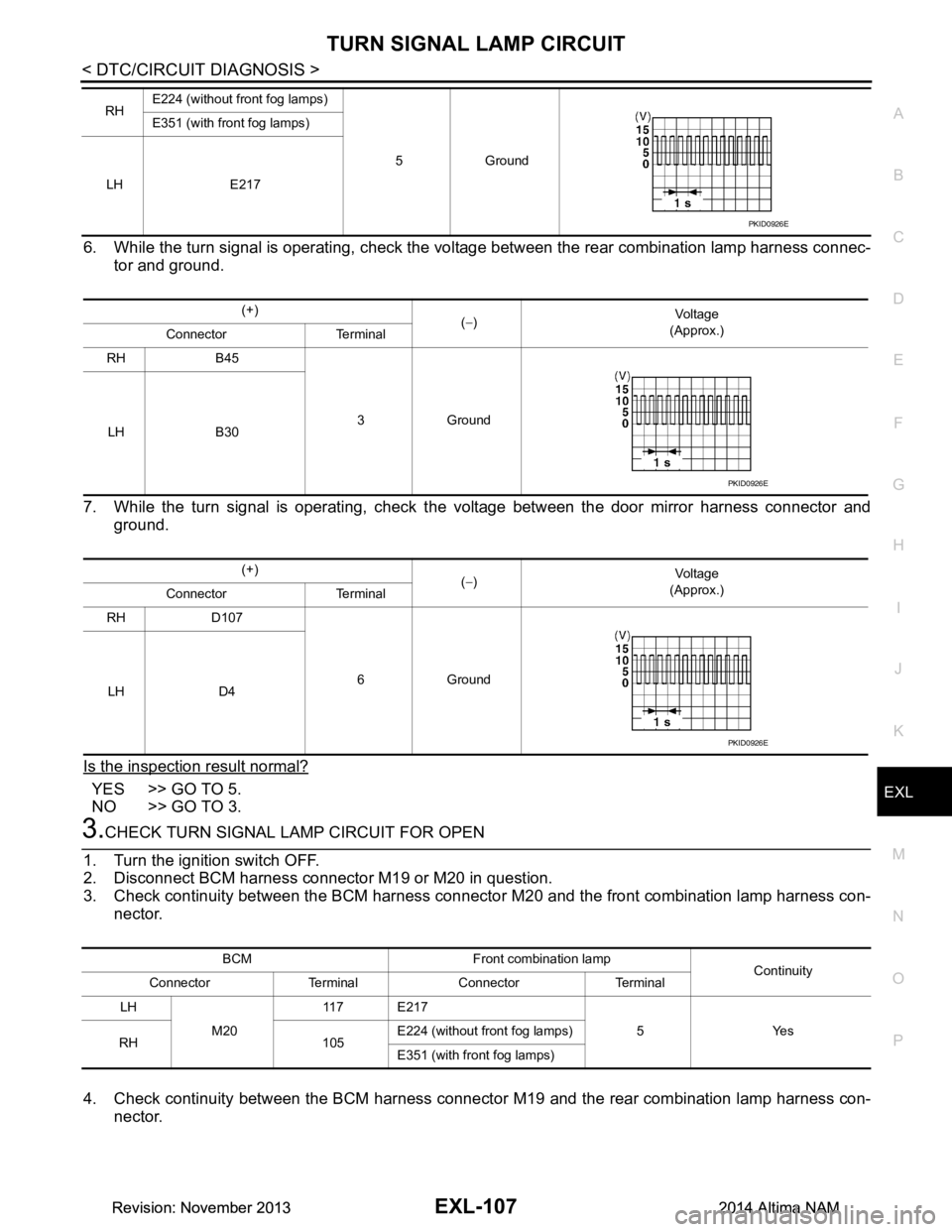
6. While the turn signal is operating, check the vo ltage between the rear combination lamp harness connec-
tor and ground.
7. While the turn signal is operating, check t he voltage between the door mirror harness connector and
ground.
Is the inspection result normal?
YES >> GO TO 5.
NO >> GO TO 3.
3.CHECK TURN SIGNAL LAMP CIRCUIT FOR OPEN
1. Turn the ignition switch OFF.
2. Disconnect BCM harness connector M19 or M20 in question.
3. Check continuity between the BCM harness connecto r M20 and the front combination lamp harness con-
nector.
4. Check continuity between the BCM harness connecto r M19 and the rear combination lamp harness con-
nector.
RH E224 (without front fog lamps)
5Ground
E351 (with front fog lamps)
LH E217
PKID0926E
(+) (− ) Vol tag e
(Approx.)
Connector Terminal
RH B45
3Ground
LH B30
(+) (− ) Vol tag e
(Approx.)
Connector Terminal
RH D107
6Ground
LH D4
PKID0926E
PKID0926E
BCM Front combination lamp Continuity
Connector Terminal Connector Terminal
LH M20 11 7 E 2 1 7
5Yes
RH 105 E224 (without front fog lamps)
E351 (with front fog lamps)
Revision: November 20132014 Altima NAMRevision: November 20132014 Altima NAM
Page 2376 of 4801

EXL-110
< DTC/CIRCUIT DIAGNOSIS >
OPTICAL SENSOR
OPTICAL SENSOR
DescriptionINFOID:0000000009463600
The optical sensor measures ambient light and transmits the optical sensor signal to the BCM.
Component Function CheckINFOID:0000000009463601
1.CHECK OPTICAL SENSOR SIGNAL BY CONSULT
CONSULT
1. Turn the ignition switch ON.
2. Select OPTI SEN of BCM (HEAD LAMP) DATA MONITOR item.
3. Turn the lighting switch to AUTO.
*: Illuminates the optical sensor. The value may be less than the standard value if brightness is weak.
Is the inspection result normal?
YES >> Optical sensor is normal.
NO >> Refer to EXL-110, "Diagnosis Procedure"
.
Diagnosis ProcedureINFOID:0000000009463602
Regarding Wiring Diagram information, refer to EXL-47, "Wiring Diagram".
1.CHECK OPTICAL SENSOR POWER SUPPLY INPUT
1. Turn the ignition switch OFF.
2. Disconnect the optical sensor harness connector M66.
3. Turn the ignition switch ON.
4. Turn the lighting switch to AUTO.
5. Check the voltage between the optical sensor harness connector M66 and ground.
Is the inspection result normal?
YES >> GO TO 2.
NO >> GO TO 3.
2.CHECK OPTICAL SENSOR GROUND CIRCUIT
1. Turn the ignition switch OFF.
2. Check continuity between the optical sensor harness connector M15 and ground.
Is the inspection result normal?
YES >> GO TO 4.
NO >> GO TO 5.
3.CHECK OPTICAL SENSOR POWER SUPPLY FOR OPEN CIRCUIT
1. Turn the ignition switch OFF.
2. Disconnect the BCM harness connector M17.
Monitor item Condition Voltage
OPTI SEN (DTCT) When outside of vehicle is bright 3.1V or more *
When outside of vehicle is dark 0.6V or less
(+) (− ) Vo l ta g e
(Approx.)
Connector Terminal
M66 1 Ground 5 V
(+) (− )Continuity
Connector Terminal
M66 3 Ground Yes
Revision: November 20132014 Altima NAMRevision: November 20132014 Altima NAM