2014 NISSAN TEANA airbag
[x] Cancel search: airbagPage 4086 of 4801

B00D5 PASSENGER AIR BAG OFF INDICATORSRC-93
< DTC/CIRCUIT DIAGNOSIS >
C
D E
F
G
I
J
K L
M A
B
SRC
N
O P
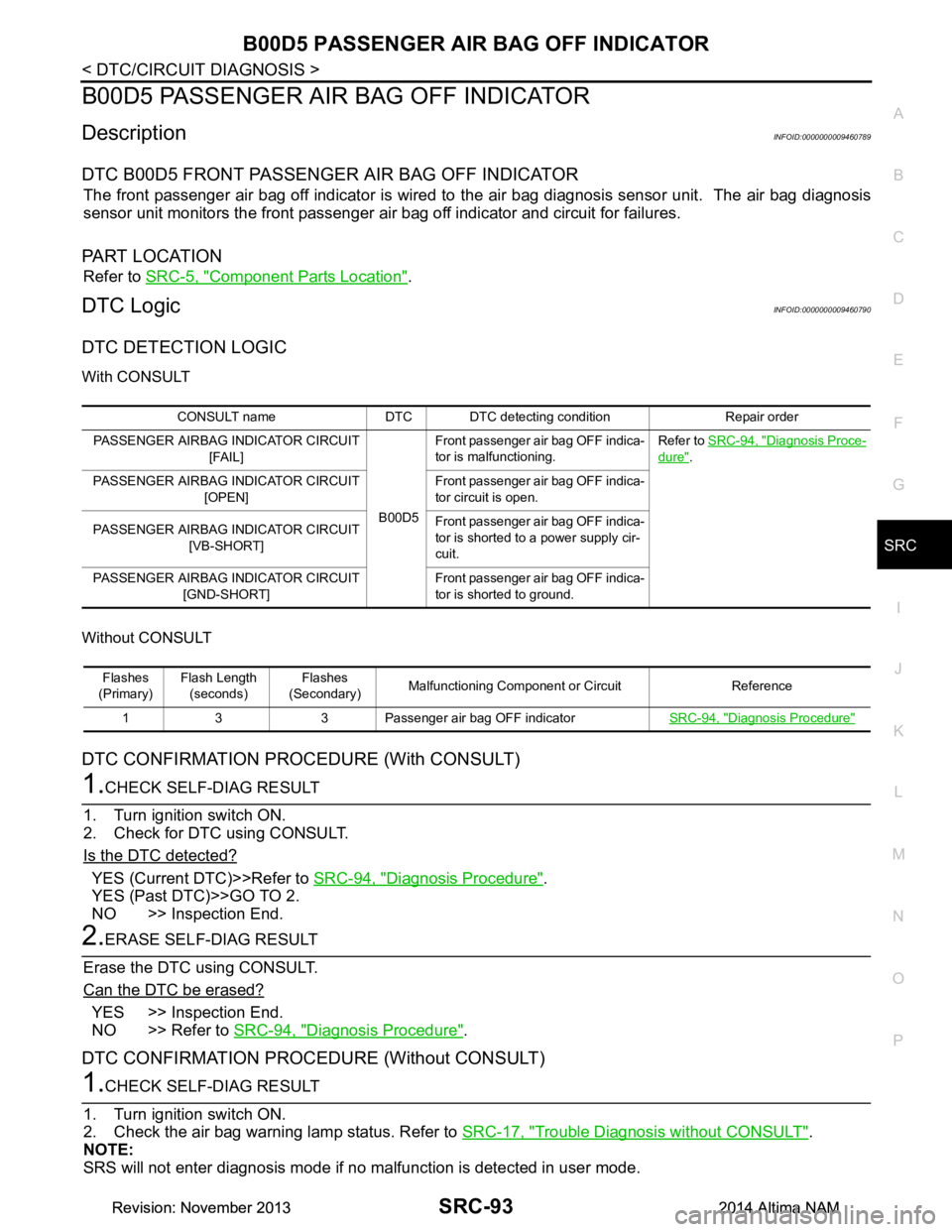
B00D5 PASSENGER AIR BAG OFF INDICATOR
DescriptionINFOID:0000000009460789
DTC B00D5 FRONT PASSENGER AIR BAG OFF INDICATOR
The front passenger air bag off indicator is wired to the air bag diagnosis sensor unit. The air bag diagnosis
sensor unit monitors the front passenger air bag off indicator and circuit for failures.
PA R T L O C AT I O N
Refer to SRC-5, "Component Parts Location".
DTC LogicINFOID:0000000009460790
DTC DETECTION LOGIC
With CONSULT
Without CONSULT
DTC CONFIRMATION PROCEDURE (With CONSULT)
1.CHECK SELF-DIAG RESULT
1. Turn ignition switch ON.
2. Check for DTC using CONSULT.
Is the DTC detected?
YES (Current DTC)>>Refer to SRC-94, "Diagnosis Procedure".
YES (Past DTC)>>GO TO 2.
NO >> Inspection End.
2.ERASE SELF-DIAG RESULT
Erase the DTC using CONSULT.
Can the DTC be erased?
YES >> Inspection End.
NO >> Refer to SRC-94, "Diagnosis Procedure"
.
DTC CONFIRMATION PROCEDURE (Without CONSULT)
1.CHECK SELF-DIAG RESULT
1. Turn ignition switch ON.
2. Check the air bag warning lamp status. Refer to SRC-17, "Trouble Diagnosis without CONSULT"
.
NOTE:
SRS will not enter diagnosis mode if no malfunction is detected in user mode.
CONSULT name DTC DTC detecting condition Repair order
PASSENGER AIRBAG INDICATOR CIRCUIT [FAIL]
B00D5Front passenger air bag OFF indica-
tor is malfunctioning. Refer to
SRC-94, "Diagnosis Proce-
dure".
PASSENGER AIRBAG INDICATOR CIRCUIT [OPEN] Front passenger air bag OFF indica-
tor circuit is open.
PASSENGER AIRBAG INDICATOR CIRCUIT [VB-SHORT] Front passenger air bag OFF indica-
tor is shorted to a power supply cir-
cuit.
PASSENGER AIRBAG INDICATOR CIRCUIT [GND-SHORT] Front passenger air bag OFF indica-
tor is shorted to ground.
Flashes
(Primary) Flash Length
(seconds) Flashes
(Secondary) Malfunctioning Component or Circuit Reference
1 3 3 Passenger air bag OFF indicator SRC-94, "Diagnosis Procedure"
Revision: November 20132014 Altima NAMRevision: November 20132014 Altima NAM
Page 4096 of 4801

B142X COLLISION DETECTIONSRC-103
< DTC/CIRCUIT DIAGNOSIS >
C
D E
F
G
I
J
K L
M A
B
SRC
N
O P
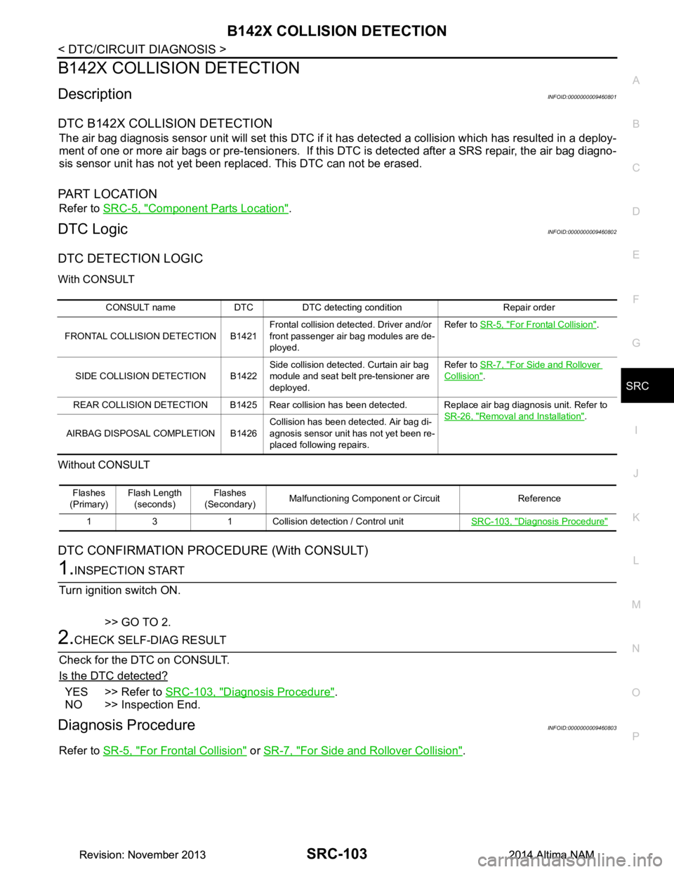
B142X COLLISION DETECTION
DescriptionINFOID:0000000009460801
DTC B142X COLLISION DETECTION
The air bag diagnosis sensor unit will set this DTC if it has detected a collision which has resulted in a deploy-
ment of one or more air bags or pre- tensioners. If this DTC is detected after a SRS repair, the air bag diagno-
sis sensor unit has not yet been replaced. This DTC can not be erased.
PA R T L O C AT I O N
Refer to SRC-5, "Component Parts Location".
DTC LogicINFOID:0000000009460802
DTC DETECTION LOGIC
With CONSULT
Without CONSULT
DTC CONFIRMATION PROCEDURE (With CONSULT)
1.INSPECTION START
Turn ignition switch ON.
>> GO TO 2.
2.CHECK SELF-DIAG RESULT
Check for the DTC on CONSULT.
Is the DTC detected?
YES >> Refer to SRC-103, "Diagnosis Procedure".
NO >> Inspection End.
Diagnosis ProcedureINFOID:0000000009460803
Refer to SR-5, "For Frontal Collision" or SR-7, "For Side and Rollover Collision".
CONSULT name DTC DTC detecting condition Repair order
FRONTAL COLLISION DETECTION B1421 Frontal collision detected. Driver and/or
front passenger air bag modules are de-
ployed. Refer to
SR-5, "For Frontal Collision"
.
SIDE COLLISION DETECTION B1422 Side collision detected. Curtain air bag
module and seat belt pre-tensioner are
deployed. Refer to
SR-7, "For Side and Rollover
Collision".
REAR COLLISION DETECTION B1425 Rear collision has been detected. Replace air bag diagnosis unit. Refer to SR-26, "Removal and Installation"
.
AIRBAG DISPOSAL COMPLETION B1426 Collision has been detected. Air bag di-
agnosis sensor unit has not yet been re-
placed following repairs.
Flashes
(Primary) Flash Length
(seconds) Flashes
(Secondary) Malfunctioning Component or Circuit Reference
1 3 1 Collision detection / Control unit SRC-103, "Diagnosis Procedure"
Revision: November 20132014 Altima NAMRevision: November 20132014 Altima NAM
Page 4106 of 4801

PRECAUTIONSST-3
< PRECAUTION >
C
D E
F
H I
J
K L
M A
B
ST
N
O P
PRECAUTION
PRECAUTIONS
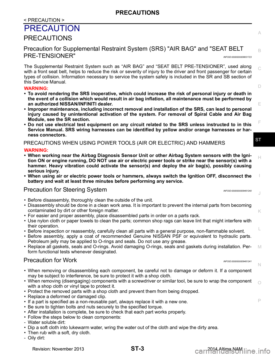
Precaution for Supplemental Restraint System (SRS) "AIR BAG" and "SEAT BELT
PRE-TENSIONER"
INFOID:0000000009951723
The Supplemental Restraint System such as “A IR BAG” and “SEAT BELT PRE-TENSIONER”, used along
with a front seat belt, helps to reduce the risk or severi ty of injury to the driver and front passenger for certain
types of collision. Information necessary to service t he system safely is included in the SR and SB section of
this Service Manual.
WARNING:
• To avoid rendering the SRS inoper ative, which could increase the risk of personal injury or death in
the event of a collision which would result in air bag inflation, all maintenance must be performed by
an authorized NISSAN/INFINITI dealer.
• Improper maintenance, including in correct removal and installation of the SRS, can lead to personal
injury caused by unintentional act ivation of the system. For removal of Spiral Cable and Air Bag
Module, see the SR section.
• Do not use electrical test equipm ent on any circuit related to the SRS unless instructed to in this
Service Manual. SRS wiring harnesses can be identi fied by yellow and/or orange harnesses or har-
ness connectors.
PRECAUTIONS WHEN USING POWER TOOLS (AIR OR ELECTRIC) AND HAMMERS
WARNING:
• When working near the Airbag Diagnosis Sensor Un it or other Airbag System sensors with the Igni-
tion ON or engine running, DO NOT use air or el ectric power tools or strike near the sensor(s) with a
hammer. Heavy vibration could activate the sensor( s) and deploy the air bag(s), possibly causing
serious injury.
• When using air or electric power tools or hammers , always switch the Ignition OFF, disconnect the
battery and wait at least three mi nutes before performing any service.
Precaution for Steering SystemINFOID:0000000009461240
• Before disassembly, thoroughly clean the outside of the unit.
• Disassembly should be done in a clean work area. It is im portant to prevent the internal parts from becoming
contaminated by dirt or other foreign matter.
• For easier and proper assembly, place disassembled parts in order on a parts rack.
• Use nylon cloth or paper towels to clean the parts; common shop rags can leave lint that might interfere with
their operation.
• Before inspection or reassembly, carefully clean al l parts with a general purpose, non-flammable solvent.
• Before assembly, apply a coat of recommended Genuine NISSAN PSF or equivalent to hydraulic parts.
Petroleum jelly may be applied to O-rings and seals. Do not use any grease.
• Replace all gaskets, seals and O-rings. Avoid damaging O-rings, seals and gaskets during installation. Per- form functional tests whenever designated.
Precaution for WorkINFOID:0000000009461241
• When removing or disassembling each component, be ca reful not to damage or deform it. If a component
may be subject to interference, be sure to protect it with a shop cloth.
• When removing (disengaging) components with a screwdriver or similar tool, be sure to wrap the component
with a shop cloth or vinyl tape to protect it.
• Protect the removed parts with a shop cloth and prevent them from being dropped.
• Replace a deformed or damaged clip.
• If a part is specified as a non-reusabl e part, always replace it with a new one.
• Be sure to tighten bolts and nuts securely to the specified torque.
• After installation is complete, be sure to check that each part works properly.
• Follow the steps below to clean components:
- Water soluble dirt:
• Dip a soft cloth into lukewarm water, wring the water out of the cloth and wipe the dirty area.
• Then rub with a soft, dry cloth.
-Oily dirt:
Revision: November 20132014 Altima NAMRevision: November 20132014 Altima NAM
Page 4135 of 4801

ST-32
< REMOVAL AND INSTALLATION >
STEERING WHEEL
• Ensure tick mark on steering wheel is aligned with tick mark on the steering column pin.
• Ensure spiral cable location pin (white rubber pin) is aligned to the steering wheel locating pin hole.
• Route driver airbag module connector(s) and steer ing wheel heater connector harnesses through the
steering wheel.
3. Connect steering wheel switch connector to spiral cable.
4. Connect steering wheel heater connector (from spiral cable) to connector on steering wheel (if equipped).
5. Insert steering wheel heater harness into hook part of the steering wheel back cover.
Revision: November 20132014 Altima NAMRevision: November 20132014 Altima NAM
Page 4154 of 4801

PRECAUTIONSSTC-3
< PRECAUTION >
C
D E
F
H I
J
K L
M A
B
STC
N
O P
PRECAUTION
PRECAUTIONS
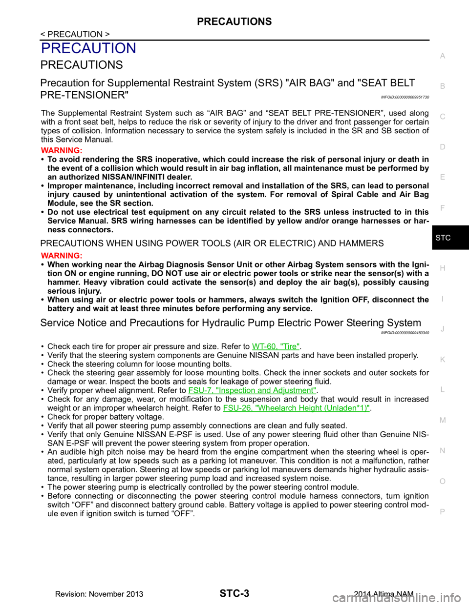
Precaution for Supplemental Restraint System (SRS) "AIR BAG" and "SEAT BELT
PRE-TENSIONER"
INFOID:0000000009951730
The Supplemental Restraint System such as “A IR BAG” and “SEAT BELT PRE-TENSIONER”, used along
with a front seat belt, helps to reduce the risk or severi ty of injury to the driver and front passenger for certain
types of collision. Information necessary to service t he system safely is included in the SR and SB section of
this Service Manual.
WARNING:
• To avoid rendering the SRS inoper ative, which could increase the risk of personal injury or death in
the event of a collision which would result in air bag inflation, all maintenance must be performed by
an authorized NISSAN/INFINITI dealer.
• Improper maintenance, including in correct removal and installation of the SRS, can lead to personal
injury caused by unintentional act ivation of the system. For removal of Spiral Cable and Air Bag
Module, see the SR section.
• Do not use electrical test equipm ent on any circuit related to the SRS unless instructed to in this
Service Manual. SRS wiring harnesses can be identi fied by yellow and/or orange harnesses or har-
ness connectors.
PRECAUTIONS WHEN USING POWER TOOLS (AIR OR ELECTRIC) AND HAMMERS
WARNING:
• When working near the Airbag Diagnosis Sensor Un it or other Airbag System sensors with the Igni-
tion ON or engine running, DO NOT use air or el ectric power tools or strike near the sensor(s) with a
hammer. Heavy vibration could activate the sensor( s) and deploy the air bag(s), possibly causing
serious injury.
• When using air or electric power tools or hammers , always switch the Ignition OFF, disconnect the
battery and wait at least three mi nutes before performing any service.
Service Notice and Precautions for Hydrau lic Pump Electric Power Steering System
INFOID:0000000009460340
• Check each tire for proper air pressure and size. Refer to WT-60, "Tire".
• Verify that the steering system components are G enuine NISSAN parts and have been installed properly.
• Check the steering column for loose mounting bolts.
• Check the steering gear assembly for loose mounting bolts. Check the inner sockets and outer sockets for
damage or wear. Inspect the boots and seals for leakage of power steering fluid.
• Verify proper wheel alignment. Refer to FSU-7, "Inspection and Adjustment"
.
• Check for any damage, wear, or modification to the suspension and body that would result in increased
weight or an improper wheelarch height. Refer to FSU-26, "Wheelarch Height (Unladen*
1)".
• Check for proper battery voltage.
• Verify that all power steering pump assembly connections are clean and fully seated.
• Verify that only Genuine NISSAN E-PSF is used. Use of any power steering fluid other than Genuine NIS-
SAN E-PSF will prevent the power st eering system from proper operation.
• An audible high pitch noise may be heard from the engine compartment when the steering wheel is oper-
ated, particularly at low speeds such as a parking lot maneuver. This condition is not a malfunction, rather
normal system operation. Steering at low speeds or parking lot maneuvers demands higher hydraulic assis-
tance, resulting in larger power st eering pump load and increased system noise.
• The power steering pump is electrically controlled by the power steering control module.
• Before connecting or disconnecting the power steeri ng control module harness connectors, turn ignition
switch “OFF” and disconnect battery ground cable. Batter y voltage is applied to power steering control mod-
ule even if ignition switch is turned “OFF”.
Revision: November 20132014 Altima NAMRevision: November 20132014 Altima NAM
Page 4192 of 4801

STR-2
< PRECAUTION >
PRECAUTIONS
PRECAUTION
PRECAUTIONS
Precaution for Supplemental Restraint System (SRS) "AIR BAG" and "SEAT BELT
PRE-TENSIONER"
INFOID:0000000009951694
The Supplemental Restraint System such as “A IR BAG” and “SEAT BELT PRE-TENSIONER”, used along
with a front seat belt, helps to reduce the risk or severi ty of injury to the driver and front passenger for certain
types of collision. Information necessary to service the system safely is included in the SR and SB section of
this Service Manual.
WARNING:
• To avoid rendering the SRS inopera tive, which could increase the risk of personal injury or death in
the event of a collision which would result in air bag inflation, all maintenance must be performed by
an authorized NISS AN/INFINITI dealer.
• Improper maintenance, including in correct removal and installation of the SRS, can lead to personal
injury caused by unintent ional activation of the system. For re moval of Spiral Cable and Air Bag
Module, see the SR section.
• Do not use electrical test equipmen t on any circuit related to the SRS unless instructed to in this
Service Manual. SRS wiring harn esses can be identified by yellow and/or orange harnesses or har-
ness connectors.
PRECAUTIONS WHEN USING POWER TOOLS (AIR OR ELECTRIC) AND HAMMERS
WARNING:
• When working near the Airbag Diagnosis Sensor Unit or other Airbag System sensors with the Igni-
tion ON or engine running, DO NOT use air or electri c power tools or strike near the sensor(s) with a
hammer. Heavy vibration could activate the sensor( s) and deploy the air bag(s), possibly causing
serious injury.
• When using air or electric power tools or hammers , always switch the Ignition OFF, disconnect the
battery and wait at least three minutes before performing any service.
Revision: November 20132014 Altima NAMRevision: November 20132014 Altima NAM
Page 4224 of 4801
![NISSAN TEANA 2014 Service Manual
PRECAUTIONSTM-9
< PRECAUTION > [CVT: RE0F10D]
C
EF
G H
I
J
K L
M A
B
TM
N
O P
PRECAUTION
PRECAUTIONS
Precaution for Supplemental Restraint System (SRS) "AIR BAG" and "SEAT BELT
PRE-TENSIONER"
INFO NISSAN TEANA 2014 Service Manual
PRECAUTIONSTM-9
< PRECAUTION > [CVT: RE0F10D]
C
EF
G H
I
J
K L
M A
B
TM
N
O P
PRECAUTION
PRECAUTIONS
Precaution for Supplemental Restraint System (SRS) "AIR BAG" and "SEAT BELT
PRE-TENSIONER"
INFO](/manual-img/5/57390/w960_57390-4223.png)
PRECAUTIONSTM-9
< PRECAUTION > [CVT: RE0F10D]
C
EF
G H
I
J
K L
M A
B
TM
N
O P
PRECAUTION
PRECAUTIONS
Precaution for Supplemental Restraint System (SRS) "AIR BAG" and "SEAT BELT
PRE-TENSIONER"
INFOID:0000000009951696
The Supplemental Restraint System such as “A IR BAG” and “SEAT BELT PRE-TENSIONER”, used along
with a front seat belt, helps to reduce the risk or severi ty of injury to the driver and front passenger for certain
types of collision. Information necessary to service t he system safely is included in the SR and SB section of
this Service Manual.
WARNING:
• To avoid rendering the SRS inoper ative, which could increase the risk of personal injury or death in
the event of a collision which would result in air bag inflation, all maintenance must be performed by
an authorized NISSAN/INFINITI dealer.
• Improper maintenance, including in correct removal and installation of the SRS, can lead to personal
injury caused by unintentional act ivation of the system. For removal of Spiral Cable and Air Bag
Module, see the SR section.
• Do not use electrical test equipm ent on any circuit related to the SRS unless instructed to in this
Service Manual. SRS wiring harnesses can be identi fied by yellow and/or orange harnesses or har-
ness connectors.
PRECAUTIONS WHEN USING POWER TOOLS (AIR OR ELECTRIC) AND HAMMERS
WARNING:
• When working near the Airbag Diagnosis Sensor Un it or other Airbag System sensors with the Igni-
tion ON or engine running, DO NOT use air or el ectric power tools or strike near the sensor(s) with a
hammer. Heavy vibration could activate the sensor( s) and deploy the air bag(s), possibly causing
serious injury.
• When using air or electric power tools or hammers , always switch the Ignition OFF, disconnect the
battery and wait at least three mi nutes before performing any service.
Precaution for Procedure without Cowl Top CoverINFOID:0000000009463955
When performing the procedure after removing cowl top cover, cover
the lower end of windshield with urethane, etc to prevent damage to
windshield.
Precaution for TCM and Tran saxle Assembly ReplacementINFOID:0000000009463956
CAUTION:
• To replace TCM, refer to TM-80, "Description"
.
• To replace transaxle assembly, refer to TM-81, "Description"
.
PIIB3706J
Revision: November 20132014 Altima NAMRevision: November 20132014 Altima NAM
Page 4428 of 4801
![NISSAN TEANA 2014 Service Manual
PRECAUTIONSTM-213
< PRECAUTION > [CVT: RE0F10E]
C
EF
G H
I
J
K L
M A
B
TM
N
O P
PRECAUTION
PRECAUTIONS
Precaution for Supplemental Restraint System (SRS) "AIR BAG" and "SEAT BELT
PRE-TENSIONER"
IN NISSAN TEANA 2014 Service Manual
PRECAUTIONSTM-213
< PRECAUTION > [CVT: RE0F10E]
C
EF
G H
I
J
K L
M A
B
TM
N
O P
PRECAUTION
PRECAUTIONS
Precaution for Supplemental Restraint System (SRS) "AIR BAG" and "SEAT BELT
PRE-TENSIONER"
IN](/manual-img/5/57390/w960_57390-4427.png)
PRECAUTIONSTM-213
< PRECAUTION > [CVT: RE0F10E]
C
EF
G H
I
J
K L
M A
B
TM
N
O P
PRECAUTION
PRECAUTIONS
Precaution for Supplemental Restraint System (SRS) "AIR BAG" and "SEAT BELT
PRE-TENSIONER"
INFOID:0000000009951697
The Supplemental Restraint System such as “A IR BAG” and “SEAT BELT PRE-TENSIONER”, used along
with a front seat belt, helps to reduce the risk or severi ty of injury to the driver and front passenger for certain
types of collision. Information necessary to service t he system safely is included in the SR and SB section of
this Service Manual.
WARNING:
• To avoid rendering the SRS inoper ative, which could increase the risk of personal injury or death in
the event of a collision which would result in air bag inflation, all maintenance must be performed by
an authorized NISSAN/INFINITI dealer.
• Improper maintenance, including in correct removal and installation of the SRS, can lead to personal
injury caused by unintentional act ivation of the system. For removal of Spiral Cable and Air Bag
Module, see the SR section.
• Do not use electrical test equipm ent on any circuit related to the SRS unless instructed to in this
Service Manual. SRS wiring harnesses can be identi fied by yellow and/or orange harnesses or har-
ness connectors.
PRECAUTIONS WHEN USING POWER TOOLS (AIR OR ELECTRIC) AND HAMMERS
WARNING:
• When working near the Airbag Diagnosis Sensor Un it or other Airbag System sensors with the Igni-
tion ON or engine running, DO NOT use air or el ectric power tools or strike near the sensor(s) with a
hammer. Heavy vibration could activate the sensor( s) and deploy the air bag(s), possibly causing
serious injury.
• When using air or electric power tools or hammers , always switch the Ignition OFF, disconnect the
battery and wait at least three mi nutes before performing any service.
Precaution for Procedure without Cowl Top CoverINFOID:0000000009464173
When performing the procedure after removing cowl top cover, cover
the lower end of windshield with urethane, etc to prevent damage to
windshield.
Precaution for TCM and Tran saxle Assembly ReplacementINFOID:0000000009464174
CAUTION:
• To replace TCM, refer to TM-282, "Description"
.
• To replace transaxle assembly, refer to TM-283, "Description"
.
PIIB3706J
Revision: November 20132014 Altima NAMRevision: November 20132014 Altima NAM