2014 NISSAN TEANA differential
[x] Cancel search: differentialPage 4 of 4801

< SERVICE DATA AND SPECIFICATIONS (SDS) 2014
QUICK REFERENCE CHART: ALTIMA
QUICK REFERENCE CHART: ALTIMA
Engine Tune-up Data: QR25DEINFOID:0000000010112422
GENERAL SPECIFICATIONS
DRIVE BELTS
SPARK PLUG
Unit: mm (in)
*: Always check with the Parts Department for the latest parts information.
Engine Tune-up Data: VQ35DEINFOID:0000000010112419
GENERAL SPECIFICATIONS
Cylinder arrangement
In-line 4
Displacement cm
3 (in3) 2,488 (151.82)
Bore and stroke mm (in) 89.0 x 100 (3.50 x 3.94)
Valve arrangement DOHC
Firing order 1-3-4-2
Number of piston rings Compression
2
Oil 1
Compression ratio 10.0:1
Compression pressure
kPa (kg/cm
2, psi) / 250 rpm Standard 1410 (14.4, 204.5)
Minimum
1220 (12.4, 176.9)
Differential limit between cylinders 100 (1.0, 14)
Tension of drive belts Auto adjustment by drive belt auto-tensioner
Make DENSO
Type* StandardFXE20HE11C
Gap (nominal) 1.1 (0.043)
Cylinder arrangement V-6
Displacement cm
3 (cu in) 3,498 (213.45)
Bore and stroke mm (in) 95.5 x 81.4 (3.760 x 3.205)
Valve arrangement DOHC
Firing order 1-2-3-4-5-6
Number of piston rings Compression 2
Oil 1
Number of main bearings 4
Compression ratio 10.3:1
Compression pressure
kPa (kg/cm
2, psi)/300 rpm Standard 1,275 (13.0, 185)
Minimum
981 (10.0, 142)
Differential limit between cylinders 98 (1.0, 14)
Page 169 of 4801
![NISSAN TEANA 2014 Service Manual
SYSTEMBRC-23
< SYSTEM DESCRIPTION > [VDC/TCS/ABS]
C
D E
G H
I
J
K L
M A
B
BRC
N
O P
VDC/TCS/ABS : VDC FunctionINFOID:0000000009463753
SYSTEM DIAGRAM
SYSTEM DESCRIPTION
• Side slip or tail slip m NISSAN TEANA 2014 Service Manual
SYSTEMBRC-23
< SYSTEM DESCRIPTION > [VDC/TCS/ABS]
C
D E
G H
I
J
K L
M A
B
BRC
N
O P
VDC/TCS/ABS : VDC FunctionINFOID:0000000009463753
SYSTEM DIAGRAM
SYSTEM DESCRIPTION
• Side slip or tail slip m](/manual-img/5/57390/w960_57390-168.png)
SYSTEMBRC-23
< SYSTEM DESCRIPTION > [VDC/TCS/ABS]
C
D E
G H
I
J
K L
M A
B
BRC
N
O P
VDC/TCS/ABS : VDC FunctionINFOID:0000000009463753
SYSTEM DIAGRAM
SYSTEM DESCRIPTION
• Side slip or tail slip may occur while driving on a slippery road or intending an urgent evasive driving maneu- ver. VDC function detects side slip status using each s ensor when side slip or tail slip is about to occur and
improves vehicle stability by brake c ontrol and engine output control during driving.
• In addition to ABS function, EBD function and TCS functi on, target side slip amount is calculated according
to steering operation amount from steering angle sensor. By comparing this information with vehicle side slip
amount that is calculated from information from yaw rate/side G sensor and wheel sensor, vehicle driving
conditions (conditions of understeer or oversteer) are judged and vehicle stability is improved by brake force
control on all 4 wheels and engine output control.
• VDC function can be switched to non-operational status (OFF) by operating VDC OFF switch. In this case,
VDC OFF indicator lamp turns ON.
• Control unit portion automatically improves driving st ability by performing brake force control as well as
engine output control, by transmitting drive signal to actuator portion according to difference between target
side slip amount and vehicle side slip amount
Brake limited slip differential (BLSD) function
is malfunctioning OFF OFF
VDC function is operating OFF OFF
TCS function is operating OFF OFF Condition (status) ABS warnin
g lamp Brake warning lamp
ALFIA0298GB
JSFIA0672GB
Revision: November 20132014 Altima NAMRevision: November 20132014 Altima NAM
Page 2109 of 4801
![NISSAN TEANA 2014 Service Manual
SERVICE DATA AND SPECIFICATIONS (SDS)EM-111
< SERVICE DATA AND SPECIFICATIONS (SDS) [QR25DE]
C
D E
F
G H
I
J
K L
M A
EM
NP
O
SERVICE DATA AND SPECIFICATIONS (SDS)
SERVICE DATA AND SPECIFICATIONS (S NISSAN TEANA 2014 Service Manual
SERVICE DATA AND SPECIFICATIONS (SDS)EM-111
< SERVICE DATA AND SPECIFICATIONS (SDS) [QR25DE]
C
D E
F
G H
I
J
K L
M A
EM
NP
O
SERVICE DATA AND SPECIFICATIONS (SDS)
SERVICE DATA AND SPECIFICATIONS (S](/manual-img/5/57390/w960_57390-2108.png)
SERVICE DATA AND SPECIFICATIONS (SDS)EM-111
< SERVICE DATA AND SPECIFICATIONS (SDS) [QR25DE]
C
D E
F
G H
I
J
K L
M A
EM
NP
O
SERVICE DATA AND SPECIFICATIONS (SDS)
SERVICE DATA AND SPECIFICATIONS (SDS)
Standard and LimitINFOID:0000000009460513
GENERAL SPECIFICATIONS
VA LV E T I M I N G
Unit: degree
*1: When running at idle with engine coolant temperature more than 60
°C (140 °F).
Cylinder arrangement
In-line 4
Displacement cm
3 (in3) 2,488 (151.82)
Bore and stroke mm (in) 89.0 x 100 (3.50 x 3.94)
Valve arrangement DOHC
Firing order 1-3-4-2
Number of piston rings Compression 2
Oil 1
Compression ratio 10.0:1
Compression pressure
kPa (kg/cm
2, psi) / 250 rpm Standard 1410 (14.4, 204.5)
Minimum 1220 (12.4, 176.9)
Differential limit between cylinders 100 (1.0, 14)
Va l v e t i m i n g : Intake valve
: Exhaust valve
ab c de f
VTC Minimum phasing
(Mechanical)
*1224 244 5 69 3 41
VTC Maximum phasing
(Mechanical)
*2224 244 35 29 48 4
Intermediate lock phasing
(Mechanical)
*3224 244 5 59 3 41
ALBIA0875GBALBIA0876GB
ALBIA0877GB
Revision: November 20132014 Altima NAM
Page 2244 of 4801
![NISSAN TEANA 2014 Service Manual
EM-246
< SERVICE DATA AND SPECIFICATIONS (SDS) [VQ35DE]
SERVICE DATA AND SPECIFICATIONS (SDS)
SERVICE DATA AND SPECIFICATIONS (SDS)
SERVICE DATA AND SPECIFICATIONS (SDS)
General SpecificationINFOID:0 NISSAN TEANA 2014 Service Manual
EM-246
< SERVICE DATA AND SPECIFICATIONS (SDS) [VQ35DE]
SERVICE DATA AND SPECIFICATIONS (SDS)
SERVICE DATA AND SPECIFICATIONS (SDS)
SERVICE DATA AND SPECIFICATIONS (SDS)
General SpecificationINFOID:0](/manual-img/5/57390/w960_57390-2243.png)
EM-246
< SERVICE DATA AND SPECIFICATIONS (SDS) [VQ35DE]
SERVICE DATA AND SPECIFICATIONS (SDS)
SERVICE DATA AND SPECIFICATIONS (SDS)
SERVICE DATA AND SPECIFICATIONS (SDS)
General SpecificationINFOID:0000000009460584
GENERAL SPECIFICATIONS
Drive BeltINFOID:0000000009460585
DRIVE BELT
Cylinder arrangement
V-6
Displacement cm
3 (cu in) 3,498 (213.45)
Bore and stroke mm (in) 95.5 x 81.4 (3.760 x 3.205)
Valve arrangement DOHC
Firing order 1-2-3-4-5-6
Number of piston rings Compression 2
Oil 1
Number of main bearings 4
Compression ratio 10.3:1
Compression pressure
kPa (kg/cm
2, psi)/300 rpm Standard 1,275 (13.0, 185)
Minimum 981 (10.0, 142)
Differential limit between cylinders 98 (1.0, 14)
Cylinder number
Valve timing
(Valve timing control - “OFF”)
Unit: degree
abcde f
240 240 −
10 (-35)
AT D C 70(25)
ABDC 10 50
SEM713A
PBIC0187E
Revision: November 20132014 Altima NAM
Page 2455 of 4801

PREPARATIONFAX-3
< PREPARATION >
CEF
G H
I
J
K L
M A
B
FA X
N
O P
PREPARATION
PREPARATION
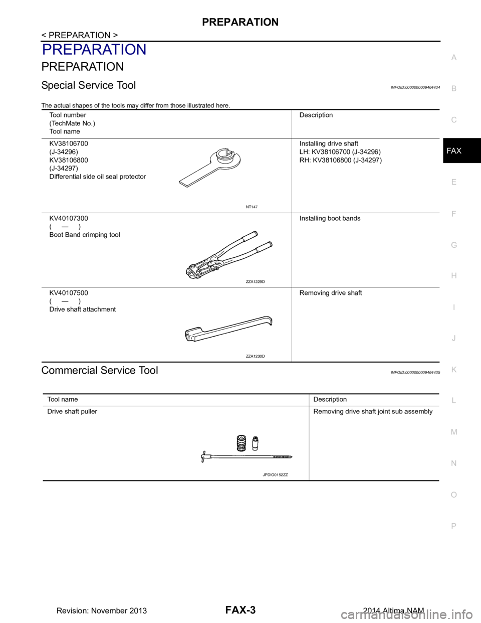
Special Service ToolINFOID:0000000009464434
The actual shapes of the tools may differ from those illustrated here.
Commercial Service ToolINFOID:0000000009464435
Tool number
(TechMate No.)
Tool name Description
KV38106700
(J-34296)
KV38106800
(J-34297)
Differential side oil seal protector Installing drive shaft
LH: KV38106700 (J-34296)
RH: KV38106800 (J-34297)
KV40107300
(—)
Boot Band crimping tool Installing boot bands
KV40107500
(—)
Drive shaft attachment Removing drive shaft
NT147
ZZA1229D
ZZA1230D
Tool name
Description
Drive shaft puller Removing drive shaft joint sub assembly
JPDIG0152ZZ
Revision: November 20132014 Altima NAM
Page 2463 of 4801

FRONT DRIVE SHAFTFAX-11
< REMOVAL AND INSTALLATION >
CEF
G H
I
J
K L
M A
B
FA X
N
O P
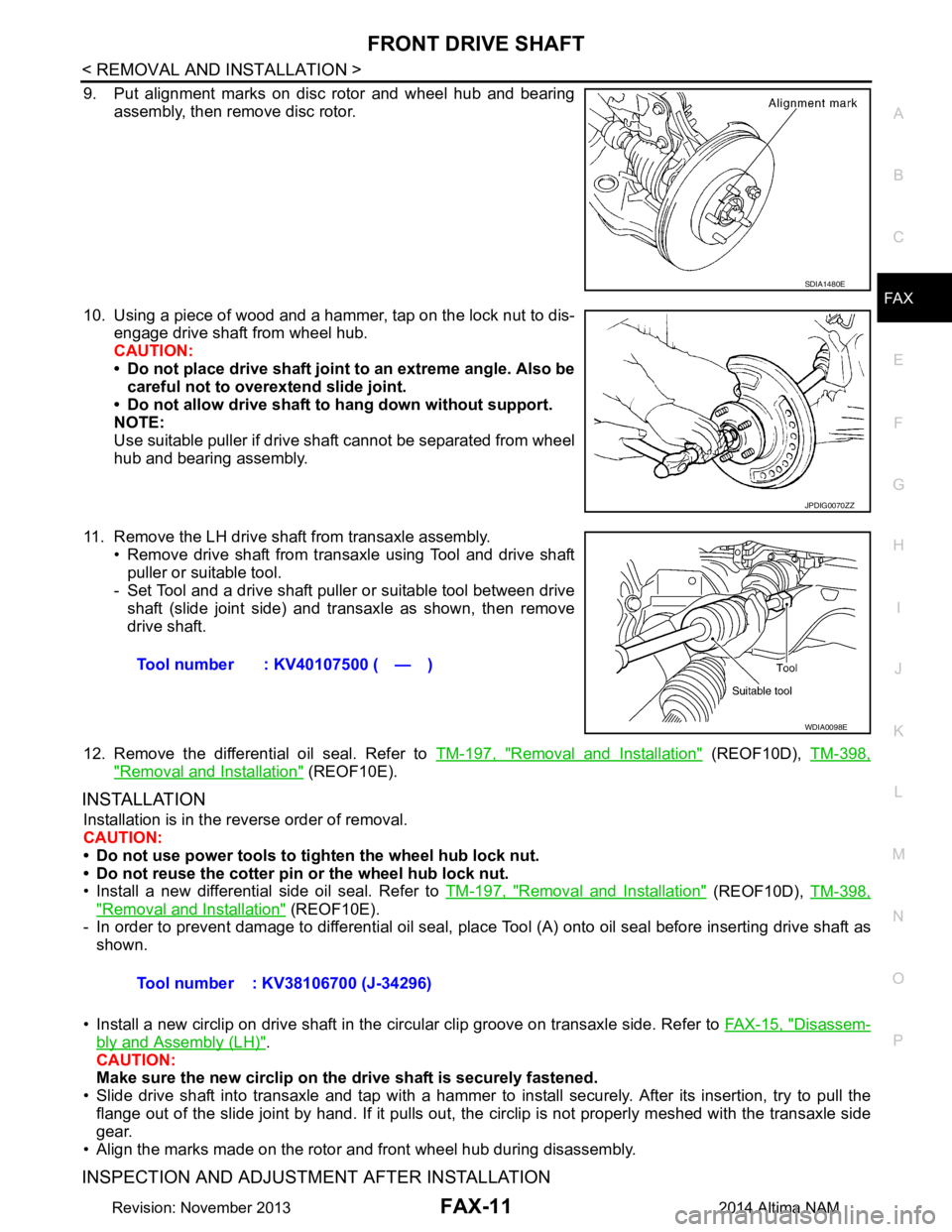
9. Put alignment marks on disc rotor and wheel hub and bearing assembly, then remove disc rotor.
10. Using a piece of wood and a hammer, tap on the lock nut to dis- engage drive shaft from wheel hub.
CAUTION:
• Do not place drive shaft joint to an extreme angle. Also be careful not to over extend slide joint.
• Do not allow drive shaft to hang down without support.
NOTE:
Use suitable puller if drive shaft cannot be separated from wheel
hub and bearing assembly.
11. Remove the LH drive shaf t from transaxle assembly.
• Remove drive shaft from transaxle using Tool and drive shaft puller or suitable tool.
- Set Tool and a drive shaft puller or suitable tool between drive
shaft (slide joint side) and transaxle as shown, then remove
drive shaft.
12. Remove the differential oil seal. Refer to TM-197, "Removal and Installation"
(REOF10D), TM-398,
"Removal and Installation" (REOF10E).
INSTALLATION
Installation is in the reverse order of removal.
CAUTION:
• Do not use power tools to ti ghten the wheel hub lock nut.
• Do not reuse the cotter pin or the wheel hub lock nut.
• Install a new differential side oil seal. Refer to TM-197, "Removal and Installation"
(REOF10D), TM-398,
"Removal and Installation" (REOF10E).
- In order to prevent damage to differential oil seal, plac e Tool (A) onto oil seal before inserting drive shaft as
shown.
• Install a new circlip on drive shaft in the circular clip groove on transaxle side. Refer to FAX-15, "Disassem-
bly and Assembly (LH)".
CAUTION:
Make sure the new circlip on the drive shaft is securely fastened.
• Slide drive shaft into transaxle and tap with a hammer to install securely. After its insertion, try to pull the
flange out of the slide joint by hand. If it pulls out, t he circlip is not properly meshed with the transaxle side
gear.
• Align the marks made on the rotor and front wheel hub during disassembly.
INSPECTION AND ADJUSTMENT AFTER INSTALLATION
SDIA1480E
JPDIG0070ZZ
Tool number : KV40107500 ( — )
WDIA0098E
Tool number : KV38106700 (J-34296)
Revision: November 20132014 Altima NAM
Page 2465 of 4801

FRONT DRIVE SHAFTFAX-13
< REMOVAL AND INSTALLATION >
CEF
G H
I
J
K L
M A
B
FA X
N
O P
3. Remove brake hose retaining clip and brake hose from strut.
4. Remove and discard cotter pin from drive shaft.
5. Remove nut retainer from drive shaft.
6. Loosen lock nut from drive shaft using power tool.
7. Remove brake caliper using power tool, leaving hy draulic brake hose attached. Position caliper aside
using wire. Refer to BR-36, "BRAKE CALIPER ASSEMBLY : Removal and Installation"
.
CAUTION:
• Do not twist or stretch the brake hose.
• Do not depress brake pedal while brake caliper is removed.
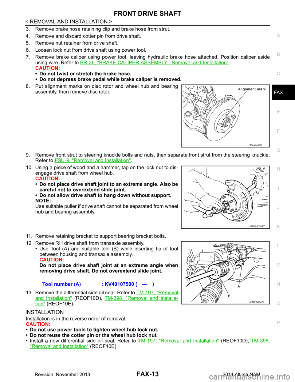
8. Put alignment marks on disc rotor and wheel hub and bearing assembly, then remove disc rotor.
9. Remove front strut to steering knuckle bolts and nuts, then separate front strut from the steering knuckle.
Refer to FSU-9, "Removal and Installation"
.
10. Using a piece of wood and a hammer, tap on the lock nut to dis- engage drive shaft from wheel hub.
CAUTION:
• Do not place drive shaft joint to an extreme angle. Also be careful not to over extend slide joint.
• Do not allow drive shaft to hang down without support.
NOTE:
Use suitable puller if drive shaft cannot be separated from wheel
hub and bearing assembly.
11. Remove retaining bracket to support bearing bracket bolts.
12. Remove RH drive shaft from transaxle assembly. • Use Tool (A) and suitable tool (B) while inserting tip of tool
between housing and transaxle assembly.
CAUTION:
Do not place drive shaft join t at an extreme angle when
removing drive shaft. Do not overextend slide joint.
13. Remove the differential side oil seal. Refer to TM-197, "Removal
and Installation" (REOF10D), TM-398, "Removal and Installa-
tion" (REOF10E).
INSTALLATION
Installation is in the reverse order of removal.
CAUTION:
• Do not use power tools to tighten wheel hub lock nut.
• Do not reuse the cotter pin or the wheel hub lock nut.
• Install a new differential side oil seal. Refer to TM-197, "Removal and Installation"
(REOF10D), TM-398,
"Removal and Installation" (REOF10E).
SDIA1480E
JPDIG0070ZZ
Tool number (A) : KV40107500 ( — )
JPDIF0004ZZ
Revision: November 20132014 Altima NAM
Page 2466 of 4801

FAX-14
< REMOVAL AND INSTALLATION >
FRONT DRIVE SHAFT
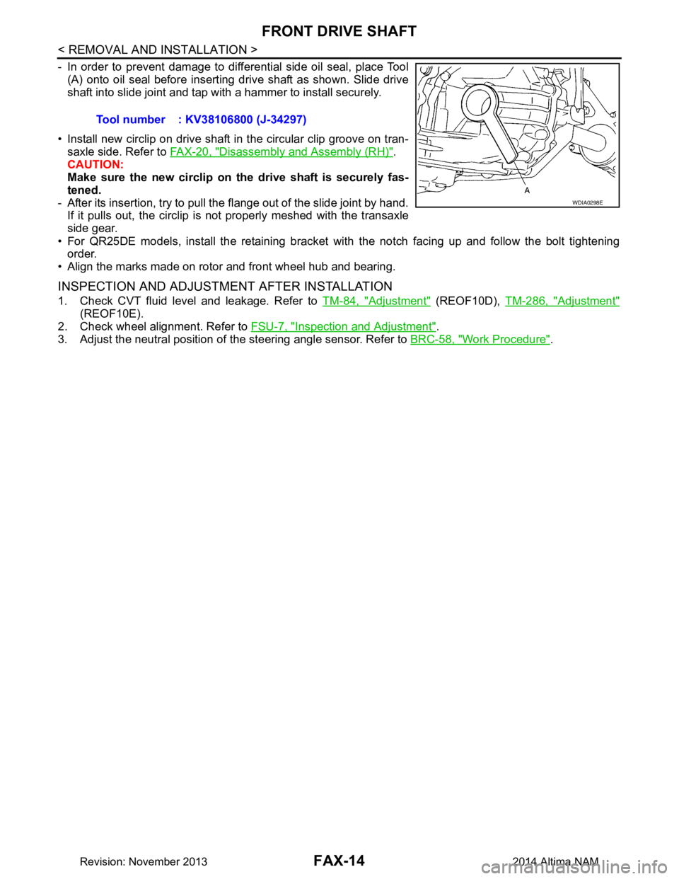
- In order to prevent damage to differential side oil seal, place Tool(A) onto oil seal before inserting drive shaft as shown. Slide drive
shaft into slide joint and tap with a hammer to install securely.
• Install new circlip on drive shaft in the circular clip groove on tran- saxle side. Refer to FAX-20, "Disassembly and Assembly (RH)"
.
CAUTION:
Make sure the new circlip on the drive shaft is securely fas-
tened.
- After its insertion, try to pull the flange out of the slide joint by hand. If it pulls out, the circlip is not properly meshed with the transaxle
side gear.
• For QR25DE models, install the retaining bracket with the notch facing up and follow the bolt tightening
order.
• Align the marks made on rotor and front wheel hub and bearing.
INSPECTION AND ADJUSTMENT AFTER INSTALLATION
1. Check CVT fluid level and leakage. Refer to TM-84, "Adjustment" (REOF10D), TM-286, "Adjustment"
(REOF10E).
2. Check wheel alignment. Refer to FSU-7, "Inspection and Adjustment"
.
3. Adjust the neutral position of the steering angle sensor. Refer to BRC-58, "Work Procedure"
.
Tool number : KV38106800 (J-34297)
WDIA0298E
Revision: November 20132014 Altima NAM