Page 305 of 362
![MITSUBISHI L200 2014 Owners Manual (in English) Before fitting tyre chains, we recommend you to
consult a MITSUBISHI MOTORS Authorized Serv-
ice Point. The max. chain height is as follows.Tyre sizeWheel sizeMax. chain
height [mm]195R15C,
MITSUBISHI L200 2014 Owners Manual (in English) Before fitting tyre chains, we recommend you to
consult a MITSUBISHI MOTORS Authorized Serv-
ice Point. The max. chain height is as follows.Tyre sizeWheel sizeMax. chain
height [mm]195R15C,](/manual-img/19/34876/w960_34876-304.png)
Before fitting tyre chains, we recommend you to
consult a MITSUBISHI MOTORS Authorized Serv-
ice Point. The max. chain height is as follows.Tyre sizeWheel sizeMax. chain
height [mm]195R15C,
215/70R15C *15x6 JJ
22
205R16C16x6 JJ205/80R1616x6 JJ245/70R1616x7 J245/65R1717x7 1/2 J*
: 215/70R15C size should only be used as snow
tyres.
The speed limit for tyre chain is 50 km/h (30 mph)
and remove the tyre chains as soon as possible on
snow free roads.
WARNINGl DO NOT use a jack when fitting the
chains, as in thsee conditions, the tyres
may slip on the icy road causing the vehi-
cle to slip off the jack.CAUTIONl Practice fitting the chains before you
need them.
Don’t expect help from other people in
the cold.
l Choose a clear straight stretch of road
where you can pull over and still be seen
while you are fitting the chains.CAUTIONl Do not fit chains before you need them.
This will wear out your tyres and the
road surface.
l After driving around 100-300 metres
,
stop and retighten the chains.
l Drive carefully and do not exceed
50 km/h (30 mph). Remember, fitting
chains is not going to stop accidents from
happening.
l When tyre chains are installed, take care
that they do not damage the disc wheel or
body.
l An aluminium wheel can be damaged by
a tyre chain while driving. When fitting a
tyre chain on an aluminium wheel, take
care that any part of the chain and fitting
cannot be brought into contact with the
wheel.
l When installing or removing the tyre
chains, take care that hands and other
parts of your body are not injured by the
sharp edges of the vehicle body.
l Install the chains only on the rear tyres
and tighten them as tightly as possible
with the ends securely fastened.
NOTE
l The laws and regulations concerning the use
of tyre chains vary. Find out and follow the
laws and regulations of the area you’re driv-
ing in.
In most countries, it is prohibited by law to
use tyre chains on roads without snow.
Clutch pedal free play* E01002200222
Press down the clutch pedal with your fingers until
initial resistance is felt.
This distance should be within the specified range.
A- Free play: 4 to 13 mm
If the clutch pedal free play is not within the stand-
ard range, we recommend you to have it checked.
Maintenance
8-15
OKTE14E2
8
Page 306 of 362

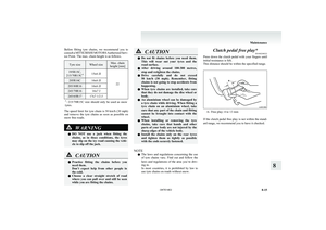
Brake pedal free playE01002300281
Stop the engine, depress the brake pedal several
times, and press down the pedal with your fingers
until initial resistance is felt. This distance should
be within the specified range.
A- Free play: 3 to 8 mm
If the brake pedal free play is not within the stand-
ard range, we recommend you to have it checked.
Parking brake lever stroke E01002400527
Pull the parking brake lever up to check the num-
ber of “clicks” that the ratchet makes. One click rep-
resents a lever movement of one notch. The lever
should move the specified number of notches for
normal brake application.
Type 1AType 2 (LHD)Type 2 (RHD)
A- Parking brake lever stroke Type 1 8 to 9 notches
Type 2 11 to 13 notches
( Parking brake adjustment when pulled with
the force of 200 N)
If the parking brake lever stroke is out of the stand-
ard range, we recommend you to have it checked.
WARNINGl Continued operation of the vehicle with
the parking brake lever out of adjust-
ment may result in the vehicle moving
when unattended.
Maintenance
8-16 OKTE14E2
8
Page 307 of 362

Wiper bladesE01002600385
When lifting the wiper arms off the windscreen,
first raise the driver’s side wiper arm and then the
passenger’s side wiper arm.
When returning them to their original positions,
first put the passenger’s side wiper arm back in
place and then the driver’s side wiper arm.
If the blades are frozen to the windscreen, do not
operate the wipers until the ice has melted and the
blades are freed, otherwise the wiper motor may be
damaged.
Wiper blade rubber replacement
Driver’s side 1. Lift the wiper arm off the windscreen.
2. Pull the wiper blade until its stopper (A) dis-
engages from the hook (B). Then, pull the
wiper blade further to remove it.
NOTE
l Do not allow the wiper arm to fall onto the
windscreen; it could damage the glass.
3. Attach the retainers (C) to a new wiper blade.
For LHD vehicles refer to the illustration to
ensure that the retainers are correctly aligned
as you attach them.LHDRHD
4. Insert the wiper blade into the arm, starting
with the opposite end of the blade from the
stopper. Make sure the hook (B) is fitted cor-
rectly in the grooves in the blade.
NOTE
l If retainers are not supplied with the new wip-
er blade, use the retainers from the old blade.
5. Push the wiper blade until the hook (B) en-
gages securely with the stopper (A).
Passenger’s side
1. Lift the wiper arm off the windscreen.
2. Pull the wiper blade until its stopper (A) dis-
engages from the hook (B). Then, pull the
wiper blade further to remove it.
Maintenance
8-17
OKTE14E2
8
Page 308 of 362

NOTEl Do not allow the wiper arm to fall onto the
windscreen; it could damage the glass.
3. Attach the retainers (C) to a new wiper blade.
Refer to the illustration to ensure that the re-
tainers are correctly aligned as you attach
them.
4. Insert the wiper blade into the arm, starting
with the opposite end of the blade from the
stopper. Make sure the hook (B) is fitted cor-
rectly in the grooves in the blade.
NOTE l If retainers are not supplied with the new wip-
er blade, use the retainers from the old blade.
5. Push the wiper blade until the hook (B) en-
gages securely with the stopper (A).General maintenance E01002700113
Fuel, engine coolant, oil and exhaust
gas leakage
Look under the body of your vehicle to check for
fuel, engine coolant, oil and exhaust gas leaks.WARNINGl If you see a suspicious fuel leak or if you
smell fuel, do not operate the vehicle; we
recommend you to call for assistance.
Exterior and interior lamp operation
Operate the combination lamp switch to check that
all lamps are functioning properly.
If the lamps do not illuminate, the probable cause
is a blown fuse or defective lamp bulb. Check the
fuses first. If there is no blown fuses, check the
lamp bulbs.
For information regarding the inspection and re-
placement of the fuses and the lamp bulbs, refer to
“ Fuses” on page 8-20 and “Replacement of lamp
bulbs” on page 8-23.
If the fuses and bulbs are all OK, we recommend
you to have your vehicle checked and repaired.
Meter, gauge and indicator/warning
lamps operation
Run the engine to check the operation of all meters,
gauges, and indicator/warning lamps.
If there is anything wrong, we recommend you to
have your vehicle inspected.
Maintenance
8-18 OKTE14E2
8
Page 309 of 362

Hinges and latches lubrication
Check all latches and hinges, and lubricate if neces-
sary by first cleaning and then applying multipur-
pose grease.For cold and snowy weather E01002800257
Ventilation slots
The ventilation slots in front of the windscreen
should be kept clear of leaves or brushed clear after
heavy snowfall, so that the operation of the heating
and ventilation systems will not be impaired.
Weatherstripping
To prevent freezing of the weatherstripping on the
doors, bonnet, etc., they should be treated with sili-
cone grease or spray.
Additional equipment
It is a good idea to carry a shovel or a short-han-
dled spade in the vehicle during the winter so that
you can clear away snow if you get stranded. A
small hand-brush for sweeping snow off the vehi-
cle and a plastic scraper for the windscreen and
rear window are also useful.Fusible links E01002900030
The fusible links will melt to prevent a fire if a
large current attempts to flow through certain elec-
trical systems.
In case of a melted fusible link, we recommend
you to have your vehicle inspected.
Maintenance
8-19
OKTE14E2
8
Page 310 of 362

FusesE01003000849Fuse block location E01007600032
To prevent damage to the electrical system due to
shortcircuiting or overloading, each individual cir-
cuit is provided with a fuse.
There are fuse blocks in the passenger compart-
ment and in the engine compartment.
Passenger compartment
The fuse block in the passenger compartment is lo-
cated in front of the driver’s seat at the position
shown in the illustration.
Engine compartment
In the engine compartment, the fuse block is loca-
ted as shown in the illustration.
1- Push the knob.
2- Remove the cover.
Fuse load capacity E01007700033
The fuse capacity and the name of the electrical sys-
tems protected by the fuses are indicated on the in-
side of the fuse lid located at the driver’s leg area
and on the inside of the fuse block cover for fuses
located in the engine compartment.
Passenger compartment fuse location table E01007900501
NOTE
l Spare fuses are contained in the fuse lid. Al-
ways use a fuse of the same capacity for re-
placement.
Passenger compartment fuse location (LHD)
Maintenance
8-20 OKTE14E2
8LHD RHD
Page 311 of 362

Passenger compartment fuse location (RHD)
No.SymbolElectrical systemCa-
pacity1Tail lamp (left)7.5 A2Cigarette lighter15 A3Ignition coil10 A4Starter motor7.5 A5Sunroof20 A6Accessory socket15 ANo.SymbolElectrical systemCa-
pacity7Tail lamp (right)7.5 A8Outside rear-view mirrors7.5 A9Engine control unit7.5 A10Control unit7.5 A11Rear fog lamp10 A12Central door lock15 A13Room lamp10 A14Rear window wiper15 A15Gauge7.5 A16Relay7.5 A17Heated seat20 A18Option10 A19Heated door mirror7.5 A20Windscreen wiper20 A21Reversing lamps7.5 A22Demister30 A23Heater30 A24Power seat40 A25Radio10 ANo.SymbolElectrical systemCa-
pacity26Electronic controlled unit15 A27—Spare fuse7.5 A28—Spare fuse20 A29—Spare fuse30 A
l Some fuses may not be installed on your ve-
hicle, depending on the vehicle model or spec-
ifications.
l The table above shows the main equipment
corresponding to each fuse.
The fuse block does not contain spare 10 A
and 15 A fuses. If a fuse of one of these ca-
pacities blows, replace it temporarily by bor-
rowing the one that matches from:
10 A: Radio
15 A: Cigarette lighter
Replace the borrowed fuse as soon as possible.
Maintenance
8-21
OKTE14E2
8
Page 312 of 362

Engine compartment fuse location tableE01008000583Engine compartment fuse locationFront
No.SymbolElectrical systemCa-
pacity1———2Electric window system40 A3Ignition switch40 A4Air conditioning compres-
sor10 A5Condenser fan motor20 ANo.SymbolElectrical systemCa-
pacity6Headlamp high-beam
(left)10 A7Headlamp high-beam
(right)10 A8Headlamp low beam (left)10 A9Headlamp low beam
(right)10 A10Engine control20 A11Alternator7.5 A12Stop lamps15 A13Horn10 A14Automatic transmission20 A15Hazard warning flasher10 A16Fuel pump15 A17Front fog lamps15 A18Audio amp20 A
l Some fuses may not be installed on your ve-
hicle, depending on the vehicle model or spec-
ifications.
l The table above shows the main equipment
corresponding to each fuse.
Identification of fuse E01008100308CapacityColour7.5 ABrown10 ARed15 ABlue20 AYellow30 AGreen (fuse type)/
Pink (fusible link type)40 AGreen (fusible link type)Fuse replacement E01007800656
1.Before replacing a fuse, always turn off the
electrical circuit concerned and place the ig-
nition switch in the “LOCK” position.
2. Pull the fuse lid (A) to remove it.
3. Remove the fuse puller (B) from the fuse lid
(A).
Maintenance
8-22 OKTE14E2
8 LHD