2014 MERCEDES-BENZ S-CLASS COUPE ignition
[x] Cancel search: ignitionPage 331 of 413
Garage door opener
General notes The HomeLink
®
garage door opener integra-
ted in the rear-view mirror allows you to oper- ate up to three different door and gate sys-
tems.
Once programmed, the integrated garage
door opener in the rear-view mirror will
assume the function of the garage door sys-
tem's remote control. Please also read the
operating instructions for the garage door
system.
When programming a garage door opener,
park the vehicle outside the garage. Do not
run the engine while programming.
The garage door opener is only available for
certain countries. Observe the legal require-
ments for each individual country.
The HomeLink ®
garage door opener is com-
patible with most European garage and gate
opener drives. More information on Home-
Link ®
and/or compatible products is availa-
ble:
R at a qualified specialised workshop
R via the HomeLink ®
Hotline
(0) 08000 466 354 65 or alternatively
+49 (0) 6838 907-277
R on the Internet at
http://www.homelink.com
Important safety notes G
WARNING
When you operate or program the garage door with the integrated garage door opener, per-
sons in the range of movement of the garage
door can become trapped or struck by the
garage door. There is a risk of injury.
When using the integrated garage door
opener, always make sure that nobody is
within the range of movement of the garage
door. G
WARNING
Combustion engines emit poisonous exhaust
gases such as carbon monoxide. Inhaling
these exhaust gases leads to poisoning. There is a risk of fatal injury. Therefore never leave
the engine running in enclosed spaces with-
out sufficient ventilation.
Programming Programming buttons
Pay attention to the "Important safety notes"
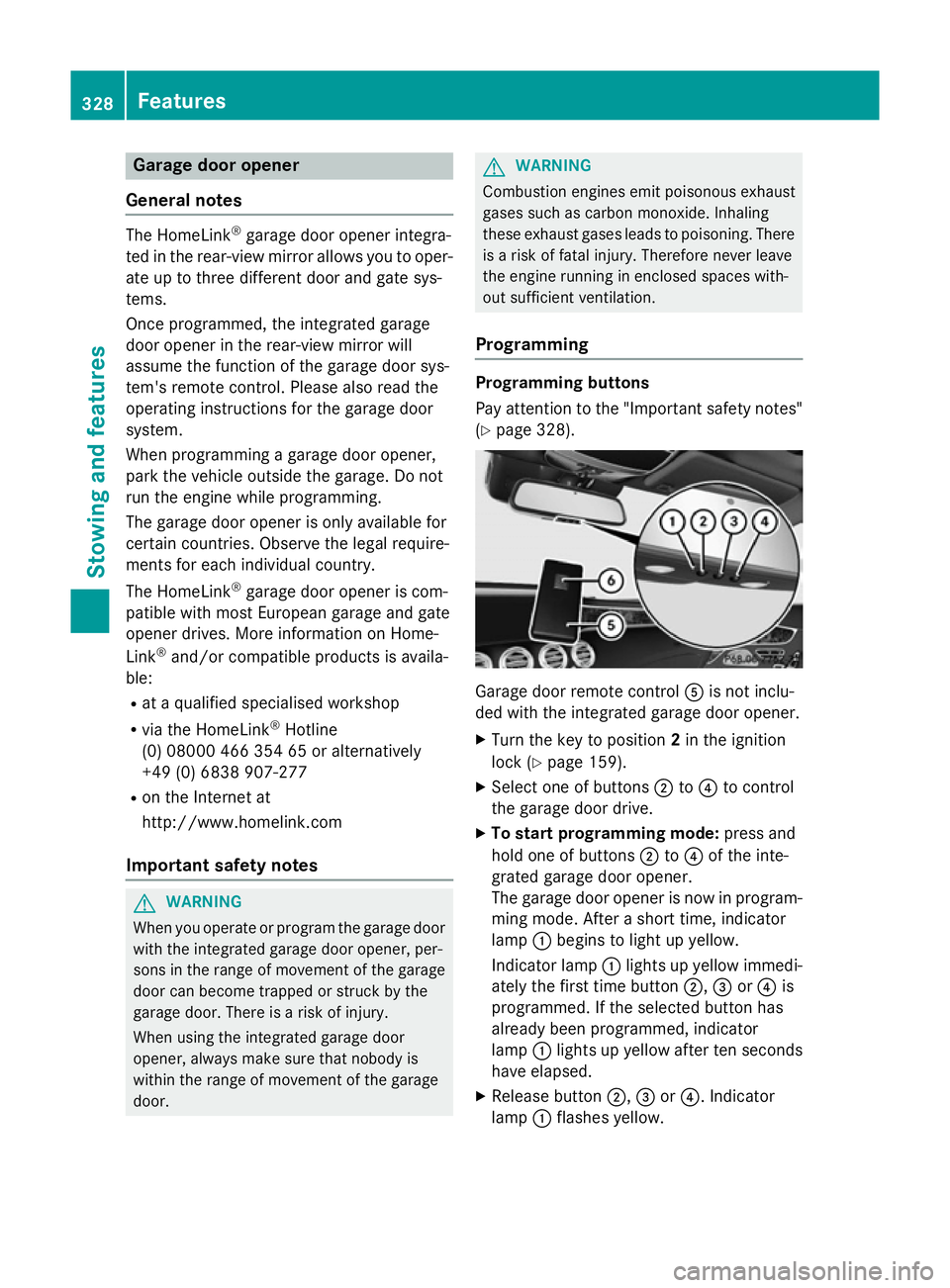
(Y page 328). Garage door remote control
Ais not inclu-
ded with the integrated garage door opener.
X Turn the key to position 2in the ignition
lock (Y page 159).
X Select one of buttons ;to? to control
the garage door drive.
X To start programming mode: press and
hold one of buttons ;to? of the inte-
grated garage door opener.
The garage door opener is now in program- ming mode. After a short time, indicator
lamp :begins to light up yellow.
Indicator lamp :lights up yellow immedi-
ately the first time button ;,=or? is
programmed. If the selected button has
already been programmed, indicator
lamp :lights up yellow after ten seconds
have elapsed.
X Release button ;,=or?. Indicator
lamp :flashes yellow. 328
FeaturesStowing and features
Page 332 of 413
X
To program the remote control: point
garage door remote control Atowards
buttons ;to? on the rear-view mirror at
a distance of 5 to 20 cm.
X Press and hold button Bon remote control
A until indicator lamp :lights up green.
When indicator lamp :lights up green:
programming is finished.
When indicator lamp :flashes green: pro-
gramming was successful. The next step is
to synchronise the rolling code.
X Release button Bof remote control Aof
the garage door drive.
If indicator lamp :lights up red: repeat the
programming process for the correspond-
ing button on the rear-view mirror. When
doing so, vary the distance between remote control Aand the rear-view mirror.
The required distance between remote
control Aand the integrated garage door
opener depends on the garage door drive
system. Several attempts may be required.
You should test every position for at least
25 second sbefore trying another position.
Synchronising the rolling code
Observe the "Important safety notes"
(Y page 328).
If the garage door system uses a rolling code,
you will also have to synchronise the garage
door system with the integrated garage door
opener in the rear-view mirror. To do this you
will need to use the programming button on
the door drive control panel. The program-
ming button may be placed at different loca-
tions depending on the manufacturer. It is
usually located on the door drive unit on the
garage ceiling.
Familiarise yourself with the garage door
drive operating instructions, e.g. under "Pro-
gramming of additional remote controls",
before carrying out the following steps.
Your vehicle must be within range of the
garage door or gate opener drive. Make sure
that neither your vehicle nor any persons/ objects are present within the sweep of the
door or gate.
X Turn the key to position 2in the ignition
lock (Y page 159).
X Get out of the vehicle.
X Press the programming button on the door
drive unit.
Usually, you now have 30 seconds to ini-
tiate the next step.
X Get into the vehicle.
X Press previously programmed button ;,
= or? of the integrated garage door
opener until the door closes.
The rolling code synchronisation is then
complete.
Problems when programming
If you have problems when programming the
integrated garage door opener, please note
the following: R Check the transmitter frequency used by
garage door drive remote control Aand
whether it is supported. The transmitter
frequency can usually be found on the back
of the garage door drive remote control.
R Replace the batteries in garage door
remote control A. This increases the like-
lihood that garage door remote control A
will transmit a strong and precise signal to the integrated garage door opener in the
rear-view mirror.
R When programming, hold remote control
A at varying distances and angles from the
button which you are programming. Try var- ious angles at a distance between 5and
30 cm or at the same angle but at varying
distances.
R If there is another remote control for the
same garage door drive, perform the pro-
gramming steps again using this remote
control. Before performing these steps,
make sure that new batteries have been
fitted in garage door drive remote control
A. Features
329Stowing and features Z
Page 333 of 413
R
Note that some remote controls transmit
only for a limited period (the indicator lamp
on the remote control goes out). Press but-ton Bon remote control Aagain before
transmission ends.
R Align the aerial cable of the garage door
opener unit. This can improve signal recep-
tion/transmission.
Opening or closing the garage door Once programmed, the integrated garage
door opener will assume the function of the
garage door system's remote control. Please
also read the operating instructions for the
garage door system.
X Turn the key to position 2in the ignition
lock (Y page 159).
X Press button ;,=or? which you have
programmed to operate the garage door.
Garage door system with a fixed code: indi-
cator lamp :lights up green.
Garage door system with a rolling code:
indicator lamp :flashes green.
The transmitter will transmit a signal for as
long as the button is pressed. The transmis-
sion is halted after a maximum of ten seconds and indicator lamp :lights up yellow. Press
button ;,=or? again if necessary.
Clearing the memory Make sure that you clear the memory of the
integrated garage door opener before selling
the vehicle.
X Turn the key to position 2in the ignition
lock (Y page 159).
X Press and hold buttons ;and ?.
The indicator lamp initially lights up yellow
and then green.
X Release buttons ;and ?.
The memory of the integrated garage door
opener in the rear-view mirror is cleared. Frequencies Europe
Country Radio type approval num-
ber
Frequency range (MHz)
AD (Andorra) 20 July 2005
MHz: 27, 30, 40, 433, 868
AT (Austria) Article 6 of Directive
1999/5/EC R&TTE 18 May
05
MHz: 27, 40, 433, 868
BE (Belgium) Article 6 of Directive
1999/5/EC R&TTE 18 May
05
MHz: 27, 40, 433, 868
BG (Bulga-
ria) Article 6 of Directive
1999/5/EC R&TTE 12 April
07
MHz: 27, 40, 433, 868 CH (Switzer-
land) Article 6 of Directive
1999/5/EC R&TTE 14357
27 May 05
MHz: 27, 40, 433, 868
CY (Cyprus) Article 6 of Directive
1999/5/EC R&TTE 5 May
05
MHz: 27, 40, 433, 868
CZ (Czech
Republic) General Licence GL-30/R/
2000 Reg No. 844 13 May
05
MHz: 27, 40, 433
DK (Den-
mark) Article 6 of Directive
1999/5/EC R&TTE 20 April
05
MHz: 27, 40, 433, 868 DE (Ger-
many) Article 6 of Directive
1999/5/EC R&TTE
7519301 29 April 05
MHz: 27, 40, 433, 868330
FeaturesStowing and features
Page 339 of 413
Useful information
i This Owner's Manual describes all mod-
els, series and optional equipment for your
vehicle that were available at the time of
going to press. National variations are pos- sible. Note that your vehicle may not be
equipped with all of the functions descri-
bed. This is also the case for systems and
functions relevant to safety.
i Read the information on qualified special-
ist workshops: (Y page 25). Engine compartment
Bonnet
Important safety notes G
WARNING
An unlocked bonnet may open while driving
and block your view. There is a risk of an acci- dent.
Never unlock the bonnet while driving. G
WARNING
When being opened and closed, the bonnet
may suddenly fall into the closed position.
There is a risk of injury to persons in the range of movement of the bonnet.
Open and close the bonnet only when nobody
is in the range of movement. G
WARNING
If you open the bonnet while the engine is
overheating or while there is a fire in the
engine compartment, you could come into
contact with hot gases or other leaking ser-
vice products. There is a danger of injury.
Allow an overheating engine to cool down
before opening the bonnet. If there is a fire in the engine compartment, leave the bonnet
closed and notify the fire brigade. G
WARNING
There are moving components in the engine
compartment. Certain components may con-
tinue to move or suddenly move again even
after the ignition has been switched off, e.g.
the radiator fan. There is a risk of injury.
If you have to carry out work in the engine
compartment:
R switch off the ignition
R never touch the dangerous areas surround-
ing moving components, e.g. the rotation
area of the fan
R remove jewellery and watches
R keep items of clothing and hair, for exam-
ple, away from moving parts. G
WARNING
The ignition system and the fuel injection sys- tem operate with a high voltage. If you touch
the live components, you could receive an
electric shock. There is a danger of injury.
Never touch components of the ignition sys-
tem or the fuel injection system when the
ignition is switched on.
Active bonnet (pedestrian protection) Operating principle
! A triggered active bonnet must be
repaired at a qualified specialist workshop
after it has been reset. The active bonnet
function will then be available again. The
additional pedestrian protection provided
by the active bonnet will then be restored.
The active bonnet is only available in certain
countries.
The active bonnet can reduce the risk of injury to pedestrians in certain accident situations.
Raising the active bonnet increases the clear- ance to hard components, such as the engine.
If the active bonnet has been triggered, it is
raised at the rear in the area around the hinge
by approximately 85 mm.
For the drive to the workshop, reset the trig-
gered active bonnet yourself. If the active 336
Engine compartmentMaintenance and care
Page 340 of 413
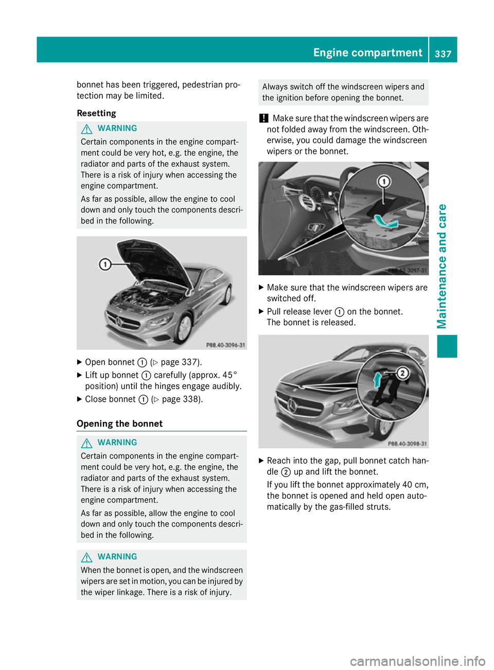
bonnet has been triggered, pedestrian pro-
tection may be limited.
Resetting G
WARNING
Certain components in the engine compart-
ment could be very hot, e.g. the engine, the
radiator and parts of the exhaust system.
There is a risk of injury when accessing the
engine compartment.
As far as possible, allow the engine to cool
down and only touch the components descri- bed in the following. X
Open bonnet :(Ypage 337).
X Lift up bonnet :carefully (approx. 45°
position) until the hinges engage audibly.
X Close bonnet :(Ypage 338).
Opening the bonnet G
WARNING
Certain components in the engine compart-
ment could be very hot, e.g. the engine, the
radiator and parts of the exhaust system.
There is a risk of injury when accessing the
engine compartment.
As far as possible, allow the engine to cool
down and only touch the components descri- bed in the following. G
WARNING
When the bonnet is open, and the windscreen wipers are set in motion, you can be injured by
the wiper linkage. There is a risk of injury. Always switch off the windscreen wipers and
the ignition before opening the bonnet.
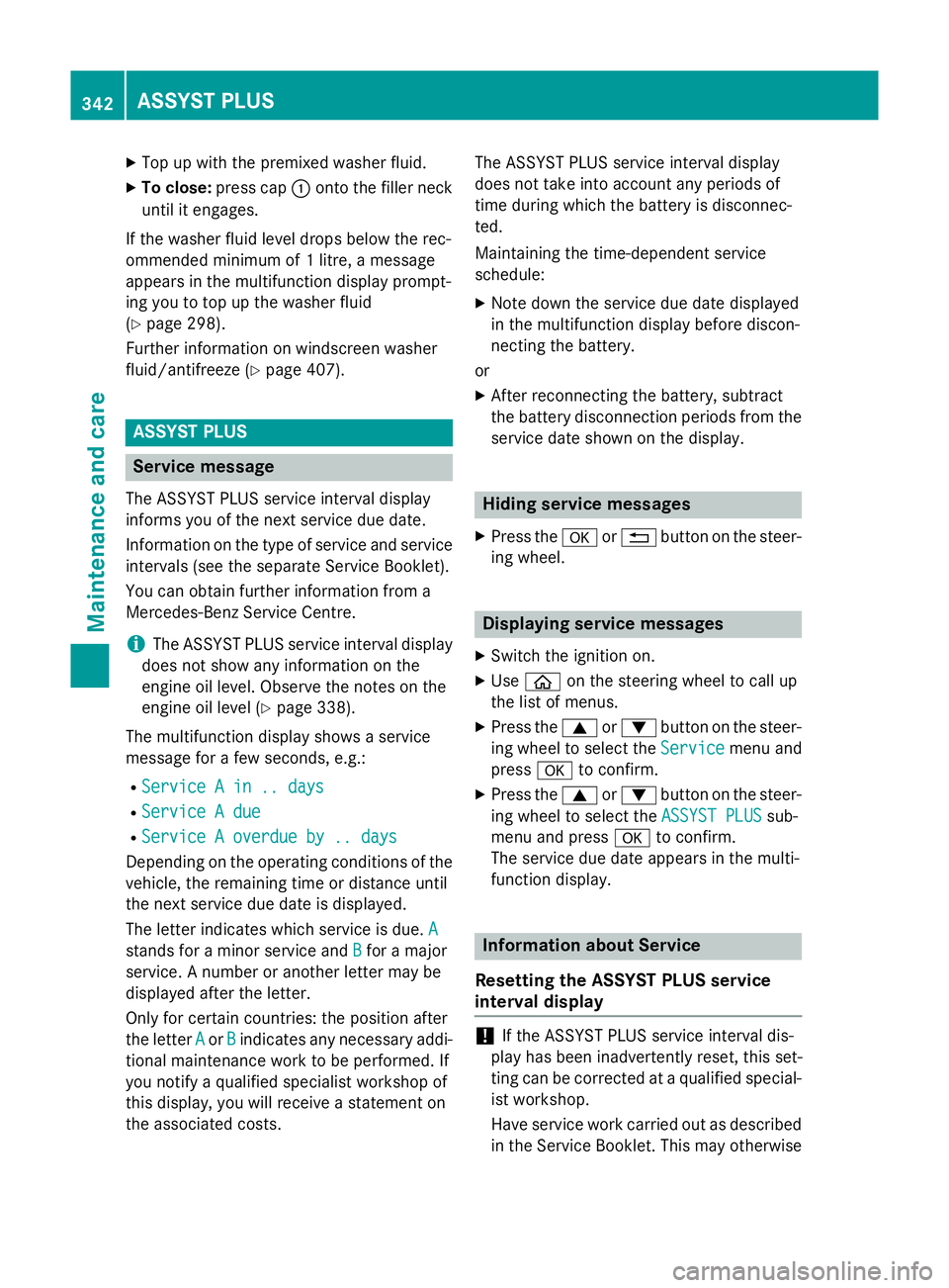
! Make sure that the windscreen wipers are
not folded away from the windscreen. Oth-
erwise, you could damage the windscreen
wipers or the bonnet. X
Make sure that the windscreen wipers are
switched off.
X Pull release lever :on the bonnet.
The bonnet is released. X
Reach into the gap, pull bonnet catch han-
dle ;up and lift the bonnet.
If you lift the bonnet approximately 40 cm, the bonnet is opened and held open auto-
matically by the gas-filled struts. Engine compartment
337Maintenance and care Z
Page 342 of 413
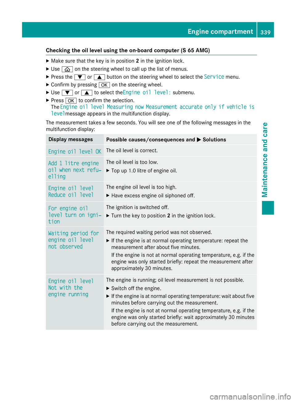
Checking the oil level using the on-board computer (S 65 AMG)
X
Make sure that the key is in position 2in the ignition lock.
X Use ò on the steering wheel to call up the list of menus.
X Press the :or9 button on the steering wheel to select the Service
Service menu.
X Confirm by pressing aon the steering wheel.
X Use : or9 to select theEngine oil level: Engine oil level: submenu.
X Press ato confirm the selection.
The Engine
Engine oil
oillevel
level Measuring
Measuring now
nowMeasurement
Measurement accurate
accurateonly
onlyif
ifvehicle
vehicle is
is
level
levelmessage appears in the multifunction display.
The measurement takes a few seconds. You will see one of the following messages in the
multifunction display: Display messages
Possible causes/consequences and
M
MSolutions Engine
Engine
oil
oillevel
level OK
OK The oil level is correct.
Add
Add
1
1litre
litre engine
engine
oil
oil when
when next
next refu‐
refu‐
elling
elling The oil level is too low.
X Top up 1.0 litre of engine oil. Engine oil level
Engine oil level
Reduce oil level Reduce oil level The engine oil level is too high.
X Have excess engine oil siphoned off. For engine oil
For engine oil
level level
turn
turnon
onigni‐
igni‐
tion
tion The ignition is switched off.
X Turn the key to position 2in the ignition lock. Waiting
Waiting
period
periodfor
for
engine oil level
engine oil level
not observed not observed The required waiting period was not observed.
X If the engine is at normal operating temperature: repeat the
measurement after about five minutes.
If the engine is not at normal operating temperature, e.g. if the
engine was only started briefly: repeat the measurement after
approximately 30 minutes. Engine oil level Engine oil level
Not with the Not with the
engine running engine running The engine is running; oil level measurement is not possible.
X Switch off the engine.
X If the engine is at normal operating temperature: wait about five
minutes before carrying out the measurement.
If the engine is not at normal operating temperature, e.g. if theengine was only started briefly: wait approximately 30 minutes before carrying out the measurement. Engine compartment
339Maintenance and care Z
Page 344 of 413
be scalded by hot coolant spraying out when
opening the cap. There is a danger of injury.
Allow the engine to cool before opening the
cap. Wear gloves and protective eyewear
when opening. Slowly turn the cap half a turn to allow pressure to escape. X
Park the vehicle on a level surface.
Only check the coolant level if the vehicle is on a level surface and the engine has
cooled down.
X Turn the key to position 2in the ignition
lock (Y page 159).
or
X Press the Start/Stop button twice
(Y page 159).
X Check the coolant temperature display in
the instrument cluster.
The coolant temperature must be below
70 †.
X Turn the key to position 0in the ignition
lock (Y page 159).
or
X Remove the Start/Stop button from the
ignition lock (Y page 159).
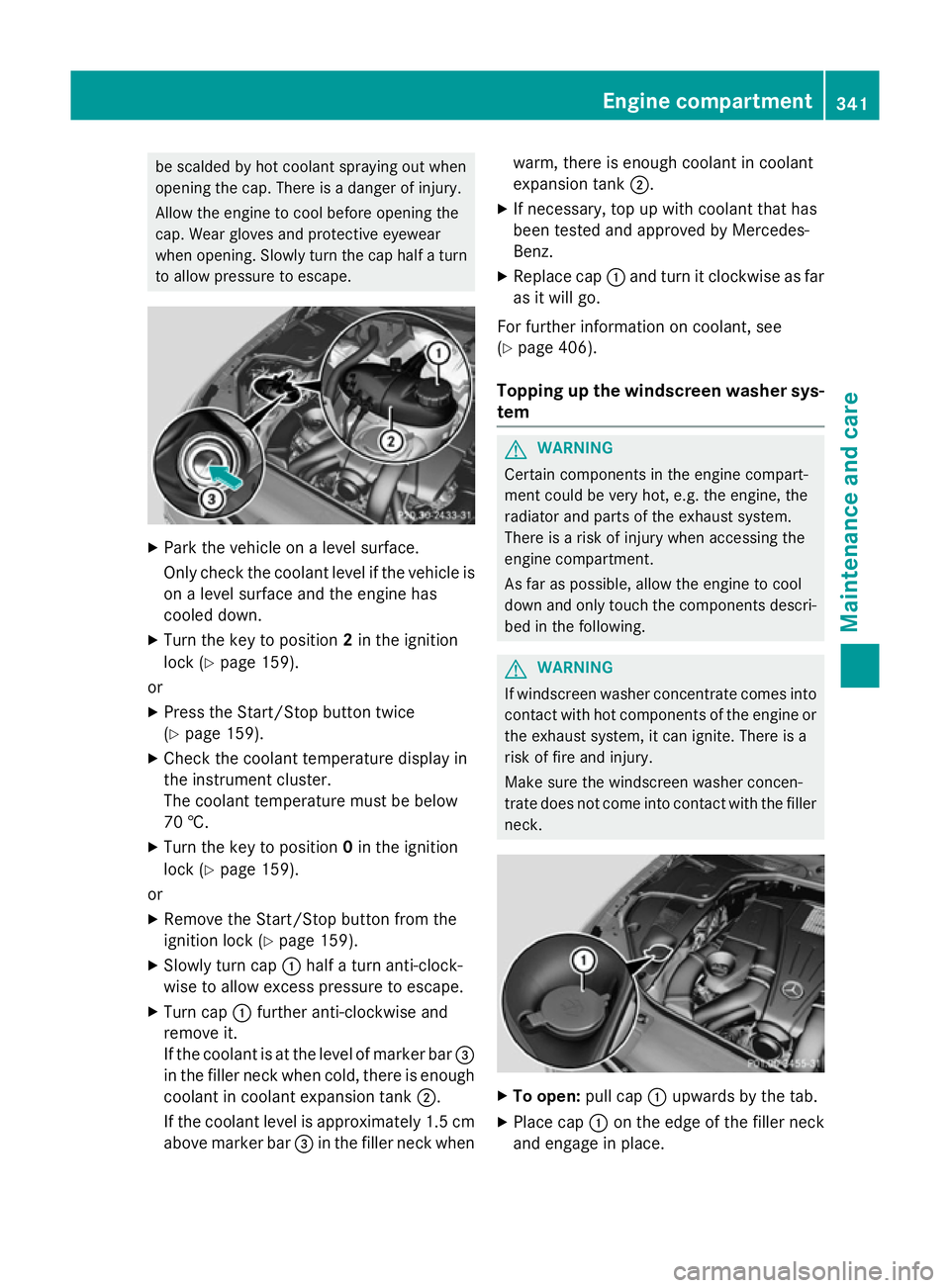
X Slowly turn cap :half a turn anti-clock-
wise to allow excess pressure to escape.
X Turn cap :further anti-clockwise and
remove it.
If the coolant is at the level of marker bar =
in the filler neck when cold, there is enough coolant in coolant expansion tank ;.
If the coolant level is approximately 1.5 cm above marker bar =in the filler neck when warm, there is enough coolant in coolant
expansion tank ;.
X If necessary, top up with coolant that has
been tested and approved by Mercedes-
Benz.
X Replace cap :and turn it clockwise as far
as it will go.
For further information on coolant, see
(Y page 406).
Topping up the windscreen washer sys-
tem G
WARNING
Certain components in the engine compart-
ment could be very hot, e.g. the engine, the
radiator and parts of the exhaust system.
There is a risk of injury when accessing the
engine compartment.
As far as possible, allow the engine to cool
down and only touch the components descri- bed in the following. G
WARNING
If windscreen washer concentrate comes into contact with hot components of the engine or
the exhaust system, it can ignite. There is a
risk of fire and injury.
Make sure the windscreen washer concen-
trate does not come into contact with the filler neck. X
To open: pull cap:upwards by the tab.
X Place cap :on the edge of the filler neck
and engage in place. Engine compartment
341Maintenance and care Z
Page 345 of 413
X
Top up with the premixed washer fluid.
X To close: press cap :onto the filler neck
until it engages.
If the washer fluid level drops below the rec-
ommended minimum of 1 litre, a message
appears in the multifunction display prompt-
ing you to top up the washer fluid
(Y page 298).
Further information on windscreen washer
fluid/antifreeze (Y page 407).ASSYST PLUS
Service message
The ASSYST PLUS service interval display
informs you of the next service due date.
Information on the type of service and service
intervals (see the separate Service Booklet).
You can obtain further information from a
Mercedes-Benz Service Centre.
i The ASSYST PLUS service interval display
does not show any information on the
engine oil level. Observe the notes on the
engine oil level (Y page 338).
The multifunction display shows a service
message for a few seconds, e.g.:
R Service A in .. days
Service A in .. days
R Service A due Service A due
R Service A overdue by .. days
Service A overdue by .. days
Depending on the operating conditions of the vehicle, the remaining time or distance until
the next service due date is displayed.
The letter indicates which service is due. A
A
stands for a minor service and B
B for a major
service. A number or another letter may be
displayed after the letter.
Only for certain countries: the position after
the letter A
A or B Bindicates any necessary addi-
tional maintenance work to be performed. If
you notify a qualified specialist workshop of
this display, you will receive a statement on
the associated costs. The ASSYST PLUS service interval display
does not take into account any periods of
time during which the battery is disconnec-
ted.
Maintaining the time-dependent service
schedule:
X Note down the service due date displayed
in the multifunction display before discon-
necting the battery.
or X After reconnecting the battery, subtract
the battery disconnection periods from the
service date shown on the display. Hiding service messages
X Press the aor% button on the steer-
ing wheel. Displaying service messages
X Switch the ignition on.
X Use ò on the steering wheel to call up
the list of menus.
X Press the 9or: button on the steer-
ing wheel to select the Service Servicemenu and
press ato confirm.
X Press the 9or: button on the steer-
ing wheel to select the ASSYST PLUS
ASSYST PLUSsub-
menu and press ato confirm.
The service due date appears in the multi-
function display. Information about Service
Resetting the ASSYST PLUS service
interval display !
If the ASSYST PLUS service interval dis-
play has been inadvertently reset, this set-
ting can be corrected at a qualified special-
ist workshop.
Have service work carried out as described in the Service Booklet. This may otherwise 342
ASSYST PLUSMaintenance and care