2014 MERCEDES-BENZ B-CLASS SPORTS ESP
[x] Cancel search: ESPPage 257 of 360
X
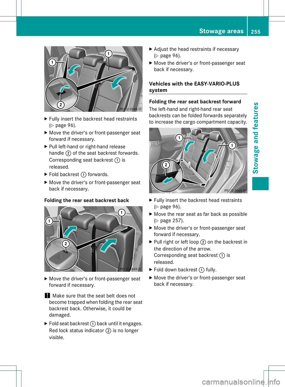
Fully insert the backrest hea drestraints
(Y page 96).
X Move the driver' sorfront-passenger seat
forward if necessary.
X Pull left-hand or right-hand release
handle 0010of the sea tbackres tforwards.
Corresponding seat backrest 001Ais
released.
X Fold backrest 001Aforwards.
X Move the driver's or front-passenger seat
back if necessary.
Folding the rear seat backrest back X
Move the driver's or front-passenger seat
forward if necessary.
! Make sure that the seat belt does not
become trapped when folding the rear seat
backrest back. Otherwise, it could be
damaged.
X Fold seat backrest 001Aback until it engages.
Red lock status indicator 0010is no longer
visible. X
Adjust the head restraints if necessary
(Y page 96).
X Move the driver's or front-passenger seat
back if necessary.
Vehicles with the EASY-VARIO-PLUS
system Folding the rear seat backrest forward
The left-hand and right-hand rear seat
backrest
scan be folded forwards separately
to increase the cargo compartment capacity. X
Fully insert the backrest head restraints
(Y page 96).
X Move the rear seat as far back as possible
(Y page 257).
X Move the driver's or front-passenger seat
forward if necessary.
X Pull right or left loop 0010on the backrest in
the direction of the arrow.
Corresponding seat backrest 001Ais
released.
X Fold down backrest 001Afully.
X Move the driver's or front-passenger seat
back if necessary. Stowage areas
255Stowage and features Z
Page 258 of 360
Folding th
erears eat backres tback X
Mov ethe driver' sorfront-pa ssenger seat
forward if necessary.
! Mak esure that th eseat belt does not
become trapped when foldin gthe rear seat
backres tback .Otherwise, it could be
damaged.
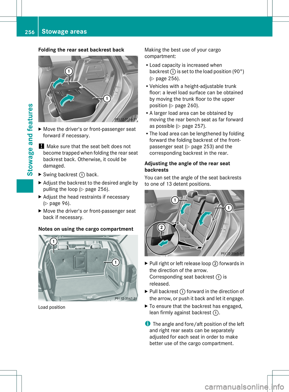
X Swing backrest 001Aback.
X Adjust the backrest to the desired angle by
pulling the loop (Y page 256).
X Adjust the head restraints if necessary
(Y page 96).
X Move the driver's or front-passenge rseat
back if necessary.
Notes on using the cargo compartment Load position Making the best use of your cargo
compartment:
R
Load capacity is increased when
backrest 001Ais set to the load position (90°)
(Y page 256).
R Vehicles with aheight-adjustable trunk
floor: alevel load surface can be obtained
by movin gthe trun kfloor to the upper
position (Y page 260).
R Al arge rload area can be obtained by
moving the rear bench seat as far forward
as possible (Y page 257).
R The load area can be lengthened by folding
forward the folding backrest of the front-
passenger seat (Y page 253) and the
corresponding backrest in the rear.
Adjusting the angle of the rear seat
backrests
You can set the angle of the seat backrests
to one of 13 detent positions. X
Pull right or left release loop 0010forwards in
the direction of the arrow.
Corresponding seat backrest 001Ais
released.
X Pull backrest 001Aforward in the direction of
the arrow, or push it back and let it engage.
X To ensure that the backrest has engaged,
lean firmly against backrest 001A.
i The angle and fore/aft position of the left
and right rear seats can be separately
adjusted for each seat in order to make
better use of the cargo compartment. 256
Stowage areasStowage and features
Page 259 of 360
Depending on the angle of the backrest,
therefore ,the righ tand left rea rseats can
be pushed back varying distances until the
backrest is resting against the cargo
compartment cover.
If the backrest comes intoc ontact with
surroundin gparts of the cargo
compartment paneling, reduce the angle of
the backrest.
Adjusting the seat fore-and-aft position
! When movin gthe rear seats back, make
sure ther eare no objects in the footwell or
behind the seats. The rear seats and/or the
objects could otherwise be damaged. X
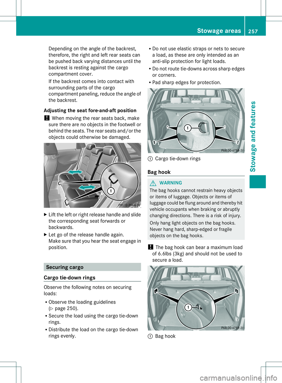
Lift the left or right release handle and slide
the correspondin gseat forwards or
backwards.
X Let go of the release handle again.
Make sure that you hear the seat engage in
position. Securing cargo
Cargo tie-down rings Observe the following notes on securing
loads:
R Observe the loading guidelines
(Y page 250).
R Secure the load using the cargo tie-down
rings.
R Distribute the load on the cargo tie-down
rings evenly. R
Do not use elastic straps or netstos ecure
al oad, as these are only intended as an
anti-slip protection for light loads.
R Do not route tie-downs across sharp edges
or corners.
R Pad sharp edges for protection. 001A
Cargo tie-down rings
Bag hook G
WARNING
The bag hooks cannot restrain heavy objects
or items of luggage. Objects or items of
luggage could be flung around and thereby hit
vehicle occupants when brakin gorabruptly
changin gdirections. There is arisk of injury.
Only hang light objects on the bag hooks.
Never hang hard, sharp-edged or fragile
objects on the bag hooks.
! The bag hook can bear amaximum load
of 6.6lbs (3kg) and should not be used to
secure aload. 001A
Bag hook Stowage areas
257Stowage and features Z
Page 261 of 360
Cargo net
Important safety notes G
WARNING
On its own ,the cargo ne tcanno tsecure or
restrain heav yobjects, items of luggag eand
heav yloads .You could be hit by an unsecured
load during sudden changes in direction,
braking or in the event of an accident .There
is an increased risk of injury or even fatal
injury.
Always store object ssothat they cannot be
flung around. Secure objects, luggage or
loads against slipping or tipping over, e.g. by
using tie downs, even if you are using the
cargo net.
It is important to use acargo net if you load
the vehicle with small object sabove the seat
backrests. For safety reasons, always use a
cargo net when transporting loads.
The cargo net is located in the stowage space
under the cargo compartment floor
(Y page 259).
X Open both Velcro fastener sand remove the
cargo net.
X Unroll and unfol dthe cargo net.
The joints on the uppe rand lowe rguide rod
should engage audibly.
The corresponding cargo ti edown rings for
tightening th ecargo ne tare in th ecargo
compartmen t(Ypage 257).
Attaching and tightening th ecargo net X
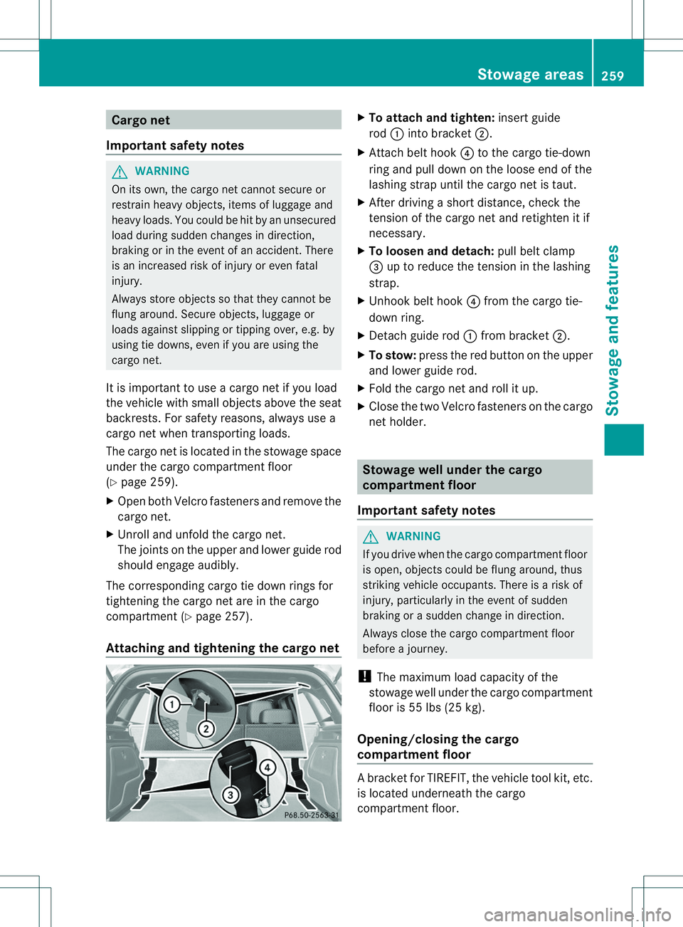
To attach and tighten: insert guide
rod 001Aintob racket 0010.
X Attac hbelt hook 0021to th ecargo tie-down
rin ga nd pull down on th eloose end of the
lashing strap until the cargo net is taut.
X After driving ashort distance, check the
tension of the cargo net and retighten it if
necessary.
X To loosen and detach: pull belt clamp
0023 up to reduce the tension in the lashing
strap.
X Unhook belt hook 0021from the cargo tie-
down ring.
X Detach guide rod 001Afrom bracket 0010.
X To stow: press the red button on the upper
and lower guide rod.
X Fold the cargo net and roll it up.
X Close the two Velcro fastener sonthe cargo
net holder. Stowage well under the cargo
compartment floor
Important safety notes G
WARNING
If you drive when the cargo compartment floor
is open, object scould be flung around, thus
striking vehicle occupants. There is arisk of
injury, particularly in the event of sudden
braking or asudden change in direction.
Always close the cargo compartment floor
before ajourney.
! The maximum load capacity of the
stowage well under the cargo compartment
floor is 55 lbs (25 kg).
Opening/closing the cargo
compartment floor Ab
racket for TIREFIT, the vehicl etool kit, etc.
is located underneath the cargo
compartment floor. Stowage areas
259Stowage and features Z
Page 267 of 360
X
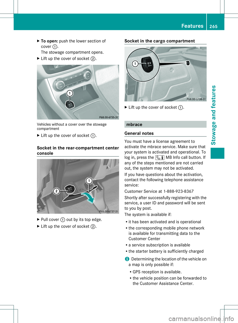
To open: push the lowe rsection of
cover 001A.
The stowage compartment opens.
X Lift up the cover of socket 0010.Vehicles without
acover over the stowage
compartment
X Lift up the cover of socket 001A.
Socket in the rear-compartment center
console X
Pull cover 001Aout by its top edge.
X Lift up the cover of socket 0010.Socket in the cargo compartment X
Lift up the cover of socket 001A. mbrace
General notes You must have
alicense agreement to
activat ethe mbrace service. Make sure that
your system is activated and operational. To
log in, press the 001FMB Infoc all button.If
any of the steps mentioned are not carried
out, the system may not be activated.
If you have questions about the activation,
contact the following telephon eassistance
service:
Customer Service at 1-888-923-8367
Shortly after successfully registering with the
service, auser ID and password will be sent
to you by post.
The system is available if:
R it has been activated and is operational
R the correspondin gmobile phone network
is available for transmitting data to the
Customer Center
R as ervic esubscription is available
R the starter batter yissufficiently charged
i Determinin gthe location of the vehicle on
am ap is only possible if:
R GPS reception is available.
R the vehicle position can be forwarded to
the Customer Assistance Center. Features
265Stowage and features Z
Page 269 of 360
An emergency cal
lcan also be initiated
manually.
As soo nasthe emergency call has been
initiated, the indicator lamp in the SOS button
flashes. The multifunction displays hows the
Connecting Call message.
The audioo utput is muted.
Once the connection has been made, the
Call Connected message appears in the
multifunction display.
All important information on the emergency
is transmitted, for example:
R Current location of the vehicle (as
determined by the GPS system)
R Vehicle identification number
R Information on the severity of the accident
Shortly after the emergency call has been
initiated, avoice connection is automatically
established between the Customer
Assistance Center and the vehicle occupants.
R If the vehicle occupants respond, the
Mercedes-Benz Customer Assistance
Center attempts to get more information
on the emergency.
R If there is no response from the vehicle
occupants, an ambulance is immediately
sent to the vehicle.
If no voice connection can be established to
the Mercedes-Benz Customer Assistance
Center, the system has been unable to initiate
an emergency call.
This can occur, for example, if the relevant
mobile phone network is not available. The
indicator lamp in the SOS button flashes
continuously.
The Call Failed message appears in the
multifunction displaya nd must be confirmed.
In this case, summon assistance by other
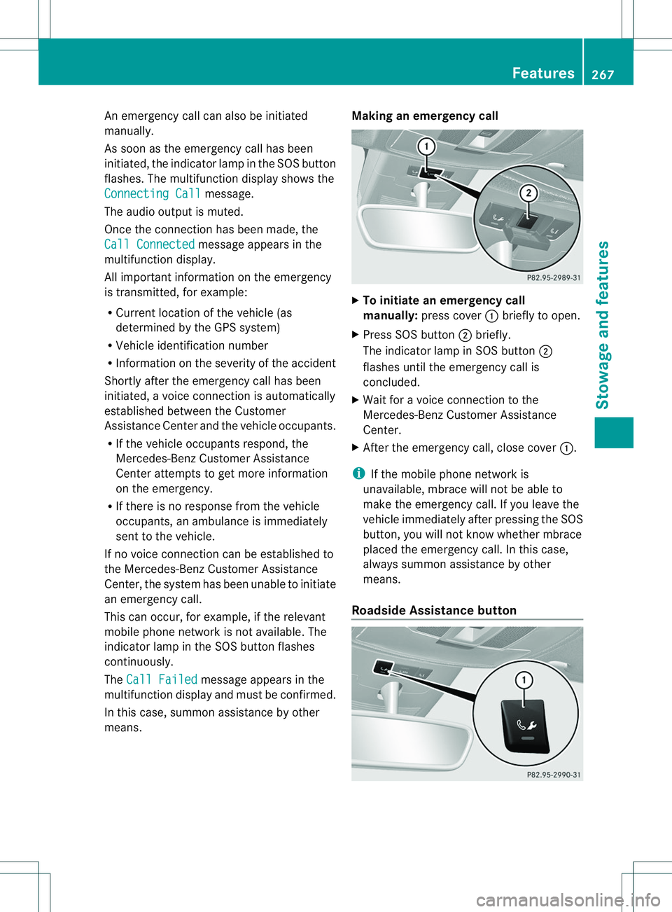
means. Making an emergency call
X
To initiate an emergency call
manually: press cover 001Abriefly to open.
X Press SOS button 0010briefly.
The indicator lamp in SOS button 0010
flashes until the emergency call is
concluded.
X Wait for avoice connection to the
Mercedes-Benz Customer Assistance
Center.
X After the emergency call, close cover 001A.
i If the mobile phone network is
unavailable, mbrace will not be able to
make the emergency call. If you leave the
vehicle immediately after pressing the SOS
button, you will not know whether mbrace
placed the emergency call. In this case,
always summon assistance by other
means.
Roadside Assistance button Features
267Stowage and features Z
Page 270 of 360
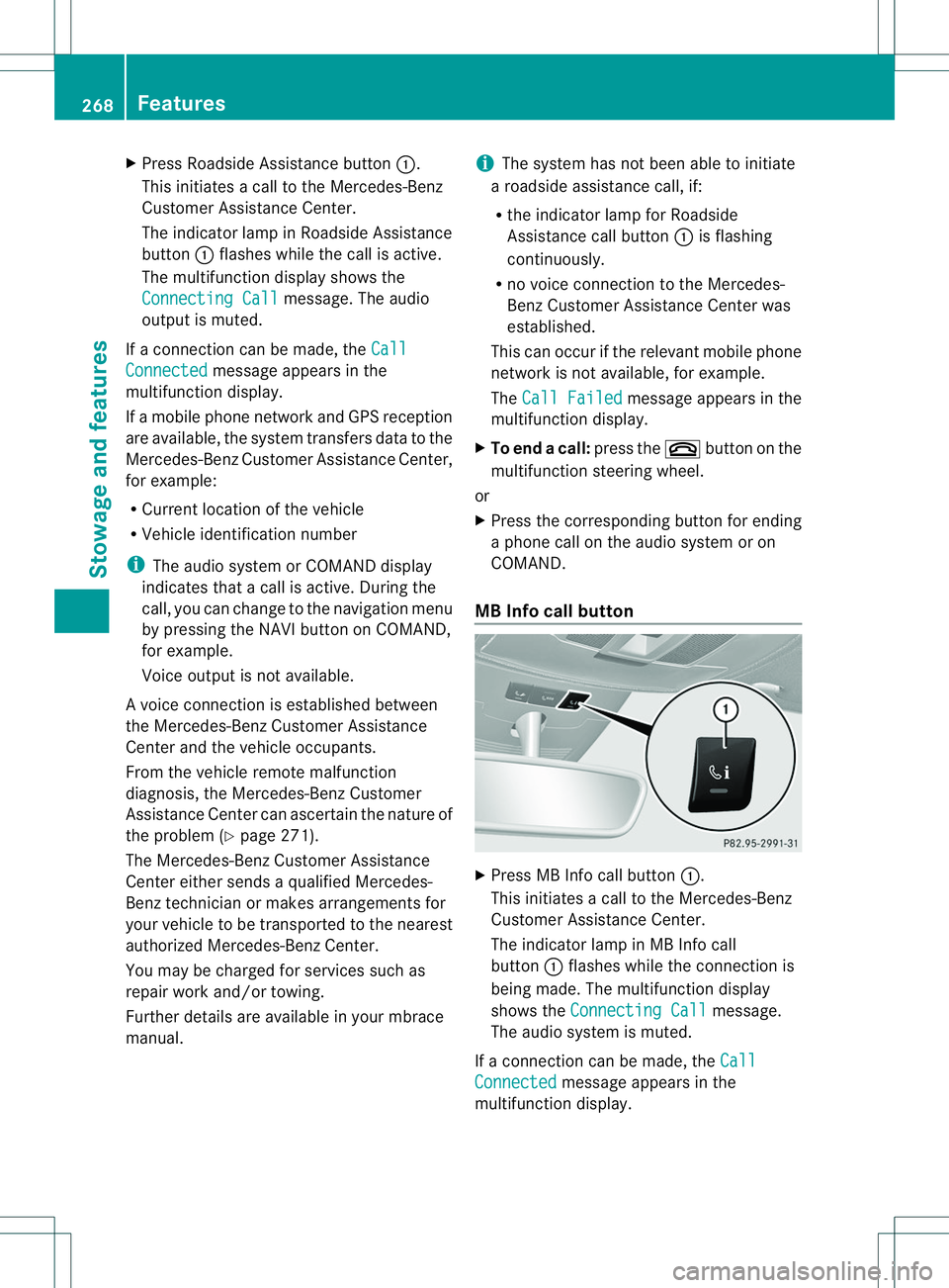
X
Press Roadside Assistance button 001A.
This initiates acall to the Mercedes-Benz
Customer Assistance Center.
The indicator lamp in Roadside Assistance
button 001Aflashes while the call is active.
The multifunction display shows the
Connectin gCall message. The audio
output is muted.
If ac onnection can be made, the CallConnected message appears in the
multifunction display.
If am obile phone network and GPS reception
are available, the system transfers data to the
Mercedes-Benz Customer Assistance Center,
for example:
R Current location of the vehicle
R Vehicle identification number
i The audio system or COMAND display
indicates that acall is active. During the
call, you can change to the navigation menu
by pressing the NAVI button on COMAND,
for example.
Voice output is not available.
Av oice connection is established between
the Mercedes-Benz Customer Assistance
Center and the vehicle occupants.
From the vehicle remote malfunction
diagnosis, the Mercedes-Benz Customer
Assistance Center can ascertain the nature of
the problem (Y page 271).
The Mercedes-Benz Customer Assistance
Center either sends aqualified Mercedes-
Benz technician or makes arrangement sfor
your vehicle to be transported to the nearest
authorized Mercedes-Benz Center.
You may be charged for services such as
repair work and/or towing.
Further details are available in your mbrace
manual. i
The system has not been able to initiate
ar oadside assistance call, if:
R the indicator lamp for Roadside
Assistance call button 001Ais flashing
continuously.
R no voice connection to the Mercedes-
Benz Customer Assistance Center was
established.
This can occur if the relevant mobile phone
network is not available, for example.
The Call Failed message appears in the
multifunction display.
X To end acall: press the 0008button on the
multifunctio nsteering wheel.
or
X Press the corresponding button for ending
ap hone cal lonthe audi osystemoron
COMAND.
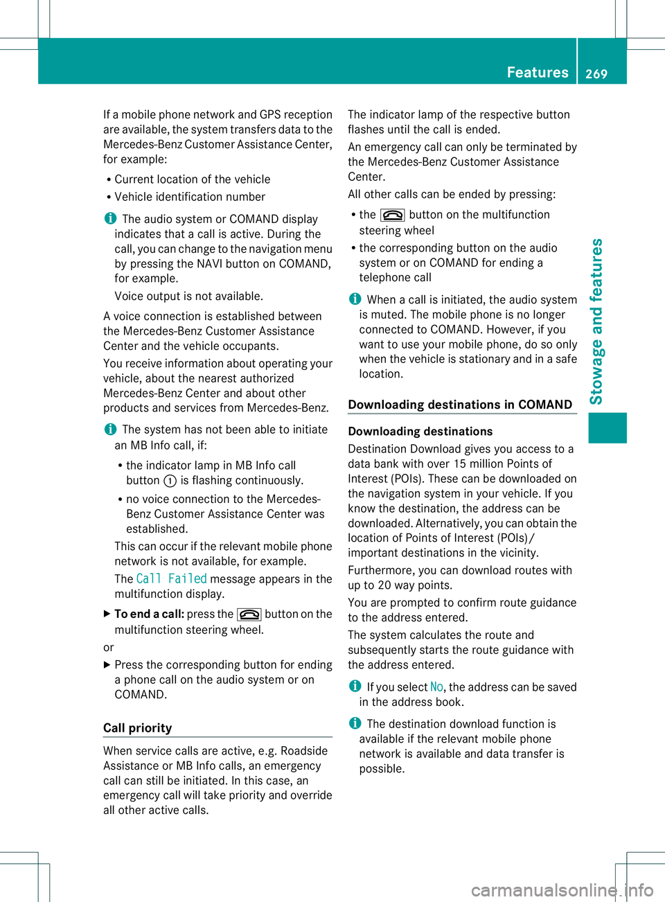
MB Info call button X
Press MB Info call button 001A.
This initiate sacall to th eMercedes-Benz
Custome rAssistance Center.
The indicator lamp in MB Info call
button 001Aflashes while the connection is
being made. The multifunction display
shows the Connecting Call message.
The audios ystem is muted.
If ac onnection can be made, the Call Connected message appears in the
multifunction display. 268
FeaturesStowage and features
Page 271 of 360
If
am obilep hone network and GPS reception
are available, the system transfers data to the
Mercedes-Benz Customer Assistance Center,
for example:
R Current location of the vehicle
R Vehicle identification number
i The audio system or COMAND display
indicates that acall is active. During the
call,y ou can change to the navigation menu
by pressing the NAVI button on COMAND,
for example.
Voice outputisn ot available.
Av oice connection is established between
the Mercedes-Benz Customer Assistance
Center and the vehicle occupants.
You receive information about operating your
vehicle, about the nearest authorized
Mercedes-Benz Center and about other
products and services from Mercedes-Benz.
i The system has not been able to initiate
an MB Info call, if:
R the indicator lamp in MB Info call
button 001Ais flashing continuously.
R no voice connection to the Mercedes-
Benz Customer Assistance Center was
established.
This can occur if the relevant mobile phone
network is not available, for example.
The Call Failed message appears in the
multifunction display.
X To end acall: press the 0008button on the
multifunctio nsteering wheel.
or
X Press the corresponding button for ending
ap hone cal lonthe audi osystemoron
COMAND.
Call priority When servic
ecallsa re active, e.g. Roadside
Assistanc eorMBInfoc alls, an emergency
call can still be initiated. In this case, an
emergenc ycall will tak epriorit yand override
all other active calls. The indicator lamp of th
erespective button
flashes until th ecall is ended.
An emergenc ycall can only be terminated by
th eM ercedes-Ben zCustome rAssistance
Center.
All other calls can be ended by pressing:
R the 0008 button on the multifunction
steering wheel
R the corresponding button on the audio
system or on COMAND for ending a
telephone call
i When acall is initiated, the audios ystem
is muted. The mobile phone is no longer
connected to COMAND. However, if you
want to use your mobile phone, do so only
when the vehicle is stationary and in asafe
location.
Downloading destinations in COMAND Downloading destinations
Destination Download gives you access to a
data bank with over 15 millionP oints of
Interest (POIs). These can be downloaded on
the navigation system in your vehicle. If you
know the destination ,the address can be
downloaded. Alternatively, you can obtain the
location of Points of Interest (POIs)/
important destination sinthe vicinity.
Furthermore, you can download routes with
up to 20 way points.
You are prompted to confirm route guidance
to the address entered.
The system calculates the route and
subsequently startst he route guidance with
the address entered.
i If you select No ,t
he address can be saved
in the address book.
i The destination download function is
available if the relevant mobile phone
network is available and data transfer is
possible. Features
269Stowage and features Z